

Powerex PX-S10, PX-S20 Owners And Installation Manual
PX-S10 / PX-S20
Owners and
Installation Manual
. Main features
1. IP68 waterproof and aluminum housing.
2. Automatic identification of 12V/24V system voltage.
3. LED digital display.
4. External temperature sensor for ambient temperature compensation.
5. Over charging protection, over discharging protection, over load, short circuit
protection, reverse polarity protection.
6.
. Installation and wiring
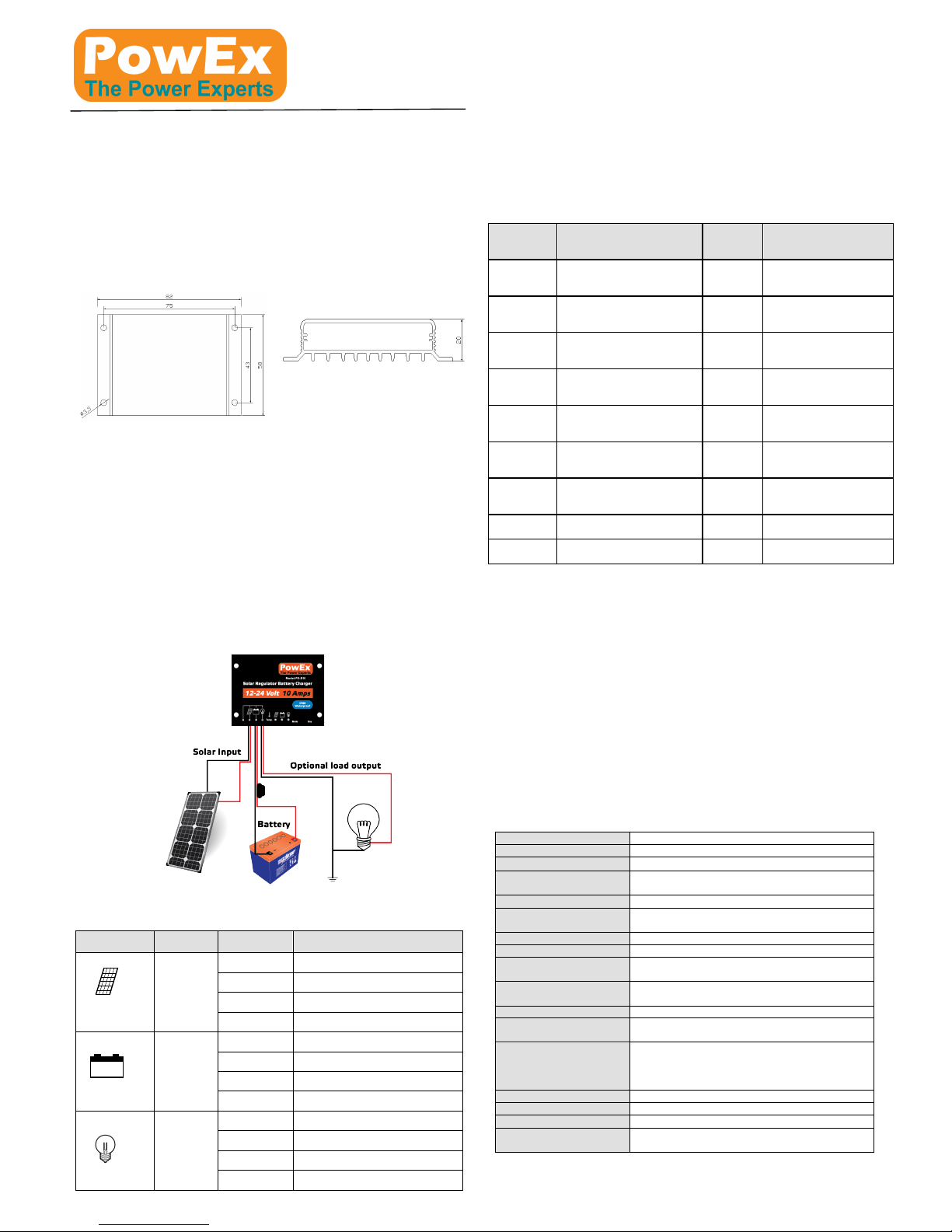
1. Installation of controller should be stable and dimensions are as follows:
Overall dimension: 82×58×20mm (PX-S10) 82×100×20mm (PX-S20)
Installation dimension: 43×75mm (PX-S10) 86×75mm (PX-S20)
Installation hole diameter: 3.5mm
2. The controller can be used for 12V or 24V battery banks. Once the battery is
connected it will automatically detect whether it’s connect to a 12V or 24V battery
bank. For 12 Volt battery banks the digital display will show “0.” when the battery is
first connected. For 24V battery banks the digital display will show “1.”. So please
check to ensure it’s detected the correct battery bank size.
3. The controller is designed to share the positive (+) pole. Please connect the
positives of storage battery, solar input and the load (if being used) to the red
(positive +) wire of the controller
4. Connect Battery Black negative (-) wire to the Battery. (Make sure it auto detects
the correct battery voltage) – We also recommend using adequate size fuse to suit
your application.
5. Connect Solar Black negative (-) wire to the Battery: We recommend using
adequate size fuse to suit your application.
6. Connecting pole ‘-’o f the load: connect the load wire to the load output end of
controller. Current should not exceed the rated current of controller. We
recommend using adequate size fuse to suit your application.
Wiring diagram is as follows: Please use adequate size wiring/ fuses.
Please install the controller in a ventilated area and close to the battery to ensure the
battery compensation is effective .
. Status indications
LED lamp
Indications
LED Status
Functions
Charging
indication
On
There is voltage on battery panel
Off
No voltage on battery panel
Slow flash
Charging
Fast flash
Over voltage on Solar input
Storage
Battery
On
Battery connected OK
Off
Battery is not connected
Slow flash
Battery is Low Voltage
Fast flash
Battery is deeply discharged
Load
On
Load is on
Off
Load is off
Slow flash
Overload protection mode
Fast flash
Short circuit protection mode
. Modes and Settings
The PX series controllers have five working modes.
1. Purely light-operated (0): When there is no sunlight, the load output will turn on.
When there is sunlight the load output will turn off.
2. Light-operated + time-controlled (1~4.): Starting process is same as above
however the load will automatically turn off after the time period selected. Set time
will be 1 to 14 hours.
3. Manual mode (5.): Under this mode, users can control the load-on and load-off by a
short press of the key/button. This mode is suitable to occasions in need of special
loads or for debugging.
4. Debug mode (6.): It is used for system debug. If there is light signal, load will be
closed. If there is no light signal, load will be opened. It is convenient for checking
the correctness of the system during installation and debugging.
5. Long-term On mode (7.): If being powered on, the load will be under the output
status all the time. This mode is suitable for loads in need of 24-hour power supply.
LED
Display
Mode
LED
Display
Mode
0
Purely light-operated
9
Light-operated +
time-controlled for 9
hours
1
Light-operated +
time-controlled for 1 hour
0﹒
Light-operated +
time-controlled for 10
hours
2
Light-operated +
time-controlled for 2 hours
1﹒
Light-operated +
time-controlled for 11
hours
3
Light-operated +
time-controlled for 3 hours
2﹒
Light-operated +
time-controlled for 12
hours
4
Light-operated +
time-controlled for 4 hours
3﹒
Light-operated +
time-controlled for 13
hour
5
Light-operated +
time-controlled for 5 hours
4﹒
Light-operated +
time-controlled for 14
hours
6
Light-operated +
time-controlled for 6 hours
5﹒
Manual mode
(Key/button turns load
on/off)
7
Light-operated +
time-controlled for 7 hours
6﹒
Debug mode
8
Light-operated +
time-controlled for 8 hours
7﹒
Long-term On mode
. How to change settings
Press the mode key/button for more than 3s until the Display starts flashing. Keep
pressing the key/button until it shows the desired mode/setting. Once you have the
correct mode/setting selected, wait for more than 3 seconds and settings will be saved.
. Safety suggestions
1. Please do not immerse the controller into corrosive liquid. Otherwise, controller
may be damaged and harmful gas may be generated.
2. When connecting 24V system, terminal voltage of battery panel may surpass the
human body safety voltage. If operations are needed, insulating tools should be
used and hands must be dry.
3. If storage battery is connected in reverse, the controller would not be damaged.
However, there may be output of negative voltage at the load end which may
damage anything connected to your load
4. Storage battery may generate combustible gas and therefore should be far away
from sparks.
5. Please make sure that children are far away from the storage battery and the
controller.
6. Please follow the safety suggestions given by the battery manufacturer.
. Instructions for parameters
System voltage
12V/24V Auto
System current
10A/20A
No-load loss
< 5mA/10A; < 8mA/20A
Solar Input Voltage
PX-S10 - 55VDC Max. 150W(12V) – 300W(24V)
PX-S20 - 55VDC Max. 300W(12V) – 600W(24V)
Overvoltage protection
17.0V / 34V
Equalising charging
voltage
14.7 / 29.4V
Boost charging voltage
14.4V / 28.8V
Float charging voltage
13.6V / 27.2V
Return voltage during
charging
13.2V / 26.4V
Return voltage for
over-discharging
12.5V / 25V
Low Voltage Disconnect
11.5V / 23V
Temperature
compensation
-4.0mv//2V;
Overload and short
circuit protection
1.25 times of rated current: 30s;
1.5 times of rated current: 5s overload protection
activity;
≥3 times of rated current: short circuit protection
Working temperature
-35DegC to +65DegC;
Protection level
IP68
Weight
140g (PX-S10) 300g (PX-S20)
Dimensions
82×58×20mm (PX-S10) 82×100×20mm
(PX-S20)
Specifications subject to change without notice : 08/15 Rev 1.1

. Wiring Diagram
1) Solar Input wires are 600mm long – (Wires are stripped)
2) Battery Output wires are 600mm long with Ring Terminal Connections.
3) Optional load Output wires are 200mm long – (Insulated)
. Example Solar Panel Only Connection Diagram
. Trouble Shooting
Phenomena
Problems and solutions
There is sunlight but indicator
lamp of battery panel is not on.
Please check the wiring of solar panel.
Indicator lamp for charging of
battery panel flashes fast.
Overvoltage on solar input
Indicator lamp for battery is
OFF.
Power supply to storage battery fails. Please
check the connection of storage battery.
Indicator lamp of storage
battery flashes fast and there is
output .
Storage battery is over discharged. Charge
the battery fully.
Indicator lamp of load flashes
slowly and there is no output.
Power of load exceeds rated power. Turn off
all loads and press and hold the key/button
until the unit resets.
Indicator lamp of load flashes
fast and there is no output.
Load is under short circuit. Turn off all loads
check and fix the short circuit. Once the
short circuit has been fixed, press and hold
the key/button until the unit resets.
Indicator lamp of load is on
permanently and there is no
output
Please check load connections and fuse.
2 YEAR PRODUCT WARRANTY
Zylux Distribution Pty. Ltd. (ABN 66 101 378 009) of 166 Christmas Street, Fairfield,
Victoria, 3078, Australia warrants to the Customer that this product is substantially free
from defects in materials and workmanship under normal use for a period of Two
Years from the Date of Purchase. Please ensure you keep a copy of your purchase
receipt on file as this will be required to validate your warranty.
Obtaining Warranty Service:
Within the warranty period, the Customer must contact the authorised supplier / retailer
where the product was purchased or alternatively you can contact the Oz Charge
service centre through one of the following methods:
Service help phone: Within Australia (03) 9482 2203
Outside of Australia: +61 3 9482 2203
If the Authorised Supplier and / or service centre concludes that while under normal
use, a product failure or malfunction occurred during the warranty period and was
caused by a defect in material or workmanship (see Exclusions), the Customer will be
asked to ship to the nearest service point for repair or replacement, at our discretion.
The product must be packaged appropriately for safe shipment. To prove that the
product is under warranty, the customer should enclose a copy of their receipt for proof
of purchase. It is recommended that returned products be sent by registered mail as
Zylux Distribution Pty. Ltd. (PowEx) accepts no responsibility / liability for goods lost or
damaged in transit.
Exclusions:
If upon receiving a product for repair and if testing and examining the product has
disclosed that the alleged defect or malfunction in the product does not exist or was
caused by the Customer or any third persons misuse, neglect, physical abuse, water
damage, unauthorised attempts to open, exposure to extremely high temperatures,
tampered with or repaired by an unauthorised persons, this will not be covered under
this warranty. Also charges may apply to any product returned which has no fault found
or if the warranty has expired or been void.
This Warranty is also void if:
1. The warranty seal is broken or altered.
2. The warranty period has expired.
3. The product has been tampered with or repaired by an unauthorised person.
Our goods come with guarantees that cannot be excluded under the Australian
Consumer Law. You are entitled to a replacement or refund for a major failure and
compensation for any other reasonably foreseeable loss or damage. You are also
entitled to have the goods repaired or replaced if the goods fail to be of acceptable
quality and the failure does not amount to a major failure. For New Zealand customers,
this warranty is in addition to statutory rights observed under New Zealand legislation.
 Loading...