

PRELIMINARY
Powerex, Inc., Hillis S treet, Youngwood, Pennsylvania 15697 (724) 925-7272
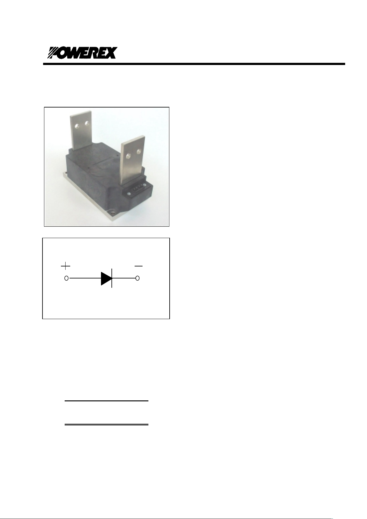
POW-R-BLOK
TM
www.pwrx.com
Single Diode Isolated Module
2500 Amperes / Up to 2400 Volts
Description:
Powerex Single Diode Modules are
designed for use in applications
requiring rectification and isolated
packaging. The modules are isolated
for easy mounting with other
components on a common heatsink.
Features:
T Electrically Isolated Heatsinking
T Compression Bonded Elements
T Metal Baseplate
T Low Thermal Impedance
for Improved Current Capability
Benefits:
T No Additional Insulation
Components Required
T Easy Installation
T No Clamping Components
Required
T Reduce Engineering Time
Applications:
T Bridge Circuits
T AC & DC Motor Drives
T Battery Supplies
T Power Supplies
T Large IGBT Circuit Front Ends
11/06/2002
PS41__25
Ordering Information
:
Select the complete eight-digit
module part number from the table
below.
Example: PS412425 is a 2400 Volt,
2500A Average Dual Diode
Isolated
POW-R-BLOK
TM
Module
Type
Voltage
Volts (x100)
Current
Amperes
(x100)
PS41
18
20
22
24
25

PRELIMINARY
Powerex, Inc., Hillis S treet, Youngwood, Pennsylvania 15697 (724) 925-7272
POW-R-BLOK
TM
Single Diode Isolated Module
2500 Amperes / Up to 2400 Volts
Absolute Maximum Ratings
Characteristics Conditions Symbol Units
Repetitive Peak Reverse Bloc king Voltage V
RRM
Up to 2400 V
Non-Repetitive Peak Block i ng V ol tage
(t < 5 msec)
V
RSM
V
RRM
+ 100V V
RMS Current Per Diode
(180
o
Conduction)
180
°°°°
Conduction, T
C
=90
°°°°
C
180° Conduction, T
C
=92°C
180° Conduction, T
C
=98°C
180° Conduction, T
C
=104°C
I
F(RMS)
I
F(RMS)
I
F(RMS)
I
F(RMS)
3925
3768
3454
3140
A
A
A
A
Average Forward Current Per Diode
(180
o
Conduction)
180
°°°°
Conduction, T
C
=90
°°°°
C
180° Conduction, T
C
=92°C
180° Conduction, T
C
=98°C
180° Conduction, T
C
=104°C
I
F(AV)
I
F(AV)
I
F(AV)
I
F(AV)
2500
2400
2200
2000
A
A
A
A
Peak One Cycle Surge Current, Non-Repetitive
Tj = 25C, Vr = 0
60 Hz
50 Hz
I
FSM
I
FSM
90,000
83,000
A
A
Peak One Cycle Surge Current, Non-Repetitive
Tj = 25C, Vr = Vrrm
60 Hz
50 Hz
I
FSM
I
FSM
61,000
55,600
A
A
Peak One Cycle Surge Current, Non-Repetitive
Tj = 125C, Vr = 0
60 Hz
50 Hz
I
FSM
I
FSM
79,600
72,600
A
A
Peak One Cycle Surge Current, Non-Repetitive
Tj = 125C, Vr = Vrrm
60 Hz
50 Hz
I
FSM
I
FSM
53,000
48,400
A
A
Peak Three Cycle Surge Current, Non-Repetit i ve 60 Hz, Tj = 125C, Vr = Vrrm I
FSM
42,000 A
Peak Ten Cycle Surge Current, Non-Repetit i ve 60 Hz, Tj = 125C, Vr = Vrrm I
FSM
33,500 A
I2t for Fusing for One Cycle
Tj = 125C, Vr = Vrrm
8.3 milliseconds
10 milliseconds
I2t
I
2
t
11.7 x 10
6
11.7 x 10
6
A
2
sec
A
2
sec
Operating Temperature TJ -40 to +150 °C
Storage Temperature T
stg
-40 to +150 °C
Max. Mounting Torque, M6 Mounting Screw 132
15
in. – Lb.
Nm
Max. Mounting Torque, M10 Terminal Screw 106
12
in. – Lb.
Nm
Module Weight, Typical 455 g
11.75 lb
V Isolation @ 25C
V
rms
3000 V
11/06/2002
PS41__25

PRELIMINARY
Powerex, Inc., Hillis S treet, Youngwood, Pennsylvania 15697 (724) 925-7272
POW-R-BLOKTM
Single Diode Isolated Module
2500 Amperes / Up to 2400 Volts
Electrical Characteristics, TJ=25
°°°°
C unless otherwise specified
Characteristics Symbol Test Conditions Min. Max.
Units
Repetitive Peak Reverse Leakage Current I
RRM
Up to 2400V, TJ=125°C 200 mA
Peak On-State Voltage VFM I
FM
=3000A, TJ=150°C 1.00 V
Threshold Voltage, Low-level
Slope Resistance, Low-level
V
(TO)1
r
T1
T
J
= 150°C, I = 15%I
T(AV)
to πI
T(AV)
0.681
0.051 V mΩ
Threshold Voltage, High-level
Slope Resistance, High-l e vel
V
(TO)2
r
T2
T
J
= 150°C, I = πI
T(AV)
to I
TSM
0.681
0.051 V mΩ
VFM Coefficients, Full Range
TJ = 150°C, I = 50A to 10kA
V
FM
= A+ B Ln I +C I + D Sqrt I
A =
B =
C =
D =
0.6245
1.68 E-02
6.74 E-05
-2.44 E-03
Typical Reverse Recovery Time
trr
T
J
= 25°C, Ifm = 3000A.
dI
r
/dt = 25 A/us, tp = 190 us
22 us
Thermal Characteristics
Characteristics Symbol
Max. Units
Thermal Resistance, Junction to Case
R
Θ
J-C
Per Module
0.024
°
C/W
Thermal Impedance Coeff i cients
Z
Θ
J-C
Z
Θ
J-C
= K1 (1-exp(-t/
t
1
))
+ K
2
(1-exp(-t/
t
2
))
+ K
3
(1-exp(-t/
t
3
))
+ K
4
(1-exp(-t/
t
4
))
K
1
= 4.05 E-04
K2 = 5.19 E-03
K3 = 1.63 E-02
K4 =2.13 E-03
t
1
= 6.24 E-03
t
2
= 2.46 E-01
t
3
= 8.20
t
4
= 35.3
Thermal Resistance, Case to Sink Lubricated
R
Θ
C-S
Per Module 0.009
°
C/W
11/06/2002
PS41__25

PRELIMINARY
Powerex, Inc., Hillis S treet, Youngwood, Pennsylvania 15697 (724) 925-7272
Single Diode Module
2500 Amperes / Up to 2400 Volts
11/06/2002
PS41__25
Typical On-State Forward Vo ltage Drop
0
0.5
1
1.5
2
2.5
3
3.5
4
100 1000 10000 100000
Instantaneous On-State Current - If - Amperes
On-State Voltage - Vf - Volts
(Tj = 150C)
Maximum Transient Thermal Impedance
0.000
0.005
0.010
0.015
0.020
0.025
0.001 0.01 0.1 1 10 100 1000
Time - t - Seconds
Thermal Impedance - Rjc - °C/W
(Junction To Case)
0
180 360
CONDUCTION ANGLE
Maximum On-State Power Dissipation
30°
90°
180°
0
500
1000
1500
2000
2500
0 500 1000 1500 2000 2500
Average On-State Current - If(av) - Amperes
Max. Power Dissipation Per Diode - Watts_
(Sinusoidal Waveform)
0
180
360
CONDUCTION ANGLE
Maximum Allowable Case Temperature
90°
30°
180°
80
90
100
110
120
130
140
150
0 500 1000 1500 2000 2500
Average On-State Current - If(av) - Amperes
Max. Case Temperature - Tcase -°C_
(Sinusoidal Waveform)
0
180
360
CONDUCTION ANGLE
Maximum On-State Power Dissipation
360°
180°
120°
60°
90°
0
500
1000
1500
2000
2500
3000
3500
4000
0 500 1000 1500 2000 2500 3000 3500 4000
Average On-State Current - If(av) - Amperes
Max. Power Dissipatio n Per Diode - Watts_
(Rectangular Waveform)
0
180
360
CONDUCTION ANGLE
Maximum Allowable Case Temperature
180°
120°
90°
60°
360°
60
70
80
90
100
110
120
130
140
150
0 500 1000 1500 2000 2500 3000 3500 4000
Average On-State Current - If(av) - Amperes
Max. Case Temperature - Tcase -°C_
(Rectangular Waveform)

PRELIMINARY
Powerex, Inc., Hillis S treet, Youngwood, Pennsylvania 15697 (724) 925-7272
Single Diode Module
2500 Amperes / Up to 2400 Volts
11/06/2002
PS41__25
 Loading...