

Powerex, Inc., 200 Hillis Street, Youngwood, Pennsylvania 15697-1800 (724) 925-7272
TENTATIVE
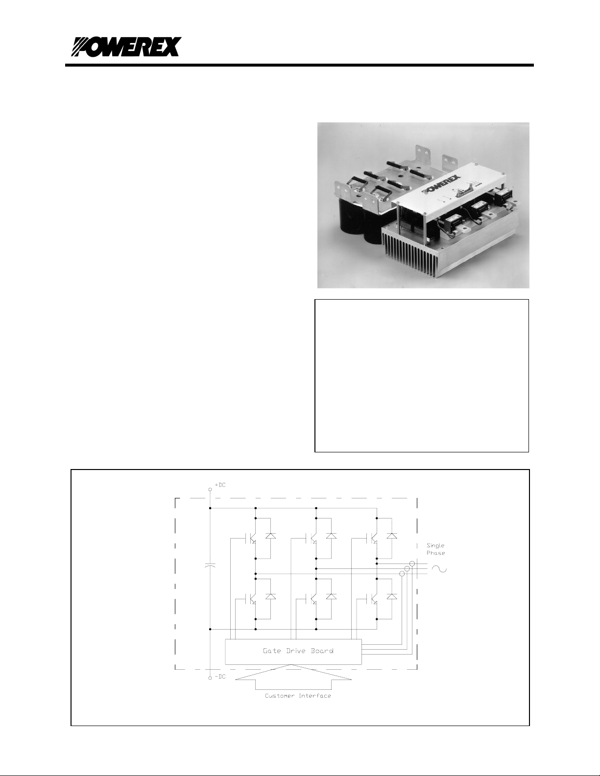
Description:
The Powerex POW-R-PAK
based power assembly that may be used as a
converter, chopper, half or full bridge, or three phase
inverter for motor control, power supply, UPS or other
power conversion applications.
The power assembly is mounted on a forced aircooled heatsink and features state-of-the-art Powerex
F-series trench gate IGBTs with low conduction and
switching losses for high efficiency operation. The
POW-R-PAK
TM
includes a low inductance laminated
bus structure, optically isolated gate drive interfaces,
isolated gate drive power supplies, and a DC-link
capacitor bank. The control board provides a
simple user interface along with built-in
protection features including overvoltage,
undervoltage lockout, overcurrent,
overtemperature, and short circuit detection.
Depending on application characteristics the
POW-R-PAK
TM
is suitable for operation with DC
bus voltages up to 800VDC and switching
frequencies above 20kHz.
Schematic
TM
is a configurable IGBT
Features:
High performance IGBT inverter bridge
Integrated gate drive with fault monitoring
& protection
System status / troubleshooting LEDs to
verify or monitor proper operation
Isolated gate drive power supplies
Low inductance laminated bus
Output current measurement & feedback
Superior short circuit detection & shoot
through prevention
PP450D120
POW-R-PAK
450A / 1200V
Half Bridge IGBT Assembly
TM
PP450D120 (-) - 1 -

TENTATIVE
Powerex, Inc., 200 Hillis Street, Youngwood, Pennsylvania 15697-1800 (724) 925-7272
PP450D120
POW-R-PAK
TM
450A / 1200V
Half Bridge IGBT Assembly
Absolute Maximum Ratings, Tj = 25°C unless otherwise specified
General Symbol Units
IGBT Junction Temperature T
Storage Temperature T
Operating Temperature T
Voltage Applied to DC terminals V
Isolation Voltage, AC 1 minute, 60Hz sinusoidal V
IGBT Inverter
Collector Current (TC = 25°C) I
Peak Collector Current (Tj < 150°C) I
Emitter Current I
Peak Emitter Current I
Maximum Collector Dissipation (Tj < 150°C) P
Gate Drive Board
j
stg
op
CC
iso
C
CM
E
EM
c
Unregulated +24V Power Supply 30 Volts
Regulated +15V Power Supply 18 Volts
PWM Signal Input Voltage 20 Volts
Fault Output Supply Voltage 30 Volts
Fault Output Current 50 mA
-40 to +150 °C
-40 to +125 °C
-25 to +85 °C
800 Volts
2500 Volts
450 Amperes
900 Amperes
450 Amperes
900 Amperes
1560 Watts
IGBT Inverter Electrical Characteristics, Tj = 25°C unless otherwise specified
Characteristics Symbol Test Conditions Min Typ Max Units
Collector Cutoff Current I
Collector – Emitter Saturation Voltage V
Emitter – Collector Voltage V
Inductive Load Switching Times
CES
CE(sat)
EC
t
d(on)
tr - - 80 ns
t
d(off)
t
Diode Reverse Recovery Time t
rr
Diode Reverse Recovery Charge Q
DC Link Capacitance 3300 µF
VCE = V
, VGE = 0V - - 1 mA
CES
IC = 450A, Tj = 25°C - 1.8 2.4 Volts
IC = 450A, Tj = 125°C - 1.9 - Volts
IE = 450A - - 3.2 Volts
- - 150 ns
VCC = 600V
= 450A
I
C
V
= 15V
f
rr
GE
= 2.1Ω
R
G
- - 450 ns
- - 300 ns
- - 150 ns
- 6.0 - µC
PP450D120 (-) - 2 -

)
TENTATIVE
Powerex, Inc., 200 Hillis Street, Youngwood, Pennsylvania 15697-1800 (724) 925-7272
PP450D120
POW-R-PAK
TM
450A / 1200V
Half Bridge IGBT Assembly
Gate Drive Board Electrical Characteristics
Characteristics Min Typ Max Units
Unregulated +24V Power Supply 20 24 30 Volts
Regulated +15V Power Supply 14.4 15 18 Volts
PWM Input On Threshold
PWM Input Off Threshold
Output Overcurrent Trip 675 Amperes
Overtemperature Trip 96 98 100 °C
Overvoltage Trip 920 Volts
DC Link Voltage Feedback See Figure Below Volts
Heatsink Temperature Feedback See Figure Below Volts
Output Current Feedback See Figure Below Volts
12 15 Volts
0 2 Volts
1000
DC Link Voltage (Volts
DC Link Feedback
900
800
700
600
500
400
300
200
100
0
012345678910
Feedback Voltage (Volts)
Thermal and Mechanical Characteristics
Characteristics Symbol Test Conditions Min Typ Max Units
IGBT Thermal Resistance, Junction to Case R
FWD Thermal Resistance, Junction to Case R
Contact Thermal Resistance R
Heatsink Thermal Resistance R
Mounting Torque, AC terminals 75 90 in-lb
Mounting Torque, DC terminals 130 150 in-lb
Mounting Torque, Mounting plate 130 150 in-lb
Weight 21 lb
Heatsink T emperature F eedback
120
100
80
60
40
20
Heatsink Temperature (ºC)
0
012345678910
Feedback Voltage (Volts)
Q Per IGBT ½ module - 0.11 0.21 °C/W
th(j-c)
D Per FWD ½ module 0.24 °C/W
th(j-c)
th(c-f)
th(f-a)
1000 LFM airflow 0.040 °C/W
- 0.020 - °C/W
Output Current F eedback
1200
900
600
300
Output Current (Amps)
0
012345678910
Feedback Voltage (Volts)
PP450D120 (-) - 3 -

Powerex, Inc., 200 Hillis Street, Youngwood, Pennsylvania 15697-1800 (724) 925-7272
TENTATIVE
PP450D120
POW-R-PAK
TM
450A / 1200V
Half Bridge IGBT Assembly
Gate Drive Board Interface Signal Definitions
Pin Signal Name Description
1 Shield Connected to circuit ground
2 PWM - 0-15 V signal controlling the duty cycle of - IGBT
3 Phase Error1
4 PWM + 0-15 V signal controlling the duty cycle of + IGBT
5 Overtemp1
6 24 VDC input power2 20 – 30 VDC input voltage range
7 24 VDC input power2 20 – 30 VDC input voltage range
8 15 VDC input power2 14.4 – 18 VDC input voltage range
9 15 VDC input power2 14.4 – 18 VDC input voltage range
10 GND Ground reference for 15 and 24 VDC inputs
11 GND Ground reference for 15 and 24 VDC inputs
12 Heatsink Temperature Analog voltage representation of heatsink temperature
13 GND3 Ground reference for analog signals
14 I
154 GND3 Ground reference for analog signals
164 DC Link Voltage Analog voltage representation of DC link voltage
Notes:
Analog voltage representation of output current
out
1. Open collectors can be pulled up to 30 V max and sink 50mA continuous.
2. Do not connect a 15 VDC and 24 VDC source to the unit at the same time, use one or the other.
3. GND signals to be used for analog feedback signals, i.e. twisted pair with I
4. Optional outputs for DC link voltage feedback
Open collector output, external pull-up resistor required
LOW = No Error; Floating = Phase overcurrent or short circuit
Open collector output, external pull-up resistor required
LOW = No Error; Floating = heatsink overtemp
out
Gate Drive Board Interface Connector
Description Symbol Type Manufacturer
With DC Link Voltage Feedback Option
Gate Drive Board Interface Header J1 0.100” x 0.100” latching header, 16 pin 3M# 3408-6002 or equivalent
Recommended Mating Socket - 0.100” x 0.100” IDC socket, 16 pin 3M# 3452-7600 or equivalent
Recommended Strain Relief -
Without DC Link Voltage Feedback Option
Gate Drive Board Interface Header J1 0.100” x 0.100” latching header, 14 pin 3M# 3314-6002 or equivalent
Recommended Mating Socket - 0.100” x 0.100” IDC socket, 14 pin 3M# 3385-7600 or equivalent
Recommended Strain Relief -
Plastic strain relief 3M# 3448-3014 or equivalent
Plastic strain relief 3M# 3448-3014 or equivalent
PP450D120 (-) - 4 -

Powerex, Inc., 200 Hillis Street, Youngwood, Pennsylvania 15697-1800 (724) 925-7272
TENTATIVE
PP450D120
POW-R-PAK
TM
450A / 1200V
Half Bridge IGBT Assembly
Performance Curves
Effective Output Current vs. Carrier Frequency (Typical)
Condition Symbol Value Units
Ambient Temperature T
DC Bus Voltage V
Load Power Factor
IGBT Saturation Voltage V
IGBT Switching Loss E
Airflow - 1000 LFM
Switching Conditions 3 phase PWM, 60Hz sinusoidal output
140
130
120
110
100
90
80
70
60
IGBT Junction Temperature
50
40
100 150 200 250 300 350 400 450 500 550 600 650 700
I
out ARMS
A
CC
cos φ
CE(sat)
SW
Typical @ TJ = 125°C Volts
Typical @ TJ = 125°C mJ
10kHz
5kHz
1kHz
40 °C
600 Volts
0.8
PP450D120 (-) - 5 -

Powerex, Inc., 200 Hillis Street, Youngwood, Pennsylvania 15697-1800 (724) 925-7272
TENTATIVE
Mechanical Drawing
PP450D120
POW-R-PAK
450A / 1200V
Half Bridge IGBT Assembly
TM
PP450D120 (-) - 6 -
 Loading...