

PM75B5L1C060
Powerex, Inc., 173 Pavilion Lane, Youngwood, Pennsylvania 15697 (724) 925-7272
www.pwrx.com
A
D
B
C
S (19 TYP.)
F
E
G
G
G
G
1 5 9 13
B P N U V W
L L
F
F
G
G
G
G
G
LF
T
F
G
G
G
H (2 TYP.)
G
G
J
K
Q
LL
N
P
M
R
TERMINAL
CODE
F
VNCWNVN1V
NC
O
1.5k
C
V
U
V
V
V
VPC
N
O
IN
SIGND GND
IN
F
CC
V
OT
OUT
U
O
F
CC
V
OT
SIGND GND
OUT
NC NCNC NC
N
O
IN
F
CC
V
OT
SIGND GND
OUT
FO
V
V
P
VP1
O
IN
F
OT
SIGND GND
OUT
VWNB
U
UPC
FO
U
V
P
UP1
1.5k1.5k
O
IN
F
CC
V
OT
SIGND GND
OUT
PU
1 V
UPC
2 UFO
3 UP
4 VUP1
5 VVPC
6 VFO
7 VP
VP1
8 V
9 NC
10 NC
11 NC
12 NC
CC
V
13 VNC
14 VN1
15 NC
16 UN
17 VN
N
18 W
19 FO
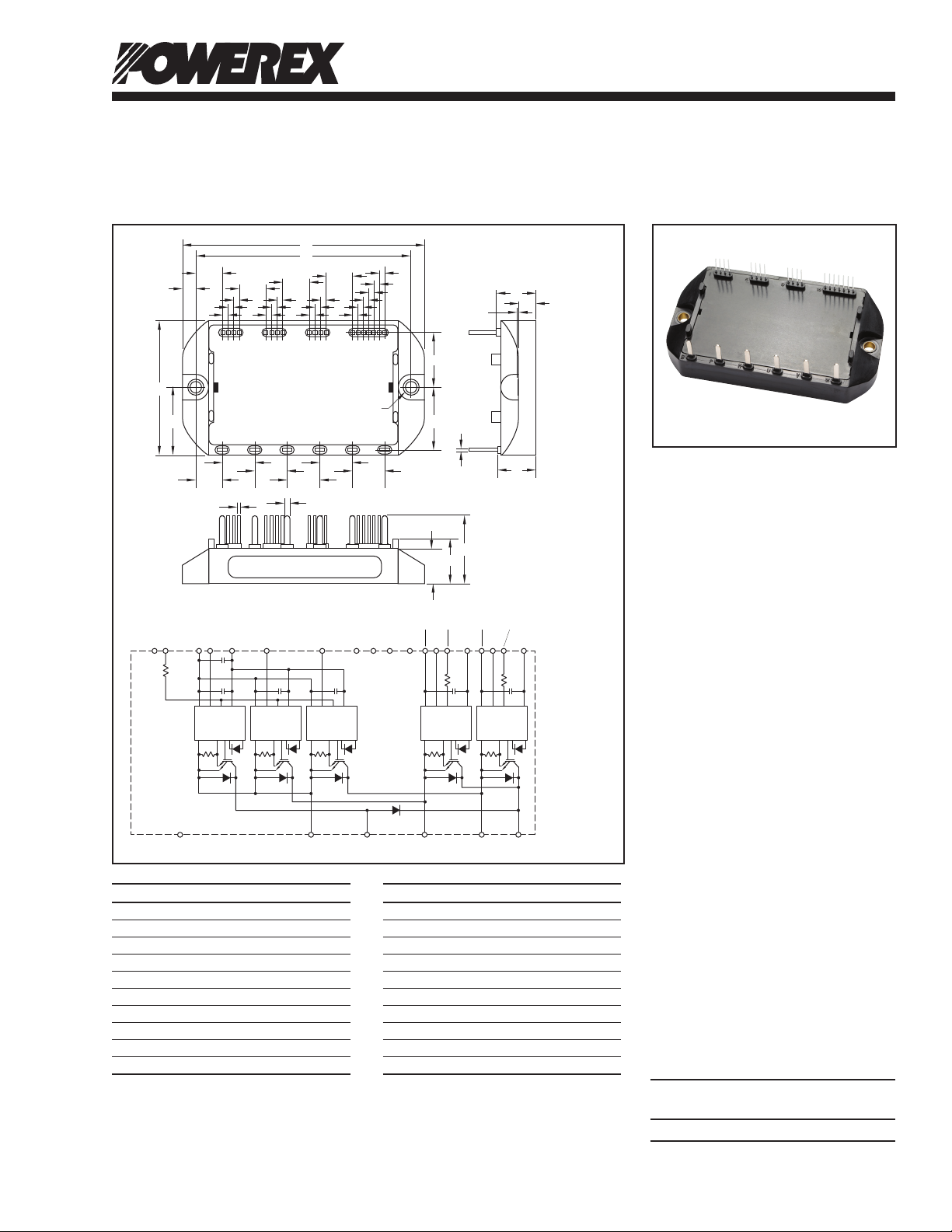
Outline Drawing and Circuit Diagram
Dim. Inches Millimeters
A 3.54 90.0
B 1.97 50.0
C 0.98 25.0
D 3.15 80.0
E 0.20 5.0
F 0.39 10.0
G 0.08 2.0
H 0.17 Dia. 4.3 Dia.
J 0.81 20.5
K 0.91 23.0
Dim. Inches Millimeters
L 0.47 12.0
M 0.012 0.3
N 0.57 14.6
P 0.26 6.7
Q 0.02 0.5
R 0.56 14.2
S 0.02 Sq. 0.5 Sq.
T 0.08 2.0
U 0.51 13.0
V 0.65 16.5
Photo Voltaic IPM
H-Bridge + 1 Chopper
75 Amperes/600 Volts
Description:
Powerex Intellimod™ Photo
Voltaic Intelligent Power Modules
are isolated base modules
designed for single phase power
switching applications. Built-in
control circuits provide optimum
gate drive and protection for the
IGBT and free-wheel diode
power devices.
Features:
£ Complete Output Power
Circuit
£ Gate Drive Circuit
£ Protection Logic
– Short Circuit
– Over Temperature
Using On-chip
Temperature Sensing
– Under Voltage
£ Low Loss Using Full Gate
CSTBT IGBT Chip
Applications:
£ PV Inverters
£ PV UPS
£ PV Power Supplies
Ordering Information:
Example: Select the complete
part number from the table below
-i.e. PM75B5L1C060 is a 600V,
75 Ampere PV-IPM.
Type Current Rating V
Amperes Volts (x 10)
PM 75 60
CES
03/11 Rev. 0
1

Powerex, Inc ., 173 Pavilion Lane, Youngwood, Pennsylvania 15697 (724) 925-7272 www.pwrx.com
PM75B5L1C060
Photo Voltaic IPM
H-Bridge + 1 Chopper
75 Amperes/600 Volts
Absolute Maximum Ratings, Tj = 25°C unless otherwise specied
Characteristics Symbol PM75B5L1C060 Units
Power Device Junction Temperature Tj -20 to 150 °C
Storage Temperature T
-40 to 125 °C
stg
Mounting Torque, M4 Mounting Screws (Typical) — 15 in-lb
Module Weight (Typical) — 135 Grams
Supply Voltage, Surge (Applied between P-N) V
Operation of Short Circuit Protections V
CC(surge)
CC(prot.)
500 Volts
450 Volts
(Applied between P-N, VD = 13.5 ~ 16.5V, Inverter Part, Tj = 125°C Start)
Isolation Voltage (60Hz, Sinusoidal, RMS, Charged Part to Base, AC 1 Minute) V
2500 Volts
ISO
Inverter Part
Collector-Emitter Voltage (VD = 15V, V
Collector Current (TC = 25°C) IC 75 Amperes
Collector Current (Pulse) I
Total Power Dissipation (TC = 25°C) P
Emitter Current (TC = 25°C, FWDi Current) IE 75 Amperes
Emitter Current (Pulse, FWDi Current) I
= 15V) V
CIN
600 Volts
CES
150 Amperes
CRM
201 Watts
tot
150 Amperes
ERM
Converter Part
Collector-Emitter Voltage (VD = 15V, V
Collector Current (TC = 25°C) IC 75 Amperes
Collector Current (Pulse) I
Total Power Dissipation (TC = 25°C) P
Emitter Current (TC = 25°C, FWDi Current) IE 75 Amperes
Emitter Current (Pulse, FWDi Current) I
Diode Forward Current (TC = 25°C) IF 75 Amperes
Diode Rated DC Reverse Voltage (TC = 25°C) V
= 15V) V
CIN
600 Volts
CES
150 Amperes
CRM
201 Watts
tot
150 Amperes
ERM
600 Volts
R(DC)
Control Part
Supply Voltage (Applied between V
UP1-VUPC
Input Voltage (Applied between UP-V
Fault Output Supply Voltage VFO 20 Volts
(Applied between UFO-V
UPC
, VFO-V
Fault Output Supply Current (Sink Current at UFO, VFO, FO Terminals) IFO 20 mA
2
, VP-V
UPC
, FO-VNC)
VPC
, V
VP1-VVPC
VPC
, VN1-VNC) VD 20 Volts
, UN- VN- WN-Br-VNC) V
20 Volts
CIN
03/11 Rev. 0

Powerex, Inc ., 173 Pavilion Lane, Youngwood, Pennsylvania 15697 (724) 925-7272 www.pwrx.com
PM75B5L1C060
Photo Voltaic IPM
H-Bridge + 1 Chopper
75 Amperes/600 Volts
Electrical and Mechanical Characteristics, Tj = 25°C unless otherwise specied
Characteristics Symbol Test Conditions Min. Typ. Max. Units
Inverter Part
Collector-Emitter Saturation Voltage V
Pulsed, Tj = 25°C
VD = 15V, IC = 75A, V
Pulsed, Tj = 125°C
Emitter-Collector Voltage VEC IE = 75A, VD = 15V, V
Switching Times ton 0.1 0.5 1.2 µs
trr VD = 15V, V
t
t
t
Collector-Emitter Cutoff Current I
VCE = V
V
VD = 15V, IC = 75A, V
CE(sat)
CIN
VCC = 300V, IC = 75A, — 0.15 0.3 µs
C(on)
Tj = 125°C, Inductive Load — 1.1 2.0 µs
off
— 0.2 0.4 µs
C(off)
VCE = V
CES
, VD = 15V, V
CES
= 15V, Tj = 125°C
CIN
, VD = 15V, — — 10 mA
CES
= 0V, — 2.2 2.7 Volts
CIN
= 0V, — 2.2 2.7 Volts
CIN
= 15V — 2.4 3.3 Volts
CIN
= 0 ↔ 15V — 0.1 0.2 µs
= 15V, Tj = 25°C — — 1.0 mA
CIN
Converter Part
Collector-Emitter Saturation Voltage V
Pulsed, Tj = 25°C
VD = 15V, IC = 75A, V
Pulsed, Tj = 125°C
Emitter-Collector Voltage VEC IE = 75A, VD = 15V, V
Diode Forward Voltage VFM IF = 75A 2.4 3.3 Volts
Switching Times ton 0.1 0.5 1.2 µs
trr VD = 15V, V
t
t
t
Collector-Emitter Cutoff Current I
VCE = V
V
VD = 15V, IC = 75A, V
CE(sat)
CIN
VCC = 300V, IC = 75A, — 0.15 0.3 µs
C(on)
Tj = 125°C, Inductive Load — 1.1 2.0 µs
off
— 0.2 0.4 µs
C(off)
VCE = V
CES
, VD = 15V, V
CES
= 15V, Tj = 125°C
CIN
, VD = 15V, — — 10 mA
CES
= 0V, — 2.2 2.7 Volts
CIN
= 0V, — 2.2 2.7 Volts
CIN
= 15V — 2.4 3.3 Volts
CIN
= 0 ↔ 15V — 0.1 0.2 µs
= 15V, Tj = 25°C — — 1.0 mA
CIN
03/11 Rev. 0
3

Powerex, Inc ., 173 Pavilion Lane, Youngwood, Pennsylvania 15697 (724) 925-7272 www.pwrx.com
PM75B5L1C060
Photo Voltaic IPM
H-Bridge + 1 Chopper
75 Amperes/600 Volts
Electrical and Mechanical Characteristics, Tj = 25°C unless otherwise specied
Characteristics Symbol Test Conditions Min. Typ. Max. Units
Control Part
Circuit Current ID VD = 15V, V
VD = 15V, V
Input ON Threshold Voltage V
Input OFF Threshold Voltage V
Applied between UP-V
th(on)
VP-V
th(off)
VPC
Short Circuit Trip Level SC -20°C ≤ Tj ≤ 125°C, VD = 15V 112 — — Amperes
Short Circuit Current Delay Time t
VD = 15V — 0.2 — µs
off(SC)
Over Temperature Protection OT Trip Level 135 — — °C
(Detect Temperature of IGBT) OT
Hysteresis — 20 — °C
(hys)
Supply Circuit Under-voltage Protection UVt Trip Level 11.5 12.0 12.5 Volts
(-20°C ≤ Tj ≤ 125°C) UVr Reset Level — 12.5 — Volts
Fault Output Current*2 I
I
VD = 15V, VFO = 15V — — 0.01 mA
FO(H)
VD = 15V, VFO = 15V — 10 15 mA
FO(L)
Fault Output Pulse Width*2 tFO VD = 15V 1.0 1.8 — ms
= 15V, VN1-VNC — 6.5 12 mA
CIN
CIN
= 15V, V
*P1-V*PC
— 1.6 4 mA
, 1.2 1.5 1.8 Volts
UPC
, UN- VN- WN-Br-VNC 1.7 2.0 2.3 Volts
Thermal Characteristics, Tj = 25°C unless otherwise specied
Characteristic Symbol Condition Min. Typ. Max. Units
Junction to Case Thermal Resistance R
R
R
R
R
Contact Thermal Resistance R
Inverter IGBT (Per 1 Element)*1 — — 0.62 °C/Watt
th(j-c)Q
Inverter FWDi (Per 1 Element)*1 — — 1.06 °C/Watt
th(j-c)D
Converter IGBT (Per 1 Element)*1 — — 0.62 °C/Watt
th(j-c)Q
Converter FWDi (Per 1 Element)*1 — — 1.06 °C/Watt
th(j-c)D
Converter Diode (Per 1 Element)*1 — — 1.06 °C/Watt
th(j-c)D
Case to Fin (Per 1 Element)*1, — 0.060 — °C/Watt
th(c-f)
Thermal Grease Applied
Recommended Conditions for Use
Characteristic Symbol Condition Value Units
Inverter Supply Voltage VCC Applied across P-N Terminals ≤450 Volts
Control Supply Voltage*3 VD Applied between V
V
Input ON Voltage V
Input OFF Voltage V
PWM Input Frequency f
Applied between UP-V
CIN(on)
VP-V
CIN(off)
Using Application Circuit Input Signal of IPM, ≤20 kHz
PWM
VP1-VVPC
, UN- VN- WN-Br-VNC ≥9.0 Volts
VPC
UP1-VUPC
, VN1-VNC
3-Phase Sinusoidal PWM VVVF Inverter
Arm Shoot-through Blocking Time t
*1 When using this value, R
*2 Fault output is given only when the internal SC, OT and UV protections schemes of either upper or lower devide operate to protect it.
Fault output of SC protection given pulse. Fault output of OT, UV protection given pulse while over trip level.
*3 With ripple satisfying the following conditions: dv/dt swing ≤5V/µs ; variation ≤2V peak-to-peak.
should be measured just under the chips.
th(s-a)
For IPMs Each Input Signals ≥2.0 µs
DEAD
, 15.0 ± 1.5 Volts
, ≤0.8 Volts
UPC
4
03/11 Rev. 0
 Loading...