

PM450DV1A120
Powerex, Inc., 173 Pavilion Lane, Youngwood, Pennsylvania 15697 (724) 925-7272
www.pwrx.com
N0
N1
C
1
C2E1
E
2
P
V
P
5. F
4. V PC
3. C P1
2. NC
1. V
Q
R
P0
P1
K (4 PLACES)
B
L (4 PLACES)
C W R
A
D
N (10 PLACES)
E
F
Y
X
V
P1
C
P1
F
PO
NC
V
PC
V
N1
C
IN
F
NO
NC
V
NC
M (3 PLACES)
C1E2C2E1
AA
G G H
Y
V
CC
IN
F
O
V
CC
IN
F
O
GND
GND
SINK
SINK
Y
T
jA
T
jK
OUT
AMP
SC
T
jA
T
jK
OUT
AMP
SC
5
4
N
3
2
1
5
4
3
P
2
1
Z
IGBT FWDi
IGBT FWDi
T
S
U
J
TERMINAL CODE
N
5. F
4. V NC
3. C N1
2. NC
1. V
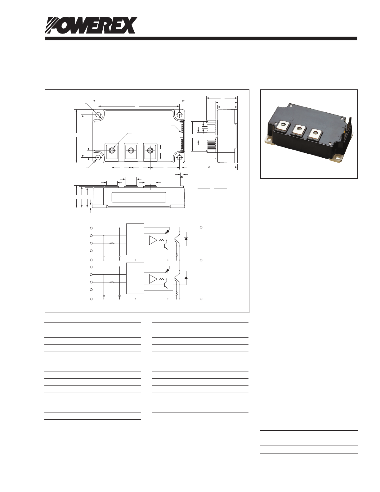
Outline Drawing and Circuit Diagram
Dimensions Inches Millimeters
A 4.72 120.0
B 2.76 70.0
C 1.14 +0.04/-0.02 29.0 +1.0/-0.5
D 4.17±0.010 106.0±0.25
E 2.20±0.010 56.0±0.25
F 0.37 9.3
G 0.98 25.0
H 1.50 38.0
J 0.12±0.02 3.0±0.5
K 0.26 Rad. 6.5 Rad.
L 0.26 Dia. 6.5 Dia.
M M6 Metric M6
Dimensions Inches Millimeters
P 1.59 40.5
Q 1.14 29.0
R 1.02 26.0
S 1.52 38.5
T 0.10 2.54
U 0.40 10.16
V 1.54 39.0
W 1.10 28.0
X 0.14 3.5
Y 0.55 14.0
Z 0.14 Dia. 3.5 Dia.
AA 0.72 18.3
N 0.025 Sq. 0.64 Sq.
Intellimod™ Module
Single Phase
IGBT Inverter Output
450 Amperes/1200 Volts
Description:
Powerex Intellimod™ Intelligent
Power Modules are isolated base
modules designed for power
switching applications operating
at frequencies to 20kHz. Built-in
control circuits provide optimum
gate drive and protection for the
IGBT and free-wheel diode
power devices.
Features:
£ Complete Output Power
Circuit
£ Gate Drive Circuit
£ Protection Logic
– Short Circuit
– Over Temperature
– Under Voltage
Applications:
£ Inverters
£ UPS
£ Motion/Servo Control
£ Power Supplies
Ordering Information:
Example: Select the complete
part number from the table below
-i.e. PM450DV1A120 is a 1200V,
450 Ampere Intellimod™ Intelligent
Power Module.
Type Current Rating V
Amperes Volts (x 10)
PM 450 120
CES
08/12 Rev. 1
1

Powerex, Inc ., 173 Pavilion Lane, Youngwood, Pennsylvania 15697 (724) 925-7272 www.pwrx.com
PM450DV1A120
Intellimod™ Module
Single Phase IGBT Inverter Output
450 Amperes/1200 Volts
Absolute Maximum Ratings, Tj = 25°C unless otherwise specified
Characteristics Symbol PM450DV1A120 Units
Power Device Junction Temperature Tj -20 to 150 °C
Storage Temperature T
-40 to 125 °C
stg
Case Operating Temperature TC -20 to 100 °C
Mounting Torque, M6 Mounting Screws (Typical) — 43 in-lb
Mounting Torque, M6 Main Terminal Screws (Typical) — 43 in-lb
Module Weight (Typical) — 510 Grams
Supply Voltage Protected by SC (VD = 13.5 ~16.5V, Inverter Part, Tj = 125°C Start) V
Surge Supply Voltage (Applied between C1-E2, Surge Value) V
CC(surge)
Isolation Voltage, (60Hz, Sinusoidal, Charged Part to Base, AC 1 minute) V
800 Volts
CC(prot)
1000 Volts
2500 Volts
RMS
Inverter Sector
Collector-Emitter Voltage (VD = 15V, V
Collector Current (TC = 25°C) IC 450 Amperes
Peak Collector Current (Pulse) I
Emitter Current (TC = 25°C) IE 450 Amperes
Peak Emitter Current (Pulse) I
Total Power Dissipation (TC = 25°C)
= 15V) V
CIN
1
*
P
1200 Volts
CES
900 Amperes
CRM
900 Amperes
ERM
2232 Watts
tot
Control Sector
Supply Voltage (Applied Between VP1-VPC, VN1-VNC) VD 20 Volts
Input Voltage (Applied Between CP1-VPC, VN1-VNC) V
Fault Output Supply Voltage (Applied Between FPO-VPC, FNO-VNC) VFO 20 Volts
Fault Output Current (Sink Current at FPO, FNO Terminals) IFO 20 mA
*1 Case temperature (TC) measured point is just under the chips.
20 Volts
CIN
2
08/12 Rev. 1

Powerex, Inc ., 173 Pavilion Lane, Youngwood, Pennsylvania 15697 (724) 925-7272 www.pwrx.com
PM450DV1A120
Intellimod™ Module
Single Phase IGBT Inverter Output
450 Amperes/1200 Volts
Electrical and Mechanical Characteristics, Tj = 25°C unless otherwise specied
Characteristics Symbol Test Conditions Min. Typ. Max. Units
IGBT Inverter Sector
Collector-Emitter Saturation Voltage V
Pulsed, Tj = 25°C
VD = 15V, V
Pulsed, Tj = 125°C
Emitter-Collector Voltage VEC IE = 450A, VD = 15V, V
Switching Times ton VD = 15V, V
trr VCC = 600V, IC = 450A, — 0.3 0.8 µs
t
t
t
Collector-Emitter Cutoff Current I
V
VCE = V
V
VD = 15V, V
CE(sat)
Tj = 125°C, — 0.4 1.0 µs
C(on)
Inductive Load — 2.4 3.3 µs
off
(Per 1 Arm) — 0.4 1.2 µs
C(off)
VCE = V
CES
CIN
= 0V, IC = 450A, — 1.65 2.15 Volts
CIN
= 0V, IC = 450A, — 1.85 2.35 Volts
CIN
= 15V — 2.3 3.3 Volts
CIN
= 0 ~ 15V, 0.3 0.8 2.0 µs
CIN
, VD = 15V, — — 1.0 mA
CES
= 15, Tj = 25°C
CIN
, VD = 15V, — — 10.0 mA
CES
= 15, Tj = 125°C
Control Sector
Circuit Current ID VD = 15V, V
VD = 15V, V
Input ON Threshold Voltage V
Input OFF Threshold Voltage V
Applied Between 1.2 1.5 1.8 Volts
th(on)
CP1-VPC, CN1-VNC 1.7 2.0 2.3 Volts
th(off)
Short Circuit Trip Level SC -20°C ≤ Tj ≤ 125°C, VD = 15V 675 — — Amperes
Short Circuit Current Delay Time t
VD = 15V — 0.2 — µs
off(SC)
Over Temperature Protection OT Trip Level 135 — — °C
(Detect Temperature of Chip) OT
Reset Level — 20 — °C
(hys)
Supply Circuit Under Voltage Protection UV Trip Level 11.5 12.0 12.5 Volts
(Tj ≤ 125°C) UVr Hysteresis — 12.5 — Volts
Fault Output Current I
I
Fault Output Pulse Width tFO VD = 15V
*2 Fault output is given only when the internal SC, OT and UV protection.
Fault output of SC, OT and UV protection operate by lower arms.
Fault output of SC protecton given pulse.
Fault output of OT, UV protection given pulse while over trip level.
VD = 15V, VFO = 15V
FO(H)
VD = 15V, VFO = 15V
FO(L)
= 15V, VP1-VPC — 2 4 mA
CIN
= 15V, VN1-VNC — 2 4 mA
CIN
2
*
— — 0.01 mA
2
*
— 10 15 mA
2
*
1.0 1.8 — ms
08/12 Rev. 1
3

Powerex, Inc ., 173 Pavilion Lane, Youngwood, Pennsylvania 15697 (724) 925-7272 www.pwrx.com
PM450DV1A120
Intellimod™ Module
Single Phase IGBT Inverter Output
450 Amperes/1200 Volts
Thermal Characteristics
Characteristic Symbol Condition Min. Typ. Max. Units
1
Junction to Case Thermal Resistance R
R
Contact Thermal Resistance R
Inverter IGBT (Per 1 Element)
th(j-c)Q
Inverter FWDi (Per 1 Element)
th(j-c)D
Case to Heatsink (Per 1 Module), — 0.018 — K/Watt
th(c-s)
Thermal Grease Applied
*
— — 0.056 K/Watt
1
*
— — 0.079 K/Watt
1
*
Recommended Conditions for Use
Characteristic Symbol Condition Value Units
Supply Voltage V
CC
Control Supply Voltage VD Applied Between VP1-VPC, VN1-V
Input ON Voltage V
Input OFF Voltage V
PWM Input Frequency f
Arm Shoot-Through Blocking Time t
*1 Case temperature (TC) measured point is just under the chips.
*3 With ripple satisfying the following conditions: dv/dt swing ≤ ±5V/µs, variation ≤ 2V peak to peak.
Applied Between ≤ 0.8 Volts
CIN(on)
CP1-VPC, CN1-VNC ≥ 4.0 Volts
CIN(off)
Using Application Circuit ≤ 20 kHz
PWM
For IPM’s each Input Signal ≥ 3.5 µs
DEAD
Applied Across C1-E2 Terminals ≤ 800 Volts
3
*
15 ±1.5 Volts
NC
4
08/12 Rev. 1
Powerex, Inc ., 173 Pavilion Lane, Youngwood, Pennsylvania 15697 (724) 925-7272 www.pwrx.com
PM450DV1A120
Intellimod™ Module
Single Phase IGBT Inverter Output
450 Amperes/1200 Volts
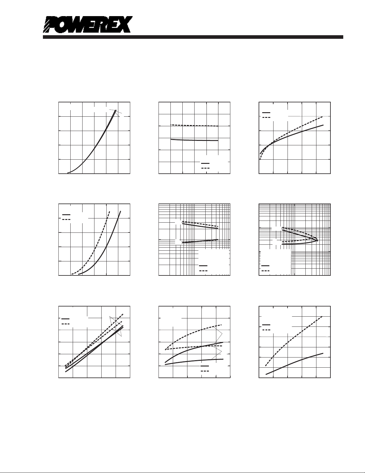
OUTPUT CHARACTERISTICS
(TYPICAL)
500
Tj = 25°C
VD = 17V
400
, (AMPERES)
C
300
200
100
COLLECTOR CURRENT, I
0
0.5 1.0 1.5 2.0
COLLECTOR-EMITTER VOLTAGE, V
DIODE FORWARD CHARACTERISTICS
(TYPICAL)
CE(sat)
500
VD = 15V
400
, (AMPERES)
C
Tj = 25°C
= 125°C
T
j
300
200
100
COLLECTOR RECOVERY CURRENT, -I
0
0 1.0 3.02.0
EMITTER-COLLECTOR VOLTAGE, VEC, (VOLTS)
VCC = 600V
V
= 15V
D
Tj = 25°C
= 125°C
T
j
SWITCHING LOSS
(TYPICAL)
E
on
COLLECTOR CURRENT CHARACTERISTICS
60
50
, (mJ/PULSE)
40
off
, E
on
30
20
10
SWITCHING ENERGY, E
0
0 300 400100 200 500
COLLECTOR CURRENT, I
, (AMPERES)
C
13
15
, (VOLTS)
E
off
SATURATON VOLTAGE CHARACTERISTICS
COLLECTOR-EMITTER
(TYPICAL)
2.5
2.0
, (VOLTS)
CE(SAT)
V
1.5
IC = 450A
Tj = 25°C
= 125°C
T
COLLECTOR-EMITTER SATURATION VOLTAGE,
1.0
12 1413 15 1716 18
CONTROL SUPPLY VOLTAGE, VD, (VOLTS)
COLLECTOR CURRENT CHARACTERISTICS
1
10
, (μs)
off
, t
on
0
10
SWITCHING TIMES, t
SWITCHING TIME VS.
(TYPICAL)
t
off
t
on
j
VCC = 600V
V
= 15V
D
INDUCTIVE LOAD
Tj = 25°C
= 125°C
T
-1
10
1
10
COLLECTOR CURRENT, IC, (AMPERES)
REVERSE RECOVERY CHARACTERISTICS
0.6
VCC = 600V
V
= 15V
D
0.5
INDUCTIVE
, (S)
rr
LOAD
10
(TYPICAL)
0.4 200
j
2
I
rr
0.3 150
t
T
= 25°C
j
= 125°C
T
j
rr
0.2 100
REVERSE RECOVERY TIME, t
0.1
0
0 300 400200100 500
EMITTER CURRENT, IE, (AMPERES)
SATURATION VOLTAGE CHARACTERISTICS
2.5
, (VOLTS)
2.0
CE(SAT)
1.5
1.0
0.5
0
COLLECTOR-EMITTER VOLTAGE, V
COLLECTOR CURRENT CHARACTERISTICS
1
10
, (μs)
c(off)
0
, t
10
c(on)
-1
10
SWITCHING TIMES, t
-2
10
3
10
300
250
10
35
30
, (AMPERES)
rr
25
, (mJ/PULSE)
rr
20
15
10
50
SWITCHING LOSS, E
5
REVERSE RECOVERY CURRENT, I
0
0
(TYPICAL)
VD = 15V
Tj = 25°C
= 125°C
T
j
0 100 200 300 400 500
COLLECTOR CURRENT, IC, (AMPERES)
SWITCHING TIME VS.
(TYPICAL)
t
c(off)
t
c(on)
VCC = 600V
V
= 15V
D
INDUCTIVE LOAD
T
= 25°C
j
= 125°C
T
j
1
COLLECTOR CURRENT, IC, (AMPERES)
SWITCHING REVERSE RECOVERY
LOSS CHARACTERISTICS
VCC = 600V
V
= 15V
D
INDUCTIVE LOAD
T
= 25°C
j
= 125°C
T
j
0 300 400200100 500
EMITTER CURRENT, IE, (AMPERES)
2
10
(TYPICAL)
10
3
08/12 Rev. 1
5

Powerex, Inc ., 173 Pavilion Lane, Youngwood, Pennsylvania 15697 (724) 925-7272 www.pwrx.com
PM450DV1A120
Intellimod™ Module
Single Phase IGBT Inverter Output
450 Amperes/1200 Volts
CIRCUIT CURRENT VS.
FREQUENCY CURRENT
(TYPICAL)
120
VD = 15V
100
Tj = 25°C
= 125°C
T
j
80
60
40
CIRCUIT CURRENT, (mA)
20
0
th(j-c)
10
10
(NORMALIZED VALUE)
•
th
10
= R
th
Z
10
NORMALIZED TRANSIENT THERMAL IMPEDANCE, Z
50 15 2010 25
FREQUENCY CURRENT, fc, (kHz)
TRANSIENT THERMAL
IMPEDANCE CHARACTERISTICS
-3
10
0
-1
-2
Single Pulse
T
= 25°C
C
Per Unit Base =
= 0.056 K/W
R
th(j-c)
-3
(IGBT)
-2
10
10
10
-1
10
-5
10
CONTROL SUPPLY VOLTAGE TRIP-RESET
LEVEL TEMPERATURE DEPENDANCY
20
VD = 15V
16
, (VOLTS)
r
, UV
t
12
8
4
TRIP RESET LEVEL, UV
SUPPLY CIRCUIT UNDER VOLTAGE PROTECTION
0
IMPEDANCE CHARACTERISTICS
0
1
10
-4
-3
10
-3
10
0
th(j-c)
10
-1
10
(NORMALIZED VALUE)
•
-2
th
10
Single Pulse
= R
th
T
= 25°C
Z
C
Per Unit Base =
= 0.079 K/W
R
th(j-c)
-3
10
NORMALIZED TRANSIENT THERMAL IMPEDANCE, Z
(TYPICAL)
UV
t
UV
r
0-50 10050 150
JUNCTION TEMPERATURE, Tj, (°C)
TRANSIENT THERMAL
(FWDi)
-2
-1
10
10
10
TIME, (s)TIME, (s)
0
10
-5
-4
10
2.0
= 25°C) = 1.0
j
1.6
1.2
0.8
0.4
SHORT CIRCUIT CURRENT TRIP LEVEL, (T
1
10
-3
10
SHORT CIRCUIT TRIP LEVEL
VS. JUNCTION TEMPERATURE
(TYPICAL)
VD = 15V
0
0-50 10050 150
JUNCTION TEMPERATURE, Tj, (°C)
6
08/12 Rev. 1
 Loading...