

Page 1
PM25RL1C120
Powerex, Inc., 173 Pavilion Lane, Youngwood, Pennsylvania 15697 (724) 925-7272
www.pwrx.com
A
D
F
E
G
B
C
U (19 TYP.)
S
T
W X
F
VNCWNVN1V
Br
O
1.5k 1.5k1.5k1.5k
O
IN
F
CC
V
OT
SIGND GND
OUT
F
G
G
G
G
1 5 9 13
B P N U V W
L L
O
IN
F
CC
V
OT
SIGND GND
OUT
G
G
N
O
IN
F
V
OT
SIGND GND
OUT
F
F
G
G
G
G
G
H (2 TYP.)
LF
V
V
WPC
U
N
O
IN
F
CC
CC
V
OT
SIGND GND
OUT
G
G
J
K
Q
LL
N
P
M
R
TERMINAL
CODE
C
Z
Y
W
V
V
V
FO
VPC
WP1
OT
FO
V
V
P
VP1
O
IN
F
CC
V
OT
SIGND GND
OUT
VWNB
W
V
P
O
IN
F
SIGND GND
OUT
U
UPC
FO
U
V
P
UP1
O
IN
F
CC
V
OT
SIGND GND
OUT
PU
1 VUPC
2 UFO
3 UP
4 VUP1
5 VVPC
6 VFO
7 VP
8 VVP1
9 VWPC
10 WFO
11 W P
12 VWP1
CC
V
13 VNC
14 VN1
15 Br
16 UN
17 VN
N
18 W
19 FO
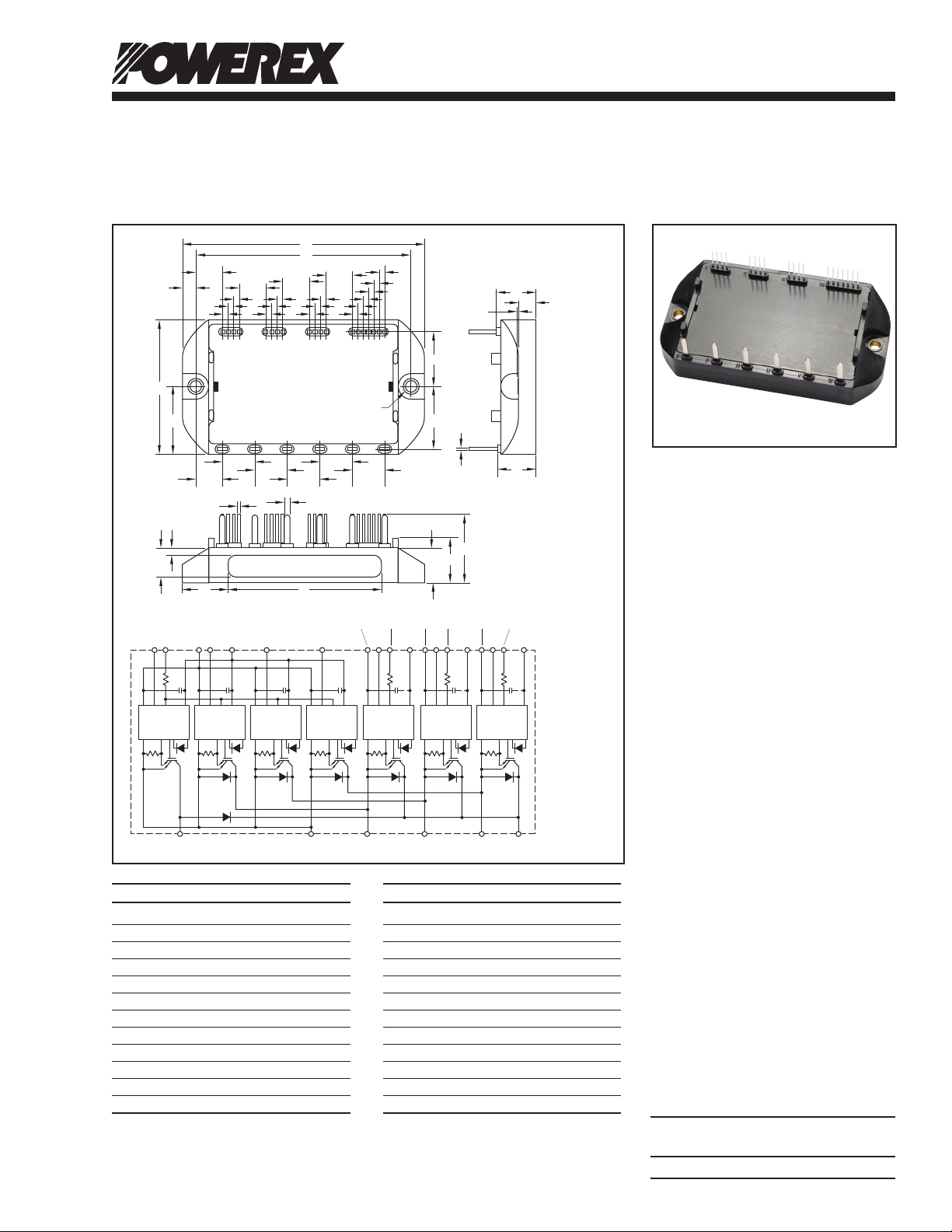
Outline Drawing and Circuit Diagram
Dim. Inches Millimeters
A 3.54 90.0
B 1.97 50.0
C 0.98 25.0
D 3.5 80.0
E 0.2 5.0
F 0.4 10.0
G 0.08 2.0
H 0.17 Dia. 4.3 Dia.
J 0.8 20.5
K 0.9 23.0
L 0.47 12.0
M 0.012 0.3
Dim. Inches Millimeters
N 0.58 14.6
P 0.26 6.7
Q 0.02 0.5
R 0.56 14.2
S 0.1±0.02 2.5±0.5
T 0.31 8.0
U 0.02 Sq. 0.5 Sq.
V 0.08 2.0
W 0.69±0.02 17.5±0.5
X 2.20 55.0
Y 0.52 13.0
Z 0.65 16.5
Intellimod™ L1-Series
Three Phase
IGBT Inverter + Brake
25 Amperes/1200 Volts
Description:
Powerex Intellimod™ Intelligent
Power Modules are isolated base
modules designed for power
switching applications operating
at frequencies to 20kHz. Built-in
control circuits provide optimum
gate drive and protection for the
IGBT and free-wheel diode
power devices.
Features:
£ Complete Output Power
Circuit
£ Gate Drive Circuit
£ Protection Logic
– Short Circuit
– Over Temperature
Using On-chip
Temperature Sensing
– Under Voltage
£ Low Loss Using Full Gate
CSTBT™ IGBT Chip
Applications:
£ Inverters
£ UPS
£ Motion/Servo Control
£ Power Supplies
Ordering Information:
Example: Select the complete
part number from the table below
-i.e. PM25RL1C120 is a 1200V,
25 Ampere Intellimod™ Intelligent
Power Module.
Type Current Rating V
Amperes Volts (x 10)
PM 25 120
CES
04/130 Rev. 2
1
Page 2

Powerex, Inc., 173 Pavilion Lane, Youngwood, Pennsylvania 15697 (724) 925-7272 www.pwrx.com
PM25RL1C120
Intellimod™ L1-Series
Three Phase IGBT Inverter + Brake
25 Amperes/1200 Volts
Absolute Maximum Ratings, Tj = 25°C unless otherwise specied
Characteristics Symbol PM25RL1C120 Units
Power Device Junction Temperature Tj -20 to 150 °C
Storage Temperature T
-40 to 125 °C
stg
Mounting Torque, M4 Mounting Screws — 15 in-lb
Module Weight (Typical) — 150 Grams
Supply Voltage, Surge (Applied between P - N) V
Self-protection Supply Voltage Limit (Short Circuit protection Capability)* V
CC(surge)
CC(prot.)
Isolation Voltage, AC 1 minute, 60Hz Sinusoidal V
1000 Volts
800 Volts
2500 Volts
ISO
IGBT Inverter Sector
Collector-Emitter Voltage (VD = 15V, V
Collector Current (TC = 25°C) (Note 1) ±IC 25 Amperes
Peak Collector Current (TC = 25°C) ±ICP 50 Amperes
Collector Dissipation (TC = 25°C) (Note 1) PC 178 Watts
= 15V) V
CIN
1200 Volts
CES
IGBT Brake Sector
Collector-Emitter Voltage (VD = 15V, V
Collector Current (TC = 25°C) (Note 1) ±IC 25 Amperes
Peak Collector Current (TC = 25°C) ±ICP 50 Amperes
Collector Dissipation (TC = 25°C) (Note 1) PC 178 Watts
Diode Forward Current (TC = 25°C) IF 25 Amperes
Diode Rated DC Reverse Voltage (TC = 25°C) V
= 15V) V
CIN
1200 Volts
CES
1200 Volts
R(DC)
Control Sector
Supply Voltage (Applied between V
UP1-VUPC
Input Voltage (Applied between UP-V
Fault Output Supply Voltage VFO 20 Volts
(Applied between UFO-V
UPC
, VFO-V
Fault Output Current (UFO, VFO, WFO, FO Terminals) IFO 20 mA
*VD = 13.5 ~ 16.5V, Inverter Part, Tj = 125°C
UPC
VPC
, V
, VP-V
, WFO-V
VP1-VVPC
VPC
, WP-V
WPC
, V
WP1-VWPC
WPC
, FO-VNC)
, VN1-VNC) VD 20 Volts
, UN- VN- WN-Br-VNC) V
Note 1:TC (under the chip) Measurement Point
Y
BOTTOM VIEW
X(0,0)
20 Volts
CIN
Arm UP VP WP UN VN WN Br
Axis IGBT FWDi IGBT FWDi IGBT FWDi IGBT FWDi IGBT FWDi IGBT FWDi IGBT FWDi
X 49.0 49.0 35.0 35.0 21.0 21.0 42.0 42.0 28.0 28.0 14.0 14.0 64.0 67.8
Y 2.4 -4.4 2.4 -4.4 2.4 -4.4 -6.9 -0.05 -6.9 -0.05 -4.9 2.0 4.3 -4.6
2
04/13 Rev. 2
Page 3

Powerex, Inc., 173 Pavilion Lane, Youngwood, Pennsylvania 15697 (724) 925-7272 www.pwrx.com
PM25RL1C120
Intellimod™ L1-Series
Three Phase IGBT Inverter + Brake
25 Amperes/1200 Volts
Electrical and Mechanical Characteristics, Tj = 25°C unless otherwise specied
Characteristics Symbol Test Conditions Min. Typ. Max. Units
IGBT Inverter Sector
Collector-Emitter Saturation Voltage V
Tj = 25°C
VD = 15V, V
Tj = 125°C
Diode Forward Voltage VEC -IC = 25A, V
Inductive Load Switching Times ton — 1.0 — µs
trr VD = 15V, V
t
t
t
Collector-Emitter Cutoff Current I
VCE = V
VD = 15V, V
CE(sat)
VCC = 600V, IC = 25A — 0.4 — µs
C(on)
Tj = 125°C — 2.0 — µs
off
— 0.7 — µs
C(off)
VCE = V
CES
CES
= 0V, IC = 25A, — 1.55 — Volts
CIN
= 0V, IC = 25A, — 1.75 — Volts
CIN
= 15V, VD = 15V — 2.3 — Volts
CIN
= 0 ⇔ 15V — 0.5 — µs
CIN
, VD = 15V, Tj = 25°C — — 1.0 mA
CES
, VD = 15V, Tj = 125°C — — 10 mA
IGBT Brake Sector
Collector-Emitter Saturation Voltage V
Tj = 25°C
VD = 15V, V
Tj = 125°C
Forward Voltage VFM IF = 25A — 2.3 — Volts
Collector-Emitter Cutoff Current I
VCE = V
VD = 15V, V
CE(sat)
VCE = V
CES
= 0V, IC = 25A, — 1.55 — Volts
CIN
= 0V, IC = 25A, — 1.75 — Volts
CIN
, VD = 15V, Tj = 25°C — — 1.0 mA
CES
, VD = 15V, Tj = 125°C — — 10 mA
CES
Control Sector
Circuit Current ID VD = 15V, V
VD = 15V, V
Input ON Threshold Voltage V
Input OFF Threshold Voltage V
Applied between UP-V
th(on)
th(off)
VP-V
VPC
, WP-V
Short Circuit Trip Level SC Inverter Part 50 — — Amperes
(-20°C ≤ Tj ≤ 125°C, VD = 15V) Brake Part 50 — — Amperes
Short Circuit Current Delay Time t
VD = 15V — 0.2 — µs
off(SC)
Over Temperature Protection OT Trip Level 135 145 — °C
(Detect Tj of IGBT Chip) OTR Reset Level — 125 — °C
Supply Circuit Under-voltage Protection UV Trip Level 11.5 12.0 12.5 Volts
(-20 ≤ Tj ≤ 125°C) UVR Reset Level 12.0 12.5 13.0 Volts
Fault Output Current* I
I
VD = 15V, V
FO(H)
VD = 15V, V
FO(L)
Minimum Fault Output Pulse Width* tFO VD = 15V 1.0 1.8 — ms
*Fault output is given only when the inter nal SC, OT and UV protections schemes of either upper or lower arm device operates to protect it.
= 15V, VN1-VNC — 20 30 mA
CIN
= 15V, V
CIN
WPC
*P1-V*PC
, UN- VN- WN-Br-VNC 1.7 2.0 2.3 Volts
= 15V — — 0.01 mA
CIN
= 15V — 10 15 mA
CIN
— 5 10 mA
, 1.2 1.5 1.8 Volts
UPC
04/13 Rev. 2
3
Page 4

Powerex, Inc., 173 Pavilion Lane, Youngwood, Pennsylvania 15697 (724) 925-7272 www.pwrx.com
PM25RL1C120
Intellimod™ L1-Series
Three Phase IGBT Inverter + Brake
25 Amperes/1200 Volts
Electrical and Mechanical Characteristics, Tj = 25°C unless otherwise specied
Characteristics Symbol Test Conditions Min. Typ. Max. Units
Thermal Characteristics, Tj = 25°C unless otherwise specied
Characteristic Symbol Condition Min. Typ. Max. Units
Junction to Case Thermal Resistance R
Inverter Part R
Junction to Case Thermal Resistance R
Brake Part R
Contact Thermal Resistance R
IGBT (Per 1 Element) (Note 1) — — 0.70* °C/Watt
th(j-c)Q
FWDi (Per 1 Element) (Note 1) — — 1.18* °C/Watt
th(j-c)D
IGBT (Note 1) — — 0.70* °C/Watt
th(j-c)Q
FWDi (Note 1) — — 1.18* °C/Watt
th(j-c)D
Case to Fin Per Module, — — 0.085 °C/Watt
th(c-f)
Thermal Grease Applied) (Note 1)
Recommended Conditions for Use
Characteristic Symbol Condition Value Units
Supply Voltage VCC Applied across P-N Terminals ≤800 Volts
Control Supply Voltage** VD Applied between V
V
Input ON Voltage V
Input OFF Voltage V
PWM Input Frequency f
Arm Shoot-through Blocking Time t
* If you use this value, R
** With ripple satisfying the following conditions: dv/dt swing ≤ ±5V/µs, Variation ≤ 2V peak to peak.
should be measured just under the chips.
th(f-a)
Applied between UP-V
CIN(on)
VP-V
CIN(off)
— ≤20 kHz
PWM
Input Signal ≥2.5 µs
DEAD
VP1-VVPC
VPC
, V
WP1-VWPC, VN1-VNC
, WP-V
, UN- VN- WN-Br-VNC ≥9.0 Volts
WPC
UP1-VUPC
, 15.0 ±1.5 Volts
, ≤0.8 Volts
UPC
4
04/13 Rev. 2
 Loading...