

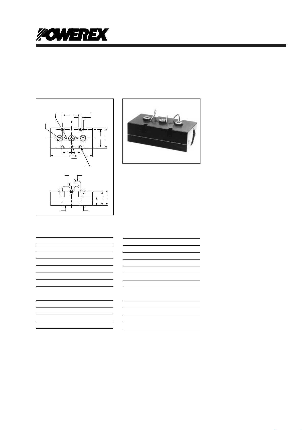
Z9A Outline
Dimension Inches Millimeters
A 7.50 190.50
B 3.70 93.98
C 3.15 80.01
D 3.15 80.01
E 0.328 Dia. Dia. 8.33
F 2.03 51.56
G 3/8-16 3/8-16
UNC-2B UNC-2B
H 1.51 38.35
J 2.52 64.00
K 2.75 69.85
L 0.56 14.22
Ordering Information:
Select the complete thirteen digit
module part number you desire
from the Configuration Reference
Description.
Example: P3Z7ACT700W16 is a
1600 Volt, 375 Ampere Average,
Dual SCR POW-R-BRIK™ Module
with the standard thermistor.
Z7A Outline
Dimension Inches Millimeters
A 6.30 153.16
B 3.02 76.70
C 3.15 80.01
D 2.47 62.73
E 0.328 Dia. Dia. 8.33
F 1.83 46.48
G 5/16-18 5/16-18
UNC-2B UNC-2B
H 1.27 32.25
J 2.09 53.08
K 2.25 57.15
L 0.56 14.22
Mounting Bolt (E) Torque Limit is 11 ft.-lb.
Electrical terminal (G) torque limit is 11 ft.-lb. for type
Z7A and 20 ft.-lb.for Z9A.
Apply a thin coating of thermal joint compound to heat
sink surface prior to module mounting.
Module weights: Z7A weighs 6 lbs. while the Z9A module
weighs 11 lbs.
If incoming tests are done for isolation voltage, the volt-
age should be applied in a slow manner rather than
abruptly imposed on the device.The voltage should be
applied between the top terminals, which must be shorted
together, and the metal case.
The metal case is anodized and provides added voltage
isolation capability if not damaged: factory hi-pot test is
achieved without the benefit of the anodized coating.
Description:
Powerex POW-R-BRIK™ Modules
are designed for medium and high
current power control applications.
POW-R-BRIK™ Modules feature
an electrically isolated package
that simplifies system packaging,
installation and cooling.
POW-R-BRIK™ Modules utilize
Compression Bonded
Encapsulation (CBE) mounting
and double side cooling of the
semiconductor elements.The Z7A
outline POW-R-BRIK™ uses
33mm or 38mm elements and the
Z9A outline POW-R-BRIK™ uses
50mm elements. Standard circuit
configurations include Dual SCR,
Dual Diode, SCR/Diode, and
Diode/SCR. Additional circuit configurations, e.g.Single Element,
Common Cathode, Common
Anode, and special element types,
e.g. Fast Switch SCRs, Fast
Recovery Diodes, GTOs, and
Transistors are available.
Features:
M Electrically Isolated Packaging
M Anodized Aluminum Housing
M Internal Copper Contacting
M Gold Element Contacting
M Internal Temperature Sensor
M Compression Element
Contacting
Applications:
M AC Motor Star ters
M DC Motor Controls
M Resistance Welding Controls
M Mining Power Centers
M High Voltage Motor Starters
M Transportation Systems
P-1
Powerex,Inc., 200 Hillis Street, Youngwood, Pennsylvania 15697-1800 (724) 925-7272
Phase Control Modules
345-800 Amperes/400-3000 Volts
POW-R-BRIK™
POW-R-BRIK™
Phase Control Modules
345-800 Amperes/400-3000 Volts
Outline Drawing
B
D
F
F
X2 A2K1
A
K
J
H
E Ø THRU HOLE TYP. 4 PLACES
(FOR TYP. 1/4-20 SOCKET HD. SCR.)
(& BELLEVILLE SPRING WASHER)
MARKING: STYLE NO. WITH DATE
CODE & MFG. LOCATION CODE
(CUSTOMER PART NO. OPTIONAL)
SENSOR (WHITE) LEADS
12.5 ±0.5" LONG WITH
0.375" IN LONG STRIPED ENDS
GATE (WHITE) & CATHODE
(RED) LEADS 12.5" LONG
WITH 0.375" LONG
STRIPPED ENDS
THIS SURFACE
MUST BE PROTECTED
AND NOT DAMAGED
C
C
L
C
L
L TYP. 4 PLACES
MARKING: K1
AI/K2 (ANODE)/(CATHODE),
AND A2 (ANODE) AS SHOWN
OUTLINE DRAWING
MARKING: DEVICE
AND DIRECTION
ACCORDING TO CIRCUIT
CONFIGURATION CHART
G TAPPED HOLE
x 0.50 DEEP
TYP. 3 PLACES
CASE ANODIZED PER
MIL-A-8625, TYPE II
C
L
P-2
Powerex,Inc., 200 Hillis Street, Youngwood, Pennsylvania 15697-1800 (724) 925-7272
POW-R-BRIK™
Phase Control Modules
345-800 Amperes/400-3000 Volts
Configuration Reference:
The POW-R-BRIK™part number
system takes the form
P3 Z7A
CT7 00 W16
where:
•
P3
is the configuration number.
The configurations are shown
pictorially in the right hand
column.
•
Z7A
is the package type per
the outline drawings Z7A and
Z9A on this data sheet.
•
CT7
denotes the element code.
The Element Code Reference
at the end of this data sheet
provides information on the
standard element codes
including the corresponding
disc device using the element.
Refer to the appropriate disc
package data sheets in the
Powerex Semiconductor Data
Book for additional device
specifications.
•
00
denotes special features:
00 – module includes
standard thermistor
XT – no thermistor
AA-ZZ – denotes unique
customer specification
•
W16
denotes voltage code per
the table below.Note that not
all voltage ratings are available
for every element.Refer to the
Element Code Reference for
available voltage ranges for a
given element.
Elements Voltage
Voltage Rating Code
400 V04
600 V06
800 V08
1000 W10
1200 W12
1400 W14
1600 W16
1800 W18
2000 W20
2200 W22
2400 W24
2600 W26
2800 W28
3000 W30
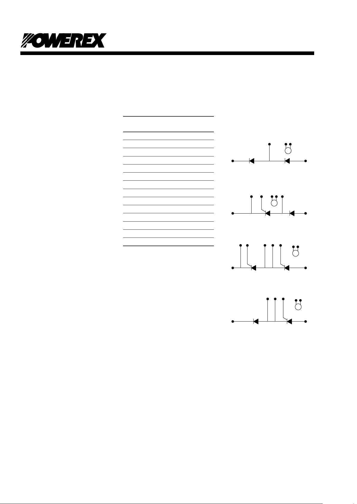
S
S
Element 1
S
S
Element 2
Element 1 Element 2
Element 1 Element 2
Element 1 Element 2
P1 - DIODE
P4 - FAST DIODE*
P2 - SCR/DIODE
P5 - FAST SCR/FAST DIODE*
P3 - SCR/SCR
P6 - FAST SCR/FAST SCR*
P7 - DIODE/SCR
P8 - FAST DIODE/FAST SCR*
* Consult Factory for Available Ratings.
Circuit Configurations:

Powerex,Inc., 200 Hillis Street, Youngwood, Pennsylvania 15697-1800 (724) 925-7272
POW-R-BRIK™
Phase Control Modules
345-800 Amperes/400-3000 Volts
P-3
Typical Thermistor Circuit
Thermistor temperatures can be
measured using the following
circuit arrangement in conjunction
with a 5 volt source.Resistance
values for R1and R2are specified
for two operating temperature
ranges.
POW-R-BRIK™Thermistor
Characteristics
Element
Average
ThermistorThermistor Temperature
Resistance Temp.Steady State Dynamic
Ohms °C °C (Min.) °C (Max.)
➀➁➂
12093 40 43 50
7337 50 53 60
4990 60 63 70
3324 70 73 80
2262 80 83 90
1569 90 93 100
1316 95 98 105
1109 100 103 110
938 105 108 115
797 110 113 120
680 115 118 125
582 120 123 130
500 125 128 135
431 130 133 140
➀Curve matched ±2% over temperature range of +40°C
to +125°C.Resistance tolerance specified at +125°C,
±6%.
➁Without self heating, 10mW maximum thermistor
dissipation.
➂Use “Sensor at Tj”ohms from characteristics for
recommended steady state overload trip resistance.
1.Temperature range, 75°C
through 125°C
R1= 3.5K ohms
R2= 840 ohms
V0= 2.5 volts at 100°C
2.Temperature range, 90°C
through 140°C
R1= 2.2K ohms
R2= 500 ohms
V0= 2.45 volts at 115°C
The output signal (V0) is
approximately 30 mv/°C over the
temperature range indicated.
R
1
R
2
V
O
5 VOLT SUPPLY
THERMISTOR GATES
POW-R-BRIK
CONTROL:
PROTECTION
CIRCUIT
TIME, t, (SECONDS)
TRANSIENT THERMAL IMPEDANCE
CHARACTERISTICS (JUNCTION-TO-CASE)
Z7A
10
-4
TRANSIENT THERMAL IMPEDANCE, Z
u(J-C)
(t), (
o
C/WATT)
10
-1
10
-2
10
-3
10-310-210-110010110210
3
PER ELEMENT,
BOTH CONDUCTING
PER ELEMENT,
ONE CONDUCTING
PER MODULE,
BOTH CONDUCTING
TIME, t, (SECONDS)
TRANSIENT THERMAL IMPEDANCE
CHARACTERISTICS (JUNCTION-TO-CASE)
Z9A
10
-4
TRANSIENT THERMAL IMPEDANCE, Z
u(J-C)
(t), (
o
C/WATT)
10
-1
10
-2
10
-3
10-310-210-110010110210
3
PER ELEMENT,
BOTH CONDUCTING
PER ELEMENT,
ONE CONDUCTING
PER MODULE,
BOTH CONDUCTING

P-4
Powerex,Inc., 200 Hillis Street, Youngwood, Pennsylvania 15697-1800 (724) 925-7272
POW-R-BRIK™
Phase Control Modules
345-800 Amperes/400-3000 Volts
Maximum Ratings and Electrical Characteristics
P1Z7AAR700W_ _
P1Z7ABR700W_ _
P1Z9AAR900W_ _
P1Z9ACR900W_ _
P1Z9ADR900V_ _
3000
2200
3000
1200
600
3000
2500
3000
2500
2500
1.10
0.92
1.70
1.50
1.50
1.00
1.00
1.15
1.15
1.15
3000
2200
3000
1200
600
3100
2300
3100
1300
700
3100
2300
3100
1300
700
300
300
300
300
300
50
50
150
150
150
50
50
150
150
150
7
9
16
30
50
7
9
16
30
50
15
10
20
15
10
—
—
—
—
—
Voltage Gate Current, Speed of Element*
Voltage Gate Current Speed
Isolation
Voltage**
Strike
Distance
V
DRM/VRRM
➀
E1
(V)
Part Number
E2
(V)
I
DRM/IRRM
➀
E1
(mA)E2(mA)
I
TSM/IFSM
➄
E1
(kA)E2(kA)
V
RMS
(V)
I
RMS
(mA)
SCR
t
q
(µs)
Diode
t
rr
(µs)
Terminals
V
RSM
E1
(V)E2(V)
dv/dt➁
(V/µs)
V
GT
(V)
I
GT
(mA)
➀
di/dt➃
(A/µs)
➂
Diode/Diode
2200
1600
3000
2000
1600
2500
2500
3000
2500
2500
0.92
0.92
1.70
1.50
1.50
1.00
1.00
1.15
1.15
1.15
2200
1600
3000
2000
1600
2300
1700
3100
2100
1700
2300
1700
3100
2100
1700
—
—
—
—
—
—
—
—
—
—
—
—
—
—
—
—
—
—
—
—
150
150
200
200
200
600
600
600
600
600
30
30
150
75
75
30
30
150
75
75
9
10
15
17
25
9
14
16
16
16
150
150
400
250
150
10
8
20
20
20
3
3
3
3
3
Half Control SCR/Rectifier
➀
P2Z7ABB700W_ _
P2Z7ACB700W_ _
P2Z9AAA900W_ _
P2Z9ABA900W_ _
P2Z9ACA900W_ _
2200
1600
3000
2200
1400
3000
2000
1600
2500
2500
2500
2500
2500
3000
2500
2500
0.92
0.92
0.92
0.92
0.92
1.70
1.50
1.50
1.00
1.00
1.00
1.00
1.00
1.15
1.15
1.15
2200
1600
3000
2200
1400
3000
2000
1600
2300
1700
3100
2300
1500
3100
2100
1700
2300
1700
3100
2300
1500
3100
2100
1700
300
300
300
300
300
300
300
300
150
150
150
150
150
200
200
200
600
600
600
600
600
600
600
600
30
30
35
35
35
150
75
75
30
30
35
35
35
150
75
75
9
10
9
12
15
15
17
25
9
10
9
12
15
15
17
25
150
150
200
200
200
400
250
150
—
—
—
—
—
—
—
—
3
3
3
3
3
3
3
3
Full Control SCR/SCR
P3Z7ABT700W_ _
P3Z7ACT700W_ _
P3Z7AAT800W_ _
P3Z7ABT800W_ _
P3Z7ACT800W_ _
P3Z9AAT900W_ _
P3Z9ABT900W_ _
P3Z9ACT900W_ _
P7Z7ABB700W_ _
P7Z7ABC700W_ _
P7Z9AAA900W_ _
P7Z9AAB900W_ _
P7Z9AAC900W_ _
2200
1600
3000
2000
1600
2500
2500
3000
2500
2500
0.92
0.92
1.70
1.50
1.50
1.00
1.00
1.15
1.15
1.15
0.70
0.70
1.00
1.00
1.00
0.70
0.70
1.00
1.00
1.00
0.70
0.70
0.70
0.70
0.70
1.00
1.00
1.00
0.70
0.70
1.00
1.00
1.00
2200
1600
3000
2000
1600
2300
1700
3100
2100
1700
2300
1700
3100
2100
1700
300
300
300
300
300
150
150
200
200
200
600
600
600
600
600
30
30
150
75
75
30
30
150
75
75
9
14
16
16
16
9
10
15
17
25
150
150
400
250
150
10
8
20
20
20
3
3
3
3
3
Half Control Rectifier/SCR
➇
Applies for zero or negative gate bias.
Higher dv/dt ratings available, consult factory.
With recommended gate drive.
Per JEDEC standard RS-397, 5.2.2.6.
Per JEDEC RS-397, 5.2.2.1.
Bottom side cooled.
Consult recommended mounting procedures.
Designs are available for “Current Source Inverter”
applications, consult factory.
Reflects substantial derating necessary with single
0.08°C/W or 0.10°C/W sink.
Element location indicated by E1 or E2.
Hi-Pot. 60Hz, 1 min. test
➀
➁
➂
➃
➄
➅
➆
➇
➈
*
**
to
Case
(In.)
K1/A
1
K2/A
2
(In.)

P-5
Powerex,Inc., 200 Hillis Street, Youngwood, Pennsylvania 15697-1800 (724) 925-7272
POW-R-BRIK™
Phase Control Modules
345-800 Amperes/400-3000 Volts
P1Z7AAR700W_ _
P1Z7ABR700W_ _
P1Z9AAR900W_ _
P1Z9ACR900W_ _
P1Z9ADR900V_ _
355
435
590
740
800
AR7
BR7
AR9
CR9
DR9
AR7
BR7
AR9
CR9
DR9
105
105
105
105
110
1125
1125
1500
1500
1330
150
150
150
150
150
0.04
0.04
0.03
0.03
0.03
0.010
0.010
0.008
0.008
0.008
0.10
0.10
0.08
0.08
0.08
40
40
40
40
40
385
440
570
670
775
400
465
600
705
805
—
—
—
—
—
—
—
—
—
—
315
315
315
315
315
Current and Thermal Ratings of Module
Circuit Currents
Element
Data Model*
I
T(av)
➅
(A)
@T
C
(°C)
Part Number
Units per
Sink→
T
A
(°C)
Maximum
Power
Dissipation
(W)
T
j
(°C)
E1 E2
Sensor
@T
j
(Ω)
R
u(J-C)
per
Module
(°C/W)
1
AC
Switch
I
RMS
(A)
3
AC
Switch
➈
I
RMS
(A)
2
1∅
Bridge
I
DC
(A)
3
3∅
Bridge
➈
I
DC
(A)
R
u(C-S)
per
Module
➆
(°C/W)
R
u(C-A)
(°C/W)
Current Thermal
Diode/Diode
P2Z7ABB700W_ _
P2Z7ACB700W_ _
P2Z9AAA900W_ _
P2Z9ABA900W_ _
P2Z9ACA900W_ _
380
395
430
520
590
350
365
390
460
495
BT7
CT7
AT9
BT9
CT9
BR7
BR7
AR9
AR9
AR9
85
85
85
85
85
1100
1100
1325
1465
1465
130
130
125
130
130
0.04
0.04
0.03
0.03
0.03
0.010
0.010
0.008
0.008
0.008
0.10
0.10
0.08
0.08
0.08
40
40
40
40
40
560
590
630
740
800
275
290
310
365
385
330
345
370
435
470
530
530
640
530
530
Half Control SCR/Diode
➇
P3Z7ABT700W_ _
P3Z7ACT700W_ _
P3Z7AAT800W_ _
P3Z7ABT800W_ _
P3Z7ACT800W_ _
P3Z9AAT900W_ _
P3Z9ABT900W_ _
P3Z9ACT900W_ _
345
375
300
390
450
355
470
600
315
335
265
345
405
330
420
480
BT7
CT7
AT8
BT8
CT8
AT9
BT9
CT9
BT7
CT7
AT8
BT8
CT8
AT9
BT9
CT9
85
85
85
85
85
85
85
85
1095
1095
1095
1095
1095
1295
1460
1460
130
130
130
130
130
125
130
130
0.04
0.04
0.04
0.04
0.04
0.03
0.03
0.03
0.010
0.010
0.010
0.010
0.010
0.008
0.008
0.008
0.10
0.10
0.10
0.10
0.10
0.08
0.08
0.08
40
40
40
40
40
40
40
40
505
550
445
560
630
535
675
815
250
270
220
275
300
260
335
375
300
320
255
330
385
310
400
460
530
530
530
530
530
640
530
530
Full Control SCR/SCR
P7Z7ABB700W_ _
P7Z7ABC700W_ _
P7Z9AAA900W_ _
P7Z9AAB900W_ _
P7Z9AAC900W_ _
380
395
430
520
590
350
365
390
460
495
BR7
BR7
AR9
AR9
AR9
BT7
CT7
AT9
BT9
CT9
85
85
85
85
85
1100
1100
1325
1465
1465
130
130
125
130
130
0.04
0.04
0.03
0.03
0.03
0.010
0.010
0.008
0.008
0.008
0.10
0.10
0.08
0.08
0.08
40
40
40
40
40
560
590
630
740
800
275
290
310
365
385
330
345
370
435
470
530
530
640
530
530
Half Control SCR/Diode
➇
Applies for zero or negative gate bias.
Higher dv/dt ratings available, consult factory.
With recommended gate drive.
Per JEDEC standard RS-397, 5.2.2.6.
Per JEDEC RS-397, 5.2.2.1.
Bottom side cooled.
Consult recommended mounting procedures.
Designs are available for “Current Source Inverter”
applications, consult factory.
Reflects substantial derating necessary with single
0.08°C/W or 0.10°C/W sink.
Reference element data model on the following page.
➀
➁
➂
➃
➄
➅
➆
➇
➈
*

P-6
Powerex,Inc., 200 Hillis Street, Youngwood, Pennsylvania 15697-1800 (724) 925-7272
POW-R-BRIK™
Phase Control Modules
345-800 Amperes/400-3000 Volts
AR7
BR7
CR7
➂
AR9
CR9
DR9
BT7
CT7
AT8
BT8
CT8
AT9
BT9
CT9
9HP
➂
33mm Diode
33mm Diode
33mm Diode
50mm Diode
50mm Diode
50mm Diode
33mm SCR
33mm SCR
38mm SCR
38mm SCR
38mm SCR
50mm SCR
50mm SCR
50mm SCR
50mm SCR
0.00045
0.00013
0.00008
0.00024
0.00005
0.00006
0.000325
0.000416
0.001179
0.00010
-0.00013
0.000620
0.000074
0.000135
0.000225
0.02836
0.02065
0.01128
0.00319
0.00766
0.00061
0.01882
0.00060
-0.03631
0.03081
0.03756
0.01789
0.03286
0.00104
-0.00178
R7S0 _ _ 08XX00
R7S0 _ _ 12XX00
R7S0 _ _ 16XX00
R9G0 _ _ 12XX00
R9G0 _ _ 18XX00
R9G0 _ _ 22XX00
T7S0 _ _ 6504DN
T7S0 _ _ 7504DN
T820 _ _ 6003DH
T820 _ _ 7503DH
T820 _ _ 9003DH
T9G0 _ _ 0803DH
T9G0 _ _ 1003DH
T9G0 _ _ 1203DH
T9GH _ _ 0903DH
2200-3000
1200-2200
800-1200
2200-3000
800-1200
400-800
1400-2200
800-1600
2200-3000
1200-2200
800-1400
2200-3000
1200-2000
800-1600
1200-2200
0.89605
0.63200
0.45000
0.39964
0.60627
0.46319
0.74419
0.58729
1.02841
0.88287
1.08412
1.43303
0.96195
0.55570
0.95642
-0.08108
-0.02192
0.02800
0.05540
-0.00168
0.02950
0.00380
0.06654
0.13475
-0.07743
-0.13881
-0.10092
-0.08755
0.05740
-0.00285
Comparable
Disc Device
Available Voltage
Range
A
B
C
D
Coefficients for V
TM
, VF, Model
➀ ➁
Element
Type
VTM, VF = A + B x LN(I) + C x I + D x I (I = Amps Peak)
Coefficients are for T
j
= 130°C, 50A through 3000A Peak
Module ratings for these elements are not shown, consult factory.
➀
➁
➂
Element
Code
Element Code Reference
 Loading...