

Page 1

Uninterruptible Power Supply System
Powerex OL 1K/2K/3K RM Online UPS Rack
USER MANUAL
GB
Page 2

1
Table of Contents
1. Important Safety Warning………………………………………………
2
1-1. Transportation
2
1-2. Preparation
2
1-3. Installation
2
1-4. Operation
2
1-5. Maintenance, service and faults
3
2. Installation and setup……………………………………………………
4
2-1. Rear panel view
4
2-2. Rack-mounted the UPS
4
2-3. Setup the UPS
5
2-4. Battery replacement
7
2-5. Battery kit assembly (option)
8
3. Operations…………………………………………………………………..
10
3-1. Button operation
10
3-2. LCD Panel
10
3-3. Audible Alarm
12
3-4. LCD display wordings index
12
3-5. UPS Setting
12
3-6. Operating Mode Description
15
3-7. Faults Reference Code
15
3-8. Warning indicator
16
4. Troubleshooting…………………………………………………………...
18
5. Storage and Maintenance……………………………………………….
18
6. Specifications………………………………………………………………
Page 3

2
1. Important Safety Warning
Please comply with all warnings and operating instructions in this manual strictly. Save this
manual properly and read carefully the following instructions before installing the unit. Do not
operate this unit before reading through all safety information and operating instructions
carefully
1.1. Transportation
Please transport the UPS system only in the original package to protect against
shock and impact.
1.2. Preparation
Condensation may occur if the UPS system is moved directly from cold to warm
environment. The UPS system must be absolutely dry before being installed. Please
allow at least two hours for the UPS system to acclimate the environment.
Do not install the UPS system near water or in moist environments.
Do not install the UPS system where it would be exposed to direct sunlight or near
heater.
Do not block ventilation holes in the UPS housing.
1.3. Installation
Do not connect appliances or devices which would overload the UPS system (e.g.
laser printers) to the UPS output sockets.
Place cables in such a way that no one can step on or trip over them.
Do not connect domestic appliances such as hair dryers to UPS output sockets.
The UPS can be operated by any individuals with no previous experience.
Connect the UPS system only to an earthed shockproof outlet which must be easily
accessible and close to the UPS system.
Please use only VDE-tested, CE-marked mains cable (e.g. the mains cable of your
computer) to connect the UPS system to the building wiring outlet (shockproof
outlet).
Please use only VDE-tested, CE-marked power cables to connect the loads to the
UPS system.
When installing the equipment, it should ensure that the sum of the leakage current
of the UPS and the connected devices does not exceed 3.5mA.
1.4. Operation
Do not disconnect the mains cable on the UPS system or the building wiring outlet
(shockproof socket outlet) during operations since this would cancel the protective
earthing of the UPS system and of all connected loads.
The UPS system features its own, internal current source (batteries). The UPS
output sockets or output terminals block may be electrically live even if the UPS
system is not connected to the building wiring outlet.
In order to fully disconnect the UPS system, first press the OFF/Enter button to
disconnect the mains.
Prevent no fluids or other foreign objects from inside of the UPS system.
Page 4

3
1.5. Maintenance, service and faults
The UPS system operates with hazardous voltages. Repairs may be carried out only
by qualified maintenance personnel.
Caution - risk of electric shock. Even after the unit is disconnected from the mains
(building wiring outlet), components inside the UPS system are still connected to the
battery and electrically live and dangerous.
Before carrying out any kind of service and/or maintenance, disconnect the batteries
and verify that no current is present and no hazardous voltage exists in the terminals
of high capability capacitor such as BUS-capacitors.
Only persons are adequately familiar with batteries and with the required
precautionary measures may replace batteries and supervise operations.
Unauthorized persons must be kept well away from the batteries.
Caution - risk of electric shock. The battery circuit is not isolated from the input
voltage. Hazardous voltages may occur between the battery terminals and the
ground. Before touching, please verify that no voltage is present!
Batteries may cause electric shock and have a high short-circuit current. Please take
the precautionary measures specified below and any other measures necessary
when working with batteries:
remove wristwatches, rings and other metal objects
use only tools with insulated grips and handles.
When changing batteries, install the same number and same type of batteries.
Do not attempt to dispose of batteries by burning them. This could cause battery
explosion.
Do not open or destroy batteries. Escaping electrolyte can cause injury to the skin
and eyes. It may be toxic.
Please replace the fuse only with the same type and amperage in order to avoid fire
hazards.
Do not dismantle the UPS system.
Page 5

4
2. Installation and setup
NOTE: Before installation, please inspect the unit. Be sure that nothing inside the package is
damaged. Please keep the original package in a safe place for future use.
NOTE: There are two different types of online UPS: standard and long-run models. Please
refer to the following model table.
Model
Type
Model
Type
1K
Standard
1K-L
Long-run
2K
2K-L
3K
3K-L
2.1. Rear panel view
1K(L) & 2K(L)
3K(L)
1. Programmable outlets: connect to non-critical loads.
2. Output receptacles: connect to mission-critical loads.
3. AC input
4. Input circuit breaker
5. Network/Fax/Modem surge protection
6. Emergency power off function connector (EPO)
7. USB communication port
8. RS-232 communication port
9. SNMP intelligent slot
10. External battery connection (only available for L model)
2.2. Rack-Mounted the UPS
This UPS can be mounted in the 19” rack chassis. Please follow below steps to position this
UPS.
Step 1 Step 2
Page 6

5
2.3. Setup the UPS
Step 1: Connect battery wires
For safety consideration, the UPS is shipped out from factory without connecting battery wires.
Before install the UPS, please follow below steps to re-connect battery wires first.
Step 1
Step 2
Step 3
Remove front panel.
Connect the AC input and
re-connect battery wires.
Put the front panel back to the
unit.
Step 2: UPS input connection
Plug the UPS into a two-pole, three-wire, grounded receptacle only. Avoid using extension
cords.
For 200/208/220/230/240VAC models: The power cord is supplied in the UPS package.
For 100/110/115/120/127VAC models: The power cord is attached to the UPS. The input
plug is a NEMA 5-15P for 1K and 1K-L models, NEMA 5-20P for 2K and 2K-L models.
Note: For Low voltage models: Check if the site wiring fault indicator lights up in LCD panel. It
will be illuminated when the UPS is plugged into an improperly wired utility power outlet (Refer
to Troubleshooting section). Please also install a circuit breaker (40A) between the mains and
AC input in 3K model for safety operation.
Step 3: UPS output connection
For socket-type outputs, there two kinds of outputs: programmable outlets and general
outlets. Please connect non-critical devices to the programmable outlets and critical
devices to the general outlets. During power failure, you may extend the backup time to
critical devices by setting shorter backup time for non-critical devices.
For terminal-type input or outputs, please follow below steps for the wiring configuration:
a) Remove the small cover of the terminal block
b) Suggest using AWG14 or 2.1mm2 power cords. Suggest using AWG12-10 or
3.3mm2-5.3mm2 power cords for NEMA type.
c) Upon completion of the wiring configuration, please check whether the wires are
securely affixed.
d) Put the small cover back to the rear panel.
Step 4: Communication connection
Communication port:
USB port RS-232 port Intelligent slot
To allow for unattended UPS shutdown/start-up and status monitoring, connect the
communication cable one end to the USB/RS-232 port and the other to the communication
port of your PC. With the monitoring software installed, you can schedule UPS
Page 7

6
shutdown/start-up and monitor UPS status through PC.
The UPS is equipped with intelligent slot perfect for either SNMP or AS400 card. When
installing either SNMP or AS400 card in the UPS, it will provide advanced communication and
monitoring options.
PS. USB port and RS-232 port can’t work at the same time.
Step 5: Network connection
Network/Fax/Phone surge port
Connect a single modem/phone/fax line into surge-protected “IN” outlet on the back panel of
the UPS unit. Connect from “OUT” outlet to the equipment with another modem/fax/phone line
cable.
Step 6: Disable and enable EPO function
Keep the pin 1 and pin 2 closed for UPS normal operation. To activate EPO function, cut the
wire between pin 1 and pin 2.
Step 7: Turn on the UPS
Press the ON/Mute button on the front panel for two seconds to power on the UPS.
Note: The battery charges fully during the first five hours of normal operation. Do not
expect full battery run capability during this initial charge period.
Step 8: Install software
For optimal computer system protection, install UPS monitoring software to fully configure
UPS shutdown. You may insert provided CD into CD-ROM to install the monitoring software. If
not, please follow steps below to download and install monitoring software from the internet:
1. Go to the website http://www.power-software-download.com
2. Click ViewPower software icon and then choose your required OS to download the
software.
3. Follow the on-screen instructions to install the software.
4. When your computer restarts, the monitoring software will appear as an orange plug icon
located in the system tray, near the clock.
Step 8: External battery connection (for long-run models only)
Follow below chart to make external
battery connection.
It’s in closed status for UPS
normal operation.
Page 8

7
2.4 Battery replacement
NOTICE: This UPS is equipped with internal batteries and user can replace the batteries
without shutting down the UPS or connected loads.(hot-swappable battery design)
Replacement is a safe procedure, isolated from electrical hazards.
CAUTION!! Consider all warnings, cautions, and notes before replacing batteries.
Note: Upon battery disconnection, equipment is not protected from power outages.
Step 1
Step 2
Step 3
Remove front panel.
Disconnect battery wires.
Pull out the battery box by
removing two screws on the front
panel.
Step 4
Step 5
Step 7
Remove the top cover of battery
box and replace the inside
batteries.
After replacing the batteries, put
the battery box back to original
location and screw it tightly.
Re-connect the battery wires.
Page 9

8
Step 8
Put the front panel back to the unit.
2.5 Battery kit assembly (option)
NOTICE: Please assemble battery kit first before installing it inside of UPS. Please select
correct battery kit procedure below to assemble it.
2-battery kit
Step 1: Remove adhesive tapes.
Step 2: Connect all battery terminals by
following below chart.
Step 3: Put assembled battery packs on
one side of plastic shells.
Step 4: Cover the other side of plastic shell as
below chart. Then, battery kit is assembly well.
Tapes
Page 10

9
4-battery kit
Step 1: Remove adhesive tapes.
Step 2: Connect all battery terminals by
following below chart.
Step 3: Put assembled battery packs on
one side of plastic shells.
Step 4: Cover the other side of plastic shell as
below chart. Then, battery kit is assembly well.
6-battery kit
Step 1: Remove adhesive tapes.
Step 2: Connect all battery terminals by
following below chart.
Step 3: Put assembled battery packs on
one side of plastic shells.
Step 4: Cover the other side of plastic shell as
below chart. Then, battery kit is assembly well.
Tapes
Tapes
Tapes
Tapes
Page 11

10
3. Operations
3.1. Button operation
Button
Function
ON/Mute Button
Turn on the UPS: Press and hold ON/Mute button for at least 2
seconds to turn on the UPS.
Mute the alarm: When the UPS is on battery mode, press and hold
this button for at least 5 seconds to disable or enable the alarm
system. But it’s not applied to the situations when warnings or errors
occur.
Up key: Press this button to display previous selection in UPS setting
mode.
Switch to UPS self-test mode: Press and hold ON/Mute buttons for 5
seconds to enter UPS self-testing while in AC mode, ECO mode, or
converter mode.
OFF/Enter Button
Turn off the UPS: Press and hold this button at least 2 seconds to
turn off the UPS in battery mode. UPS will be in standby mode under
power normal or transfer to Bypass mode if the Bypass enable
setting by pressing this button.
Confirm selection key: Press this button to confirm selection in UPS
setting mode.
Select Button
Switch LCD message: Press this button to change the LCD message
for input voltage, input frequency, battery voltage, output voltage and
output frequency. It will return back to default display when pausing
for 10 seconds.
Setting mode: Press and hold this button for 5 seconds to enter UPS
setting mode when UPS is in standby mode or bypass mode.
Down key: Press this button to display next selection in UPS setting
mode.
ON/Mute + Select
Button
Switch to bypass mode: When the main power is normal, press
ON/Mute and Select buttons simultaneously for 5 seconds. Then
UPS will enter to bypass mode. This action will be ineffective when
the input voltage is out of acceptable range.
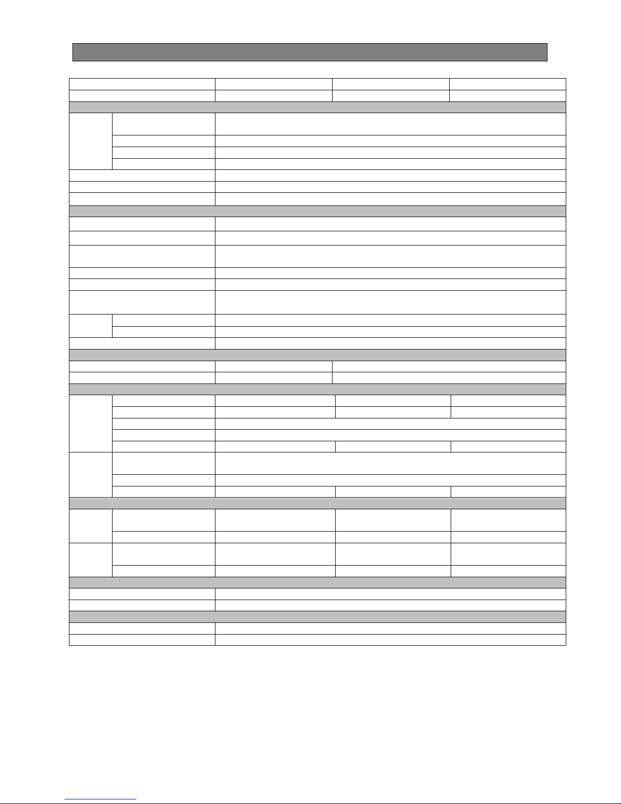
3.2. LCD Panel
Page 12

11
Display
Function
Backup time information
Indicates the remaining backup time in pie chart.
Indicates the remaining backup time in numbers.
H: hours, M: minute, S: second
Fault information
Indicates that the warning and fault occurs.
Indicates the warning and fault codes, and the codes are listed in
details in 3-5 section.
Mute operation
Indicates that the UPS alarm is disabled.
Output & Battery voltage information
Indicates the output voltage, frequency or battery voltage.
Vac: output voltage, Vdc: battery voltage, Hz: frequency
Load information
Indicates the load level by 0-25%, 26-50%, 51-75%, and
76-100%.
Indicates overload.
Indicates the load or the UPS output is short circuit.
Programmable outlets information
Indicates that programmable management outlets are working.
Mode operation information
Indicates the UPS connects to the mains.
Indicates the battery is working.
Indicates the bypass circuit is working.
Indicates the ECO mode is enabled.
Indicates the Inverter circuit is working.
Indicates the output is working.
Battery information
Indicates the Battery level by 0-25%, 26-50%, 51-75%, and
76-100%.
Indicates the battery is fault.
Indicates low battery level and low battery voltage.
Input & Battery voltage information
Indicates the input voltage or frequency or battery voltage.
Vac: Input voltage, Vdc: battery voltage, Hz: input frequency
Page 13

12
3.3. Audible Alarm
Battery Mode
Sounding every 4 seconds
Low Battery
Sounding every second
Overload
Sounding twice every second
Fault
Continuously sounding
Bypass Mode
Sounding every 10 seconds
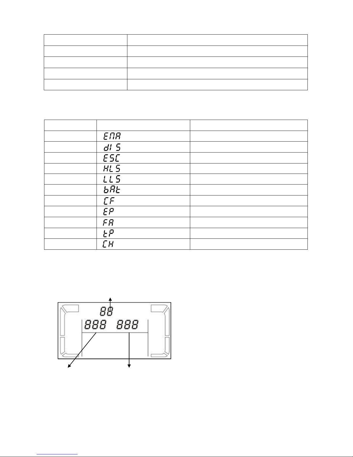
3.4. LCD display wordings index
Abbreviation
Display content
Meaning
ENA
Enable
DIS
Disable
ESC
Escape
HLS
High loss
LLS
Low loss
BAT
Battery
CF Converter
EP EPO
FA Fan
TP Temperature
CH Charger
3.5. UPS Setting
There are three parameters to set up the
UPS.
Parameter 1: It’s for program alternatives.
There are 10 programs to set up. Refer to
below table.
Parameter 2 and parameter 3 are the
setting options or values for each
program.
Parameter 1
Parameter 2
Parameter 3
Page 14

13
01: Output voltage setting
Interface
Setting
Parameter 3: Output voltage
For 200/208/220/230/240 VAC models, you may choose the
following output voltage:
200: present output voltage is 200Vac
208: present output voltage is 208Vac
220: present output voltage is 220Vac
230: present output voltage is 230Vac
240: present output voltage is 240Vac
For 100/110/150/120/127 VAC models, you may choose the
following output voltage:
100: present output voltage is 100Vac
110: present output voltage is 110Vac
115: present output voltage is 115Vac
120: present output voltage is 120Vac
127: present output voltage is 127Vac
02: Frequency Converter enable/disable
Interface
Setting
Parameter 2 & 3: Enable or disable converter mode. You may
choose the following two options:
CF ENA: converter mode enable
CF DIS: converter mode disable
03: Output frequency setting
Interface
Setting
Parameter 2 & 3: Output frequency setting.
You may set the initial frequency on battery mode:
BAT 50: present output frequency is 50Hz
BAT 60: present output frequency is 60Hz
If converter mode is enabled, you may choose the following output
frequency:
CF 50: present output frequency is 50Hz
CF 60: present output frequency is 60Hz
04: ECO enable/disable
Interface
Setting
Parameter 3: Enable or disable ECO function. You may choose
the following two options:
ENA: ECO mode enable
DIS: ECO mode disable
05: ECO voltage range setting
Interface
Setting
Parameter 2 & 3: Set the acceptable high voltage point and low
voltage point for ECO mode by pressing Down key or Up key.
HLS: High loss voltage in ECO mode in parameter 2.
For 200/208/220/230/240 VAC models, the setting range in
parameter 3 is from +7V to +24V of the nominal voltage.
For 100/110/115/120/127 VAC models, the setting range in
parameter 3 is from +3V to +12V of the nominal voltage.
LLS: Low loss voltage in ECO mode in parameter 2.
For 200/208/220/230/240 VAC models, the setting range in
parameter 3 is from -7V to -24V of the nominal voltage.
For 100/110/115/120/127 VAC models, the setting voltage in
parameter 3 is from -3V to -12V of the nominal voltage.
Page 15

14
06: Bypass enable/disable when UPS is off
Interface
Setting
Parameter 3: Enable or disable Bypass function. You may choose
the following two options:
ENA: Bypass enable
DIS: Bypass disable
07: Bypass voltage range setting
Interface
Setting
Parameter 2 & 3: Set the acceptable high voltage point and
acceptable low voltage point for Bypass mode by pressing the
Down key or Up key.
HLS: Bypass high voltage point
For 200/208/220/230/240 VAC models:
230-264: setting the high voltage point in parameter 3 from 230Vac
to 264Vac.
For 100/110/115/120/127 VAC models:
120-132: setting the high voltage point in parameter 3 from 120Vac
to 132Vac
LLS: Bypass low voltage point
For 200/208/220/230/240 VAC models:
170-220: setting the low voltage point in parameter 3 from 170Vac
to 220Vac
For 100/110/115/120/127 VAC models:
85-115: setting the low voltage point in parameter 3 from 85Vac to
115Vac.
08: Programmable outlets enable/disable
Interface
Setting
Parameter 3: Enable or disable programmable outlets.
ENA: Programmable outlets enable
DIS: Programmable outlets disable
09: Programmable outlets setting
Interface
Setting
Parameter 3: Set up backup time limits for programmable outlets.
0-999: setting the backup time limits in minutes from 0-999 for
programmable outlets which connect to non-critical devices on
battery mode.
10: Backup time setting for outlets
Interface
Setting
Parameter 3: Set up backup time on battery mode for general
outlets.
0-999: setting the backup time in minutes from 0-999 for general
outlets on battery mode.
0: When setting as “0”, the backup time will be only 10 seconds.
999: When setting as “999”, the backup time setting will be
disabled.
00: Exit setting
Page 16

15
3.6. Operating Mode Description
Operating mode
Description
LCD display
Online mode
When the input voltage is within
acceptable range, UPS will provide pure
and stable AC power to output. The
UPS will also charge the battery at
online mode.
ECO mode
Energy saving mode:
When the input voltage is within voltage
regulation range, UPS will bypass
voltage to output for energy saving.
Frequency
Converter mode
When input frequency is within 40 Hz to
70 Hz, the UPS can be set at a constant
output frequency, 50 Hz or 60 Hz. The
UPS will still charge battery under this
mode.
Battery mode
When the input voltage is beyond the
acceptable range or power failure and
alarm is sounding every 4 second, UPS
will backup power from battery.
Bypass mode
When input voltage is within acceptable
range but UPS is overload, UPS will
enter bypass mode or bypass mode can
be set by front panel. Alarm is sounding
every 10 second.
Standby mode
UPS is powered off and no output
supply power, but still can charge
batteries.
Page 17

16
3.7. Faults Reference Code
Fault event
Fault code
Icon
Fault event
Fault code
Icon
Bus start fail
01
x
Inverter voltage Low
13
x
Bus over
02
x
Inverter output short
14
Bus under
03
x
Battery voltage too high
27
Bus unbalance
04
x
Battery voltage too low
28
Inverter soft start fail
11
x
Over temperature
41
x
Inverter voltage high
12
x
Over load
43
3.8. Warning indicator
Warning
Icon (flashing)
Alarm
Low Battery
Sounding every second
Overload
Sounding twice every second
Battery is not connected
Sounding every second
Over Charge
Sounding every second
Site wiring fault
Sounding every second
EPO enable
Sounding every second
Fan Failure
Sounding every second
Over temperature
Sounding every second
Charger failure
Sounding every second
Out of bypass voltage range
Sounding every second
Page 18

17
4. Troubleshooting
If the UPS system does not operate correctly, please solve the problem by using the table
below.
Symptom
Possible cause
Remedy
No indication and alarm even
though the mains is normal.
The AC input power is not
connected well.
Check if input power cord
firmly connected to the
mains.
The AC input is connected
to the UPS output.
Plug AC input power cord
to AC input correctly.
The icon and the warning
code flashing on LCD
display and alarm is sounding
every second.
EPO function is activated.
Set the circuit in closed
position to disable EPO
function.
The icon and flashing on
LCD display and alarm is
sounding every second.
Line and neutral
conductors of UPS input
are reversed.
Rotate mains power
socket by 180° and then
connect to UPS system.
The icon and flashing
on LCD display and alarm is
sounding every second.
The external or internal
battery is incorrectly
connected.
Check if all batteries are
connected well.
Fault code is shown as 27 and
the icon is lighting on
LCD display and alarm is
continuously sounding.
Battery voltage is too high
or the charger is fault.
Contact your dealer.
Fault code is shown as 28 and
the icon is lighting on
LCD display and alarm is
continuously sounding.
Battery voltage is too low
or the charger is fault.
Contact your dealer.
The icon and is
flashing on LCD display and
alarm is sounding twice every
second.
UPS is overload
Remove excess loads
from UPS output.
UPS is overloaded.
Devices connected to the
UPS are fed directly by the
electrical network via the
Bypass.
Remove excess loads
from UPS output.
After repetitive overloads,
the UPS is locked in the
Bypass mode. Connected
devices are fed directly by
the mains.
Remove excess loads
from UPS output first.
Then shut down the UPS
and restart it.
Fault code is shown as 43 and
The icon is lighting on
LCD display and alarm is
continuously sounding.
The UPS shut down
automatically because of
overload at the UPS
output.
Remove excess loads
from UPS output and
restart it.
Page 19

18
Symptom
Possible cause
Remedy
Fault code is shown as 14 and
the icon is lighting on
LCD display and alarm is
continuously sounding.
The UPS shut down
automatically because
short circuit occurs on the
UPS output.
Check output wiring and if
connected devices are in
short circuit status.
Fault code is shown as 1, 2, 3, 4,
11, 12, 13 and 41 on LCD display
and alarm is continuously
sounding.
A UPS internal fault has
occurred. There are two
possible results:
1. The load is still
supplied, but directly from
AC power via bypass.
2. The load is no longer
supplied by power.
Contact your dealer
Battery backup time is shorter
than nominal value
Batteries are not fully
charged
Charge the batteries for at
least 5 hours and then
check capacity. If the
problem still persists,
consult your dealer.
Batteries defect
Contact your dealer to
replace the battery.
The icon and the warning
code flashing on LCD
display and alarm is sounding
every second.
Fan is locked or not
working
Check fans and notify
dealer!!
5. Storage and Maintenance
Operation
The UPS system contains no user-serviceable parts. If the battery service life (3~5 years
at 25°C ambient temperature) has been exceeded, the batteries must be replaced. In this
case, please contact your dealer.
Storage
Before storing, charge the UPS 5 hours. Store the UPS covered and upright in a cool, dry
location. During storage, recharge the battery in accordance with the following table:
Storage Temperature
Recharge Frequency
Charging Duration
-25°C - 40°C
Every 3 months
1-2 hours
40°C - 45°C
Every 2 months
1-2 hours
Be sure to deliver the spent battery to a recycling facility or ship it to your
dealer in the replacement battery packing material.
Page 20
19
6. Specifications
MODEL
OL 100 RM
OL 2000 RM
OL 3000 RM
CAPACITY*
1000 VA / 800 W
2000 VA / 1600 W
3000 VA / 2400 W
INPUT
Voltage
Range
Low Line Transfer
80VAC/70VAC/60VAC/50VAC ± 5% or 160VAC/140VAC/120VAC/110VAC ± 5%
( based on load percentage 100% - 80 % / 80 % - 70 % / 70 - 60 % / 60 % - 0)
Low Line Comeback
85VAC/75VAC/65VAC/55VAC ± 5 % or 170VAC/150VAC/130VAC/120VAC± 5 %
High Line Transfer
150 VAC ± 5 % or 300 VAC ± 5 %
High Line Comeback
145 VAC ± 5 % or 290 VAC ± 5 %
Frequency Range
45Hz ~ 55 Hz or 56Hz ~ 65 Hz
Phase
Single phase with ground
Power Factor
≧ 0.99 @ 220-230 VAC or 110-120 VAC
OUTPUT
Output voltage
100/110/115/120/127 VAC or 200/208/220/230/240VAC
AC Voltage Regulation
± 1% (Batt. Mode)
Frequency Range
(Synchronized Range)
48 ~ 52 Hz or 58 ~ 62 Hz
Frequency Range (Batt. Mode)
50 Hz ± 0.2 Hz or 60Hz ± 0.2 Hz
Current Crest Ratio
3:1
Harmonic Distortion
≦ 2% (Linear load)
8% max (Bat mode before shut down)
Transfer
Time
AC Mode to Batt. Mode
Zero
Inverter to Bypass
4 ms (Typical)
Waveform (Batt. Mode)
Pure Sinewave
EFFICIENCY
AC Mode
86 %
88 %
Battery Mode
83 %
85 %
BATTERY
Standard
Model
Battery Type
12 V / 9 AH
12 V / 9 AH
12 V / 9 AH
Numbers 2 4
6
Recharge Time
4 hours recover to 90% capacity (Typical)
Charging Current
1.0 A(max.)
Charging Voltage
27.4 VDC± 1%
54.8VDC ± 1%
82.1VDC ± 1%
Long-run
Model
Battery Type &
Numbers
Depending on the capacity of external batteries
Charging Current
8.0 A(max.)
Charging Voltage
27.4 VDC± 1%
54.8VDC ± 1%
82.1VDC ± 1%
PHYSICAL
Standard
Model
Dimension, D X W X H
mm
380 x 438 x 88
480 x 438 x 88
600 x 438 x 88
Net Weight (kgs)
13.2
20.6
29
Long-run
Model
Dimension, D X W X H
mm
380 x 438 x 88
480 x 438 x 88
600 x 438 x 88
Net Weight (kgs)
9.1
11.3
14.8
ENVIRONMENT
Operation Humidity
20-90 % RH @ 0- 40°C (non-condensing)
Noise Level
Less than 50dBA @ 1 Meter
MANAGEMENT
Smart RS-232 or USB
Supports Windows® 2000/2003/XP/Vista/2008/7, Linux, Unix and MAC
Optional SNMP
Power management from SNMP manager and web browser
* Derate capacity to 60% of capacity in Frequency converter mode and to 80% when the output voltage is adjusted to
208VAC.
Page 21

Источник бесперебойного питания
Powerex OL 1K/2K/3K RM Online UPS Rack
РУКОВОДСТВО ПОЛЬЗОВАТЕЛЯ
RU
Page 22

1
Содержание
1. Важное предупреждение о безопасности…………………………...
2
1.1. Транспортировка
2
1.2. Подготовка
2
1.3. Установка
2
1.4. Эксплуатация
2
1.5. Техническое обслуживание, ремонт и диагностика
3
2. Установка и настройка……………………………………………………
4
2.1. Вид задней панели
4
2.2. Для монтажа в стойку ИБП
4
2.3. Настройка ИБП
5
2.4. Замена батареи
7
2.5. Сборка комплекта батареи (опционально)
8
3. Управление………………………………………………………………….
10
3.1. Управление кнопками
10
3.2. ЖК‐дисплей
10
3.3. Звуковая сигнализация
12
3.4. Индикация на ЖК‐дисплее
12
3.5. Настройка ИБП
12
3.6. Описание рабочего режима
15
3.7. Коды неисправностей
15
3.8. Предупреждающий индикатор
16
4. Диагностика и устранение неисправностей………………………...
17
5. Хранение и техническое обслуживание……………………………..
18
6. Технические характеристики……...……………………………………
19
Page 23

2
1. Важное предупреждение о безопасности
Неукоснительно соблюдайте все предупреждения и инструкции, приведенные в
настоящем руководстве. Храните данное руководство в надежном месте и внимательно
прочтите следующие инструкции перед началом установки. Не приступайте к работе с
устройством, не ознакомившись должным образом с информацией о безопасности и
инструкциями по эксплуатации
1.1. Транспортировка
Транспортируйте ИБП только в оригинальной упаковке (для защиты от ударов и
толчков).
1.2. Подготовка
При перемещении ИБП из холода в тепло может произойти образование
конденсата. При установке ИБП должен быть полностью сухим. Необходимо
подождать не менее двух часов, чтобы ИБП адаптировался к температуре
окружающей среды.
Не устанавливайте ИБП вблизи воды или в условиях повышенной влажности.
Не допускайте воздействия на систему прямого солнечного света или не размещайте
ее рядом с источниками тепла.
Не закрывайте вентиляционные отверстия в корпусе ИБП.
1.3. Установка
Не подключайте оборудование или устройства, которые могут привести к
перегрузке ИБП (например, лазерные принтеры).
Прокладывайте провода таким образом, чтобы никто не мог наступить на них
или споткнуться об них.
Не подключайте к ИБП такие устройства как фены.
ИБП может использоваться любыми лицами и не требует предварительной
подготовки.
Подключайте ИБП только к заземленной ударопрочной розетке, удобно и
близко расположенной к ИБП.
Для подключения ИБП к ударопрочной розетке используйте только провода,
соответствующие требованиям VDE (Общество немецких электриков) и
имеющие маркировку CE (например, провод для подключения питания к
компьютеру).
Для подключения нагрузки к системе ИБП используйте только провода,
соответствующие требованиям VDE (Общество немецких электриков) и
имеющие маркировку CE.
При установке данного оборудования убедитесь в том, что сумма токов утечки
ИБП с подключенным пользовательским оборудованием не превышает 3,5 мА.
1.4. Эксплуатация
Не отключайте во время работы сетевой кабель ИБП или розетку
(ударопрочную), поскольку это может привести к исчезновению защитного
заземления ИБП и всех подключенных к ней нагрузок.
Система ИБП оснащена своим собственным внутренним источником питания
(аккумуляторные батареи). Выходные разъемы ИБП или клеммная колодка
могут находиться под напряжением даже в том случае, если система ИБП не
подключена к розетке.
Чтобы полностью отключить систему ИБП, сначала нажмите кнопку OFF/Enter
для отключения от сети.
Не допускайте попадания жидкостей или посторонних предметов внутрь
корпуса ИБП.
Page 24

3
1.5. Техническое обслуживание, ремонт и диагностика
Система ИБП работает под высоким напряжением. Ремонт должен
выполняться только квалифицированными специалистами.
Осторожно ‐ имеется опасность поражения электрическим током. Даже после
отключения блока от сети электропитания (сетевой розетки помещения)
элементы внутри системы остаются подключенными к аккумулятору, находятся
под напряжением и представляют опасность.
Перед выполнением ремонта и/или технического обслуживания отключите
батареи и убедитесь в том, что система обесточена, и опасное напряжение
отсутствует на выходных контактах конденсаторов (например, конденсаторов
шины).
Замену аккумуляторов и операции осмотра могут производить только
специалисты, знакомые с аккумуляторами, и при условии соблюдения правил
техники безопасности. Людям, не имеющим специального разрешения,
необходимо держаться как можно дальше от аккумуляторов.
Осторожно ‐ имеется опасность поражения электрическим током. Контур
батареи не защищен от входного напряжения. Между контактами и землей
может возникнуть опасное напряжение. Прежде, чем коснуться устройства,
убедитесь в отсутствии высокого напряжения!
Аккумуляторы могут служить причиной удара электрическим напряжением и
обладают сильным током короткого замыкания. Работая с аккумуляторами,
принимайте меры предосторожности, описанные ниже, и прочие необходимые
меры:
Снимайте наручные часы, кольца и прочие металлические предметы
Пользуйтесь только инструментами с изолированными рукоятками.
Заменяйте аккумуляторы изделиями того же типа и в том же количестве.
Не пытайтесь утилизировать аккумуляторы, сжигая их. Это может привести к
взрыву аккумулятора.
Не вскрывайте и не уничтожайте аккумуляторы. Утечка электролита может
вызвать повреждения кожу и глаза. Кроме того, электролит может быть
токсичен.
Во избежание возникновения пожара, заменяйте плавкие предохранители
только на предохранители аналогичного типа с такими же параметрами.
Не разбирайте систему ИБП.
Page 25

4
2. Установка и настройка
ПРИМЕЧАНИЕ: Перед установкой осмотрите устройство. Проверьте комплектность и
убедитесь в том, что никакие элементы не повреждены. Храните упаковку в надежном
месте для повторного использования в будущем.
ПРИМЕЧАНИЕ: Существует два различных типа сетевых ИБП: стандартные и
длительного использования. См. таблицу ниже.
Модель
Тип
Модель
Тип
1K
Стандартный
1K-L
Длительного
использования
2K
2K-L
3K
3K-L
2.1. Вид задней панели
1K(L) & 2K(L)
3K(L)
1. Программируемые выходы: подключение некритической нагрузки.
2. Выходные контакты: подключение критическое нагрузки.
3. Входной переменный ток
4. Автоматический выключатель на входе
5. Защита от перенапряжений для сети/факса/модема
6. Разъем аварийного отключения питания (ЕРО)
7. Коммуникационный порт USB
8. Коммуникационный порт RS‐232
9. Разъем сетевого протокола SNMP
10. Подключение внешней батареи (только для модели L)
2.2. Для монтажа в стойку ИБП
Данный ИБП может быть установлен в 19 "стойки шасси. Пожалуйста, следуйте
приведенным ниже, чтобы установить ИБП.
Шаг 1 Шаг 2
Page 26

5
2.3. Настройка ИБП
Шаг 1: Подключение провода батареи
В целях безопасности ИБП поставляется с отключенными проводами. Перед установкой
ИБП, пожалуйста, следуйте нижеуказанным шагам, чтобы повторно подключить
провода батарей.
Шаг 1
Шаг 2
Шаг 3
Снимите переднюю панель
Подключение входа
переменного тока и вновь
соединить провода
аккумулятора.
Закройте переднюю панель
устройства.
Шаг 2: подключение UPS на входе
Подключайте ИБП только к двухполюсной заземленной розетке с 3 контактами.
Старайтесь не пользоваться удлинителями.
Для моделей 208/220/230/240В перем. тока: Шнур питания поставляется в комплекте
с ИБП
Для моделей 110/115/120/127В перем. тока: Шнур питания поставляется в комплекте
с ИБП. Входной разъем NEMA 5‐15P для моделей 1K и 1K-L, NEMA 5‐20P для
моделей 2K и 2K-L
Примечание: Для низковольтных моделей: Проверьте, не загорается ли индикатор
ошибки подключения на ЖК‐дисплее. Он загорается в случае подключения ИБП к
сетевой розетке с неправильной схемой проводки (см. раздел "Диагностика и
устранение неисправностей").
Шаг 3: подключение UPS на выходе
Существует два типа выходных гнезд: программируемые выходы и общие выходы.
программируемые выходы используются для подключения некритических нагрузок, а
общие выходы ‐ для подключения критических нагрузок. В случае отказа в сети
питания, можно увеличить время резервного питания критических устройств за счет
сокращения времени резервного питания для некритических нагрузок.
Для проводки входных или выходных контактов необходимо выполнить следующие
действия:
a) Снимите крышку клеммной колодки
b) Рекомендуется использовать шнур питания AWG14 или 2,1 мм2.
Рекомендуется использовать шнур питания AWG12‐10 или 3,3 мм2‐5,3 мм2 типа
NEMA.
c) По завершении проводки проверьте надежность соединений.
d) Установите на место крышку задней панели.
Шаг 4: Подключение коммуникаций
Коммуникационный порт:
Порт USB Порт RS-232 Разъем сетевого протокола
Page 27

6
Для автоматического мониторинга включения/выключения и состояния ИБП подключите
один конец коммуникационного кабеля к порту USB/RS‐232, а другой конец ‐ к
коммуникационному разъему на компьютере. С помощью программного обеспечения
для мониторинга, вы можете программировать время включения/выключения ИБП и
осуществлять мониторинг его состояния на ПК.
ИБП оборудован разъемом для сетевой карты SNMP или AS400. Установка карты SNMP
или AS400 в ИБП позволяет воспользоваться расширенными возможностями
коммуникаций и мониторинга.
Примечание: порты USB и RS‐232 не могут использоваться одновременно.
Шаг 5: Сетевое подключение
Порт для подключения функции защиты от перенапряжений сети/факса/модема
Подключите единый провод модема/телефона/факса к выходу “IN” с защитой от
перенапряжений, расположенному на задней панели ИБП. Подключите выходной
разъем “OUT” к оборудованию с помощью другого провода модема/факса/телефона.
Шаг 6: Включение и выключение функции аварийного отключения питания (EPO)
Для нормальной работы ИБП контакты 1 и 2 должны быть соединены между собой.
Чтобы включить функцию аварийного отключения питания, разомкните провод между
контактами 1 и 2.
Шаг 7: Включение ИБП
Для включения ИБП удерживайте нажатой в течение двух секунд кнопку ON/Mute на
передней панели.
Примечание: Батарея достигает полной зарядки в течение первых пяти часов
работы в стандартном режиме. В течение периода зарядки батарея работает не на
полную мощность.
Шаг 8: Установка программного обеспечения
Для оптимальной защиты компьютера установите программное обеспечение ИБП для
мониторинга, чтобы полностью завершить настройку выключения ИБП. Для этого можно
установить прилагаемый компакт‐диск в CD‐ROM для установки программного
обеспечения для мониторинга. В противном случае, выполните следующие шаги для
загрузки и установки программного обеспечения для мониторинга через Интернет:
1. Зайдите на веб‐сайт http://www.power-software-download.com
2. Щелкните значок программного обеспечения ViewPower и выберите свою ОС для
загрузки программного обеспечения.
3. Следуйте инструкциям на экране для установки программного обеспечения.
4. После перезагрузки компьютера в системной области возле часов появится
оранжевый значок программного обеспечения для мониторинга.
Для работы ИБП в обычном
режиме эти контакты должны быть
соединены
Page 28

7
Шаг 9: Подключение внешней батареи (только для моделей длительного использования)
Для подключения внешней батареи см. таблицу ниже.
2.4. Замена батареи
ВНИМАНИЕ: Данный ИБП оснащен внутренней батареей и пользователь может
заменить батареи без отключения ИБП или подключенных нагрузок (горячей замены
батарей). Замена является безопасной процедурой, без опасности поражения
электрическим током.
ВНИМАНИЕ! Пожалуйста, соблюдайте все предупреждения, предостережения и
примечания перед заменой батарей.
Примечание: Если батарея отсоединена, оборудование не защищено от перебоев в
подаче электроэнергии.
Шаг 1
Шаг 2
Шаг 3
Снимите переднюю панель
Отсоедините провода
батареи.
Вытащите аккумуляторный блок,
удалив два винта на передней
панели
Шаг 4
Шаг 5
Шаг 7
Снимите верхнюю крышку
батарейного блока и
замените батареи внутри
После замены батареи верните
батарейный блок в
первоначальное положение и
Подключите провода батареи
Page 29

8
закрепите его крепко.
Шаг 8
Закройте переднюю панель устройства
2.5. Аккумулятор монтажный комплект (опционально)
ПРИМЕЧАНИЕ: Пожалуйста, соберите комплект батареи перед установкой его внутри
ИБП. Пожалуйста, выберите соответствующую процедуру установки.
комплект из 2 батарей
Шаг 1: Удалите клейкие ленты
Шаг 2: Соедините все клеммы батареи в
соответствии со следующей схемой
Шаг 3: Поместите собранный комплект
батареи на одной стороне пластиковой
оболочки
Шаг 4:Закройте другую сторону пластиковой
оболочки согласно укажанной ниже схеме.
Теперь комплект батареи собран правильно
клейкие ленты
Page 30

9
Комплект из 4 батарей
Шаг 1: Удалите клейкие ленты.
Шаг 2: Соедините все клеммы батареи согласно
ниже указанной схеме
Шаг 3: Поместите собранный комплект
батареи на одной стороне пластиковой
оболочки
Шаг 4: Закройте другую сторону пластиковой
оболочки как показано ниже на диаграмме.
Теперь комплект батареи аккумулятор собран
правильно
Комплект из 6 батарей
Шаг 1: Удалите клейкие ленты
Шаг 2: Соедините все клеммы батареи, в
соответствии со следующей диаграммой
Шаг 3: Поместите собранный комплект
батареи на одной стороне пластиковой
оболочки
Шаг 4: Закройте другую сторону пластиковой
оболочки, как показано ниже на диаграмме.
Теперь комплект батареи собран правильно
клейкие
ленты
клейкие ленты
клейкие ленты
клейкие
ленты
Page 31

10
Page 32

11
3. Управление
3.1. Управление кнопками
Кнопка
Функция
Кнопка ON/Mute
Включение ИБП: Чтобы включить ИБП, удерживайте нажатой
кнопку ON/Mute в течение 2 секунд.
Выключение сигнализации: Когда ИБП работает от батареи,
удерживайте нажатой эту кнопку в течение 5 секунд для
включения/выключения сигнализации. Это не применимо для
ситуаций, когда появляются ошибки или предупреждения..
Кнопка перемещения вниз: Нажмите эту кнопку для просмотра
предыдущих выбранных элементов в режиме настройки ИБП.
Переключение ИБП в режим самотестирования: Находясь в
режиме питания переменного тока, в экономичном режиме или в
режиме преобразователя, нажимайте одновременно кнопки
ON/Mute в течение 5 секунд для перехода в режим
самотестирования ИБП.
Кнопка OFF/Enter
Выключение ИБП: Удерживайте нажатой эту кнопку в течение 2
секунд для выключения ИБП в режиме работы от батареи. ИБП
будет работать в ждущем режиме при стандартном питании или
перейдет в режим шунтирования, если включена функция
шунтирования.
Кнопка подтверждения: Нажмите эту кнопку для подтверждения
выбора в режиме настройки ИБП.
Кнопка Select
Переключение сообщения на ЖК‐дисплее: Нажмите эту кнопку,
чтобы изменить сообщение на ЖК‐дисплее на данные входного
напряжения, входной частоты, напряжения батареи, выходного
напряжения и выходной частоты. После 10 ‐ секундной паузы
экран дисплей вернется в состояние по умолчанию.
Режим настройки: Удерживайте нажатой эту кнопку в течение 5
секунд для перехода в режим настройки ИБП, в то время, пока ИБП
находится в ждущем режиме или в режиме шунтирования
Кнопка перемещения вверх: Нажмите эту кнопку для просмотра
следующих выбранных элементов в режиме настройки ИБП
Кнопка ON/Mute
+ кнопка Select
Переключение в режим шунтирования: В обычном режиме питания
от сети нажимайте кнопки ON/Mute и Select одновременно в
течение 5 секунд. ИБП перейдет в режим шунтирования. Эти
действия не будут иметь результата, если входное напряжение
находится за пределами допустимого диапазона.
3.2. ЖК‐дисплей
Page 33

12
Дисплей
Функция
Информация о времени резервного питания
Показывает время резервного питания в виде круговой диаграммы
Показывает время резервного питания в цифрах
H: часы, M: минуты, S: секунды
Информация об ошибках
Показывает предупреждения и информацию об ошибках
I Показывает предупреждения и коды ошибок; подробные описания
кодов приводятся в разделе 3‐5
Отключение звука
Показывает, что сигнализация ИБП отключена
Информация о выходном напряжении и напряжении батареи
Показывает выходное напряжение, частоту или напряжение батареи
В перем. тока: выходное напряжение, В пост. тока: напряжение батареи,
Гц: частота
Информация о нагрузке
Показывает уровень нагрузки: 0‐25%, 26‐50%, 51‐75% и 76‐100%
Указывает на перегрузку
Указывает на перегрузку или на короткое замыкание на выходе ИБП
Информация о программируемых выходах
Указывает на работу программируемых выходов
Информация о режиме работы
Указывает на подключение ИБП к сети питания
Указывает на работу от батареи
Указывает на работу обходного контура
Указывает на работу в экономичном режиме
Указывает на работу контура инвертора
Указывает на работу выхода
Информация о батарее
Показывает уровень заряда батареи: 0‐25%, 26‐50%, 51‐75% и
76‐100%
Указывает на неисправность батареи
Указывает на низкий уровень заряда и низкую мощность батареи
Информация о входном напряжении и напряжении батареи
Показывает входное напряжение, частоту или напряжение батареи
В перем. тока: входное напряжение, В пост. тока: напряжение батареи, Гц:
частота на входе
Page 34
13
3.3. Звуковая сигнализация
Режим работы от батареи
Сигнал подается каждые 4 секунды
Низкий заряд батареи
Сигнал подается каждую секунду
Перегрузка
Сигнал подается дважды каждую секунду
Отказ
Сигнал звучит постоянно
Режим шунтирования
Сигнал подается каждые 10 секунды
3.4. Индикация на ЖК‐дисплее
Сокращение
Индикация на дисплее
Значение
ENA
Включить
DIS
Отключить
ESC
Выход
HLS
Высокий уровень потери
LLS
Низкий уровень потери
BAT
Батарея
CF Конвертер
EP EPO
FA Вентилятор
TP Температура
CH Зарядное устройство
3.5. Настройка ИБП
Существует три параметра настройки
ИБП.
Параметр 1: для альтернативных
программ. Существует 10 программ
настройки. См. таблицу ниже.
Параметры 2 и 3 ‐ это параметры
настройки или значения для каждой
программы.
Параметр 1
Параметр 2
Параметр 3
Page 35

14
01: Настройка выходного напряжения
Интерфейс
Настройка
Параметр 3: Выходное напряжение
Для моделей 200/208/220/230/240 В переменного тока
можно выбрать следующее значение выходного
напряжения:
200: выходное напряжение составляет 200 В переменного тока
208: выходное напряжение составляет 208 В переменного тока
220: выходное напряжение составляет 220 В переменного тока
230: выходное напряжение составляет 230 В переменного тока
240: выходное напряжение составляет 240 В переменного тока
Для моделей 100/110/150/120/127 В переменного тока
можно выбрать следующее значение выходного
напряжения:
100: выходное напряжение составляет 100 В переменного тока
110: выходное напряжение составляет 110 В переменного тока
115: выходное напряжение составляет 115 В переменного тока
120: выходное напряжение составляет 120 В переменного тока
127: выходное напряжение составляет 127 В переменного тока
02: Включение/выключение частотного преобразователя
Интерфейс
Настройка
Параметры 2 и 3: Включение или выключение режима
преобразователя. Можно выбрать один из следующих двух
вариантов:
CF ENA: режим преобразователя включен
CF DIS: режим преобразователя выключен
03: Настройка выходной частоты
Интерфейс
Настройка
Параметры 2 и 3: Настройка выходной частоты.
Настройка исходной частоты в режиме работы от батареи:
BAT 50: выходная частота составляет 50 Гц
BAT 60: выходная частота составляет 60 Гц
При включенном режиме преобразователя можно выбрать
следующие значения выходной частоты:
CF 50: выходная частота составляет 50 Гц
CF 60: выходная частота составляет 60 Гц
04: Включение/выключение экономичного режима
Интерфейс
Настройка
Параметр 3: Включение или выключение функции
экономичного режима. Можно выбрать один из следующих
двух вариантов:
ENA: Включение экономичного режима
DIS: Экономичный режим отключен
05: Настройка диапазона напряжения в экономичном режиме
Интерфейс
Настройка
Параметры 2 и 3: Для настройки точки максимально высокого
напряжения и низкого напряжения в экономичном режиме
воспользуйтесь кнопками перемещения вверх и вниз.
HLS: Напряжение при высоких потерях в экономичном режиме
для параметра 2.
Для моделей 200/208/220/230/240 В переменного тока диапазон
настройки параметра 3 составляет от +7 В до +24 В номинального
напряжения.
Для моделей 100/110/115/120/127 В переменного тока диапазон
настройки параметра 3 составляет от +3 В до +12 В номинального
Page 36

15
напряжения.
LLS: Напряжение при низких потерях в экономичном режиме для
параметра 2.
Для моделей 200/208/220/230/240 В переменного тока диапазон
настройки параметра 3 составляет от ‐7 В до ‐24 В номинального
напряжения.
Для моделей 100/110/115/120/127 В переменного тока диапазон
настройки параметра 3 составляет от ‐3 В до ‐12 В номинального
напряжения.
06: Включение/выключение режима шунтирования при выключенном ИБП
Интерфейс
Настройка
Параметр 3: Включение или выключение функции
шунтирования. Можно выбрать один из следующих двух
вариантов:
ENA: Функция шунтирования включена
DIS: Функция шунтирования выключена
07: Настройка диапазона напряжения в режиме шунтирования
Интерфейс
Настройка
Параметры 2 и 3: Для настройки точки максимально
высокого напряжения и низкого напряжения в режиме
шунтирования воспользуйтесь кнопками перемещения
вверх и вниз.
HLS: Точка максимального напряжения в режиме
шунтирования
Для моделей 200/208/220/230/240 В перем. тока:
230‐264: настройка точки максимального напряжения для
параметра 3 ‐ от 230 В до 264 В перем. тока
Для моделей 100/110/115/120/127 В перем. тока:
120‐132: настройка точки максимального напряжения для
параметра 3 ‐ от 120 В до 132 В перем. тока
LLS: Точка минимального напряжения в режиме
шунтирования
Для моделей 200/208/220/230/240 В перем. тока:
170‐220: настройка точки минимального напряжения для
параметра 3 ‐ от 170 В до 220 В перем. тока
Для моделей 100/110/115/120/127 В перем. тока:
85‐115: настройка точки минимального напряжения для
параметра 3 ‐ от 85 В до 115 В перем. тока.
08: Включение/выключение программируемых выходов
Интерфейс
Настройка
Параметр 3: Включение или выключение
программируемых выходов.
ENA: Программируемые выходы включены
DIS: Программируемые выходы выключены
09: Настройка программируемых выходов
Интерфейс
Настройка
Параметр 3: настройка предельных значений времени
резервного питания для программируемых выходов.
0‐999: настройка предельных значений времени
резервного питания в минутах от 0 до 999 для
программируемых выходов, используемых для
подключения некритических устройств в режиме работы от
батареи.
Page 37

16
10: Настройка общих выходов (критические нагрузки)
Интерфейс
Настройка
Параметр 3: настройка предельных значений времени
резервного питания для общих выходов.
0‐999: настройка предельных значений времени
резервного питания в минутах от 0 до 999 для общих
выходов, используемых для подключения критических
устройств в режиме работы от батареи.
0: Если значение равно "0", резервное время будет только
10 секунд.
999: Если значение равно "999", Настройка в резервное
время отключена
00: Выйдите из настроек
3.6. Описание рабочего режима
Рабочий режим
Описание
ЖК‐дисплей
Сетевой режим
Когда входное напряжение находится в
пределах допустимого диапазона, ИБП
обеспечивает ровное и стабильное питание
переменного тока на выходе. Кроме того, в
режиме работы ИБП от сети осуществляется
зарядка батареи.
Экономичный
режим
Энергосберегающий режим:
Когда входное напряжение находится в
стабильных пределах, ИБП осуществляет
шунтирование в целях энергосбережения.
Режим
преобразователя частот
Когда входные частоты находятся в
диапазоне 40‐70 Гц, для ИБП может быть
установлена постоянная выходная частота
50‐60 Гц. При этом ИБП все равно будет
получать питание от батареи.
Режим работы от
батареи
Если входные частоты выходят за пределы
допустимого диапазона или если происходит
сбой питания либо сигнализация
срабатывает каждые 4 секунды, ИБП
переходит в режим резервного питания от
батареи.
Режим
шунтирования
Если входное напряжение находится в
пределах допустимого диапазона, но
имеется перегрузка, ИБП переходит в режим
шунтирования либо режим шунтирования
можно настроить на передней панели.
Звуковая сигнализация срабатывает каждые
10 секунд.
Ждущий режим
ИБП выключен, и питание от него не
поступает, но при этом батарея продолжает
заряжаться.
Page 38

17
3.7. Коды неисправностей
Неисправность
Код
Значок
Неисправность
Код
Значок
Сбой запуска шины
01
x
Низкий уровень напряжения
инвертора
13
x
Перегрузка шины
02
x
Недостаточное выходное
напряжение инвертора
14 Недостаточная нагрузка шины
03
x
Слишком высокое напряжение
батареи
27 Дисбаланс шины
04
x
Слишком низкое напряжение
батареи
28
Сбой плавного запуска шины
11 x Превышение температуры.
41
x
Высокое напряжение
инвертора
12
x
Перегрузка
43
3.8. Предупреждающий индикатор
Предупреждение
Значок (мигающий)
Сигнализация
Низкий заряд батареи
Сигнал подается каждую секунду
Перегрузка
Сигнал подается дважды каждую
секунду
Батарея не подключена
Сигнал подается каждую секунду
Избыточная зарядка
Сигнал подается каждую секунду
Ошибка проводки на месте
установки
Сигнал подается каждую секунду
Включена функция
аварийного отключения
питания (EPO)
Сигнал подается каждую секунду
Сбой вентилятора
Сигнал подается каждую секунду
Превышение температуры
Сигнал подается каждую секунду
Сбой зарядного устройства
Сигнал подается каждую секунду
Превышение диапазона
напряжения в режиме
шунтирования
Сигнал подается каждую секунду
Page 39

18
4. Диагностика и устранение неисправностей
В случае неправильной работы системы ИБП воспользуйтесь приведенной ниже
таблицей для диагностики и устранения неисправности.
Проявление
Возможная причина
Решение
Отсутствует индикация и
срабатывает сигнализация,
несмотря на то, что питание от
сети подается нормально.
Неправильно одключено
питание переменного тока.
Проверьте надежность
подключения шнура
питания к розетке.
питание переменного тока
подается на выходной
разъем ИБП.
Правильно подключите
шнур питания источнику
питания переменного тока.
На ЖК‐дисплее мигает
значок и код ошибки
, игнализация срабатывает
каждую секунду.
включена функция
аварийного отключения
(ЕРО).
Для выключения ункции
аварийного отключения
(ЕРО) установите контур в
замкнутое положение.
На ЖК‐дисплее мигает значок
и индикация ,
сигнализация срабатывает
каждую секунду.
Линейные и нулевые
провода на входе ИБП
подключены наоборот.
Переверните сетевую
розетку на 180°, а затем
подключите ИБП.
На ЖК‐дисплее мигает значок
и индикация ,
сигнализация срабатывает
каждую секунду.
Неправильно подключена
внешняя или внутренняя
батарея.
Проверьте правильность
подключения батареи.
Появляется код ошибки 27 и на
ЖК‐дисплее загорается значок
, непрерывно звучит
сигнализация.
Слишком высокое
напряжение батареи или
зарядное устройство
неисправно.
Обратитесь к поставщику.
Появляется код ошибки 28 и на
ЖК‐дисплее загорается значок
, непрерывно звучит
сигнализация.
Слишком низкое
напряжение батареи или
зарядное устройство
неисправно.
Обратитесь к поставщику.
На ЖК‐дисплее мигает значок
и индикация ,
сигнализация срабатывает
каждую секунду.
Перегрузка ИБП
Удалите избыточную
нагрузку на выходе ИБП.
Перегрузка ИБП.
Устройства, подключенные
к ИБП, получают питание
непосредственно от
электрической сети через
шунтирование.
Удалите избыточную
нагрузку на выходе ИБП.
После нескольких
перегрузок ИБП
блокируется в режиме
шунтирования.
Подключенные устройства
получают питание
непосредственно от сети.
Сначала удалите
избыточную нагрузку на
выходе ИБП. Затем
выключите и перезагрузите
ИБП.
Появляется код ошибки 43 и на
ЖК‐дисплее загорается значок
, непрерывно звучит
сигнализация.
ИБП выключается
автоматически в
результате перегрузки на
выходе.
Удалите избыточную
нагрузку на выходе ИБП и
перезагрузите его.
Page 40

19
Проявление
Возможная причина
Решение
Появляется код ошибки 14 и на
ЖК‐дисплее загорается значок
, непрерывно звучит
сигнализация.
ИБП выключается
автоматически в
результате короткого
замыкания на выходе.
Проверьте проводку на
выходе и наличие короткого
замыкания подключенных
устройств.
На ЖК‐дисплее появляется код
ошибки 1, 2, 3, 4, 11, 12, 13 и 41,
непрерывно звучит сигнализация.
Внутренний сбой ИБП. Это
может привести к двум
возможным результатам:
1. Нагрузка будет
продолжать получать
питание, но
непосредственно от сети
через шунтирование.
2. Питание перестанет
подаваться на
подключенные устройства.
Обратитесь к поставщику.
Время резервного питания от
батареи меньше номинального
значения
Батареи заряжены не
полностью.
Зарядите батареи в
течение 5 часов, а затем
проверьте их емкость. Если
неисправность
сохраняется, обратитесь к
поставщику.
Батареи неисправны
Обратитесь к поставщику
или замените батареи.
На ЖК‐дисплее мигает значок
и код ошибки ,
сигнализация срабатывает
каждую секунду.
Вентилятор заблокирован
или неисправен
Проверьте состояние
вентиляторов и сообщите
об этом поставщику!
5. Хранение и техническое обслуживание
Эксплуатация
ИБП не содержит частей, обслуживаемых пользователем. По окончании срока службы
(3~5 лет при температуре 25°C) батареи необходимо заменить. Обратитесь к
поставщику.
Хранение
Перед постановкой на хранение зарядите ИБП в течение 5 часов. Храните ИБП в
вертикально в накрытом виде, в сухом и прохладном месте. Во время хранения
заряжайте батарею в соответствии со следующей таблицей:
Температура хранения
Частота зарядки
Продолжительность
зарядки
-25°C - 40°C
Раз в 3 месяца
1 ‐2 часа
40°C - 45°C
Раз в 2 месяца
1 ‐2 часа
Сдавайте отработавшую батарею в пункт утилизации или отправьте
поставщику в упаковке от новой батареи.
Page 41

20
6. Технические характеристики
МОДЕЛЬ
OL 1000 RM
OL 2000 RM
OL 3000 RM
Мощность*
1000 ВА / 800 Вт
2000 ВА / 1600 Вт
3000 ВА / 2400 Вт
ВХОДНЫЕ ХАРАКТЕРИСТИКИ
Диапазон
Допустимых
значений
напряжения
Передача низкого
напряжения
80 В перем. тока / 70 В перем. тока / 60 В перем. тока / 50 В перем. тока ± 5 % or 160 В
перем. тока / 140 В перем. тока / 120 В перем. тока / 110 В перем. тока ± 5 %
(на основе нагрузки в процентах: 100% ‐ 80 % / 80 % ‐ 70 % / 70 ‐ 60 % / 60 % ‐ 0)
Возврат низкого
напряжения
85 В перем. тока / 77 В перем. тока / 65 В перем. тока / 55 В перем. тока ± 5 % or 170 В
перем. тока / 150 В перем. тока / 130 В перем. тока / 120 В перем. тока ± 5 %
Передача высокого
напряжения
150 В перем. тока ± 5 % или 300 В перем. тока ± 5 %
Возврат высокого
напряжения
145 В перем. тока ± 5 % или 290 В перем. тока ± 5 %
Частотный диапазон
45 Гц ~ 55 Гц или 56 Гц ~ 65 Гц
Фаза
Одна фаза с заземлением
Коэффициент полезного действия
≧0,99 при 200‐230 В перем. тока или 100‐120 В перем. тока
ВЫХОДНЫЕ ХАРАКТЕРИСТИКИ
Выходное напряжение
200/208/220/230/240 В перем. тока или 100/110/115/120/127 В перем. тока
Регулировка напряжения напряжения
перем. тока
± 1% (режим работы от батареи)
Частотный диапазон
(синхронизированный диапазон)
48 ~ 52 Гц или 58 ~ 62 Гц
Частотный диапазон (режим работы
от батареи)
50 Гц ± 0,2 Гц или 60 Гц ± 0,2 Гц
Текущий коэффициент пиковой
импульсной нагрузки
3:1
Гармонические искажения
≦ 2 % полный коэффициент гармоник (линейная нагрузка)
8 % (макс.) (Режиме работы от батарей, прежде чем закрыть )
Время
перехода
из режима питания
переменного тока в режим
работы от батареи
Ноль
Из режима инвертера в
Режим унтирования
4 мс (станд.)
Колебания (в режиме работы от
батареи)
Чистая синусоида
ЭФФЕКТИВНОСТЬ
Режим питания от сети переменного
тока
85%
88%
Режим работы от батареи
83%
85%
АККУМУЛЯТОР
Стандартна
я модель
Тип батареи
12 В / 9 Ач
12 В / 9 Ач
12 В / 9 Ач
Число
2 4 6
Время зарядки
восстановление до 90% за 4 часа (станд.)
Ток зарядки
1,0 A (макс.)
Напряжение зарядки
27,4 В пост. тока ± 1%
41,0 В пост. тока ± 1%
82,1 В пост. тока ± 1%
Модель для
длительного
использован
ия
Тип и число батарей
В зависимости от емкости внешних батарей
Ток зарядки
8,0 A (макс.)
Напряжение зарядки
27,4 В пост. тока ± 1%
41,0 В пост. тока ± 1%
82,1 В пост. тока ± 1%
ФИЗИЧЕСКИЕ ХАРАКТЕРИСТИКИ
Корпус типа
"башня"
Габаритные размеры,
ГxШxВ (мм)
380 x 438 x 88
480 x 438 x 88
600 x 438 x 88
Вес нетто (кг)
13.2
20.6
29
Корпус для
установки в
стойку
Габаритные размеры,
ГxШxВ (мм)
380 x 438 x 88
480 x 438 x 88
600 x 438 x 88
Вес нетто (кг)
9.1
11.3
14.8
ВНЕШНИЕ УСЛОВИЯ
Влажность
20‐90 % рт. ст. при температуре 0‐ 40°C (без образования конденсата)
Уровень шума
Менее 50 дБА на 1 метр
УПРАВЛЕНИЕ
Сетевой разъем RS‐232 или USB
Поддержка Windows® 2000/2003/XP/Vista/2008/ 7, Linux, Unix и MAC
Дополнительный протокол SNMP
Управление мощностью с помощью сетевого клиента SNMP и веб‐браузера
* Способность понижения номинальных значений до 60% в режиме частотного преобразователя и 80% при регулировке
выходного напряжения до 200/208 В перем. тока.
 Loading...