

Page 1
Application
µ
Nà
àTES:
àà
Product Information:
M57182N-315 and M57184N-715
Hybrid DC-DC Converters
By Eric Motto and Joanne Achhammer
Second Release – June 20, 2000
(1) Introduction
The M57182N-315 and M57184N-715 are high input voltage, non-isolated, step down, DC-DC
converters designed to provide low voltage control power for Application Specific Intelligent Power Modules
(ASIPM), Original DIP-IPMs, Mini DIP-IPMs and hybrid gate drivers. These converters accept input voltages of
140VDC to 380VDC allowing them to operate directly from rectified AC line voltages of 100VAC to 240VAC. The
M57182N-315 provides a 200mA regulated 15V DC output. The M57184N-715 supplies a 350mA, 15 VDC
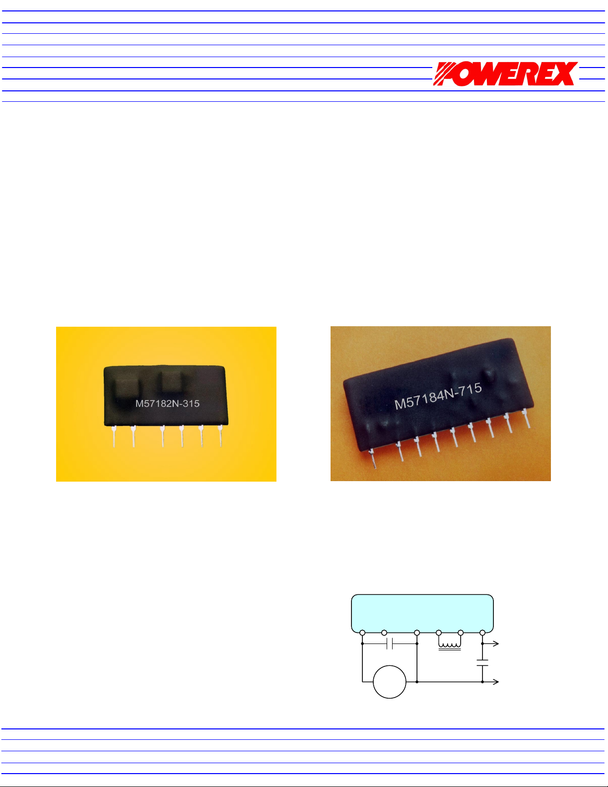
output and a 200mA, 5V DC output. Photographs of the M57182N-315 and M57184N-715 are shown in Figure
1. Each circuit is configured in a compact SIP (Single In-line Package) to allow efficient layout with minimum
printed circuit board space.
(2) Basic Circuit for the M57182N-315
required to complete the circuit. A 10µF 450V low impedance type electrolytic capacitor is connected between
pins 1 and 6 to provide decoupling for the input voltage. For
effective high frequency decoupling the capacitor should be
located as close as possible to the hybrid circuit and connected
with short traces. The output voltage is filtered by connecting a
220µF 50V low impedance electrolytic from pin 12 to common.
Like the input decoupling capacitor, this capacitor should also
be connected with short traces to the hybrid circuit. A 1mH,
500mA inductor connected between pins 8 and 10 completes
the circuit. The selection and characteristics of this inductor will
be discussed in detail in Section (4). Pin 3 of the M57182N-315
is used for factory testing purposes. Do not connect any
external circuits to this pin.
Figure 1a: M57182N-315
Figure 2 shows the basic application circuit for M57182N-315. Only three external components are
Figure 2: M57182N-315 Basic Circuit
Figure 1b: M57184N-715
M57182N-315
1 3 6 8 10 12
10
+
140-400
+
F 450V
VDC
1mH
+
220µF
50V
VO
(+15V, 200mA)
Common
Page 2
(3) Basic Circuit for the M57184N-715
r
µ
(
)
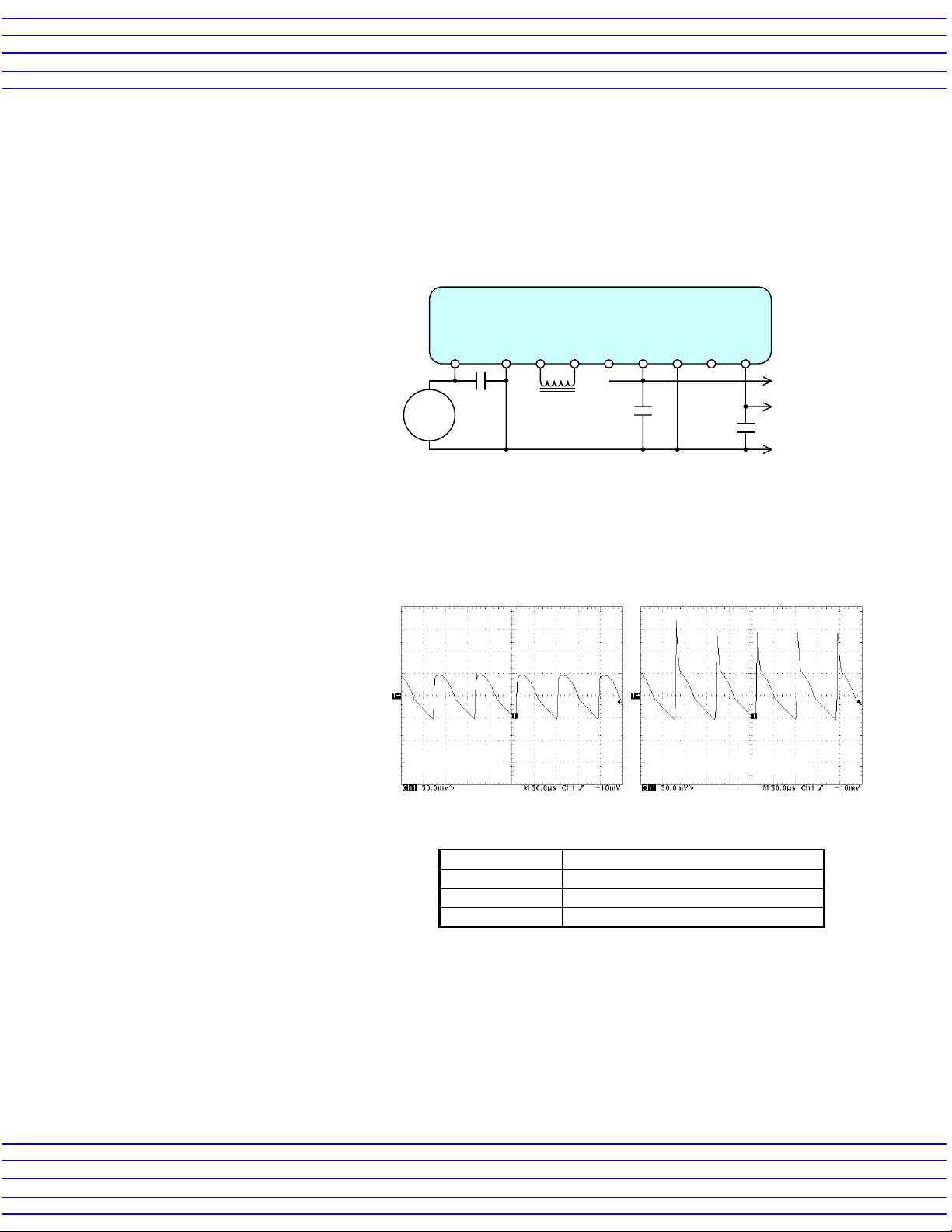
Figure 3 shows the basic application circuit for M57184N-715. Only four external components are
required to complete the circuit. A 10µF 450V low impedance type electrolytic capacitor is connected between
pins 1 and 4 to provide decoupling for the input voltage. For effective high frequency decoupling this capacitor
should be located as close as possible to the hybrid circuit and connected with short traces. The output voltages
are filtered by connecting a 220µF 50V low
impedance electrolytic from pin 10 to
common and a 100µF 50V low impedance
Figure 3: M57184N-715 Basic Circuit
electrolytic from pin 18 to common. The
+15V output on pin 10 is connected to the
input of the +5V regulator at pin 12. Like
the input decoupling capacitor, these
capacitors should also be connected with
short traces to the hybrid circuit. A 1mH,
500mA inductor connected between pins 6
and 8 completes the circuit. The selection
and characteristics of this inductor will be
discussed in detail in Section (4). Pin 16 of
1 4 6 8 10 12 14 16 18
+
+
10
140-400
VDC
F
450V
M57184N-715
1mH
220µF
50V
+
100µF
50V
+
VO-1
+15V, 350mA
-2
V
O
(+5V, 200mA)
Common
the M57184N-715 is used for factory
testing purposes. Do not connect any
external circuits to this pin.
(4) Inductor Selection for the M57184N-715 and M57184N-715
The 1mH inductor should be
50mV/div (AC-Coupled), 50µs/div
rated for at least 500mA and be free of
saturation with superimposed DC.
Undesirable saturation of the inductor
can be detected by monitoring the ripple
voltage across the filter capacitor on the
+15V output. Figure 4 shows an AC
coupled oscilloscope waveforms of the
output ripple voltage with acceptable
and unacceptable inductors. This
measurement should be made using the
Good Inducto
Saturating Inductor
maximum input voltage expected in the
application and the +15V output fully
loaded. For the M57184N-715 the +5V
Figure 4: Output Ripple Voltage Waveforms
output should be unloaded while
measuring the ripple voltage on the
+15V output. Table 1 lists some acceptable
inductors.
Manufacturer Part Number
Mitsumi C13-FR Series, Type #GA 102
API Delevan 4590-105K
J.W. Miller 5900-102
Table 1: Example Inductors
Caution - electrical shock hazard: The M57182N-315 and M57184N-715 are non-isolated DC-DC converters.
Even though the output voltage is low (15V and 5V) their common ground potentials are directly tied to the high
voltage DC input supply. All circuits connected to the output of the M57182N-315 and M57184N-715 must be
treated as high voltage.
Page 3

(5) Application Examples
µ
The M57182N-315 and
M57184N-715 are general-purpose
high input voltage step down
converters. They are useful for variety
of applications where low voltage
control power must be derived from
rectified AC line voltages. The
examples presented in this section
show a few possible uses for these
DC-DC converters.
A. Control Power for DIP-IPMs
The M57184N-715 is ideal for
use with Powerex DIP-IPMs. These
intelligent power modules are
designed to use bootstrap techniques
to develop the required floating
supplies for the high side gate drive
from a single 15VDC supply
referenced to the negative side of the
main DC bus. The DIP-IPMs also
require a 5VDC supply for pull-up of
the logic level control inputs. Figure 5
shows an example application circuit
using the M57184N-715 to provide
both control and logic power for a
DIP-IPM. As shown in figure 5 the
required power supplies are derived
directly from the main DC link voltage
(V
).
CC
B. Power for Hybrid IGBT Gate
drivers.
The M57182N-315 can be
used to derive power for IGBT gate
drive circuits directly from the high
voltage DC link. Figure 6 shows a
complete self-powered IGBT gate
driver with short circuit protection.
The control input signal and fault
feedback are opto-isolated
allowing direct connection to
control logic. In Figure 6 an IGBT
module and a free-wheeling diode
configured as a DC chopper. The
M57182N-315 converts the main
DC bus voltage to 15V that is then
fed to an M57145L-01 to create an
isolated +15V/-8V supply for the
Fault
Control
On/Off
hybrid IGBT gate driver. The
isolation eliminates problems with
ground loop noise.
Controller
Com.
Figure 5: Power Supply for DIP IPM
V
UFS
V
UFB
V
P1
+V
5V
15V
U
V
VFS
V
VFB
V
V
V
WFS
V
WFB
V
W
U
V
W
F
V
V
P
P1
P
P1
P
N
N
N
O
N1
NC
100µF
+
CC
HVIC
+V
CC
HVIC
+V
CC
HVIC
Input Signal
Conditioning
Fault
Logic
+V
CC
UV
Prot.
LVIC
50V
UV Prot.
Level Shift
C
IN
Level Shift
Level Shift
Over-Current
Protection
220µF
50V
+
Gate Drive
UV Prot.
Gate Drive
UV Prot.
Gate Drive
Gate Drive
1mH
Input
Condition
Input
Condition
Input
Condition
M57184N-715
Figure 6: Power Supply for IGBT Gate Driver
M57145L-01
13 1181092
15V
220µF
+
+
+
50V
113 9 810 214 6 5734
M57160AL-01
U
V
Motor
W
P
+
N
10
F
450V
+
14 6 8 1012141618
M57182N-315
1mH
RTC
10µF 450V
LOAD
V
+
140-400
VDC
CC
136 8 10 12
Page 4

C. Control Power
U
U
V
R
r
µ
for ASIPM
Powerex
ASIPMs have
integrated bootstrap
circuits to provide
floating power for the
high side gate
drivers. These
modules are
220µF
50V
designed to use a
single 15V control
power supply to
power all of the built
in gate drive and
protection circuits.
The M57182N-315
provides a simple
low cost means for
generating the
required power
directly from the
main DC bus
Controller
voltage. Figure 7
shows a typical
application circuit for
a Powerex version 3
ASIPM (PS1103X
series) using the
M57182N-315 for
control power.
15V
Figure 7: Control Power Supply for Version 3 ASIPM
M57182N-315
1mH
+
V
D
UP
VP
WP
UN
VN
WN
Fo
V
amp
TH
GND
V
Input signal conditioning
Fault
Logic
CC
(Shoot-Through Interlock)
10
HVASIC
Level
Shift
Level
Shift
Level
Shift
OC/SC
Detect
+
F 450V
Gate Drive
UV Lock-Out
Gate Drive
UV Lock-Out
Gate Drive
UV Lock-Out
Gate Drive
UV Lock-Out
136810 12
+
-
+
-
+
C
C
C
B
B
BV
C
BV
BW
-
C
C
BW
P2
U
Motor
W
Inrush
Limite
P1
S
T
N1
N2
230
VAC
 Loading...