

Page 1
500 Amperes / Up to 1800 Volts
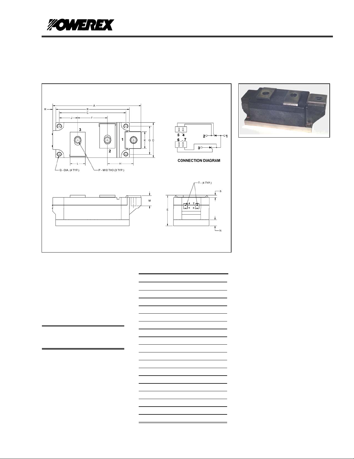
OUTLINE DRAWING
PRELIMINARY
LDR3__50
POW-R-BLOK
Dual SCR Isolated Module
TM
Ordering Information:
Select the complete eight-digit
module part number from the table
below.
Example: LDR31650 is a 1600V,
500 Ampere Dual SCR Isolated
POW-R-BLOK
TM
Module.
Type
LDR3 08
Voltage
Volts
(x100)
10
12
14
16
18
Current
Amperes
(x10)
50
LDR3 Outline Dimensions
Dimension Inches Millimeters
A 5.87 149
B 4.88 124
C 4.41 112
D 2.36 60
E 2.05 52
F 1.97 50
G 1.89 48
H 1.73 44
J 1.22 31
K 1.10 28
L 1.02 26
M 0.67 17
N 0.39 10
P M10 Metric M10
Q 0.26 Dia. 6.5 Dia.
R 0.20 5
S 0.12 3
T .110 x .032 2.8 x 0.8
Note: Dimensions are for reference only.
LDR3__50
Dual SCR
POW-R-BLOKTM Module
500 Amperes / 800-1800 Volts
Description:
Powerex Dual SCR Modules are
designed for use in applications
requiring phase control and isolated
packaging. The modules are isolated
for easy mounting with other
components on a common heatsink.
POW-R-BLOK
recognized by the Underwriters
Laboratories.
Features:
Electrically Isolated Heatsinking
Compression Bonded Elements
Metal Baseplate
Low Thermal Impedance
for Improved Current Capability
Includes Gate Lead Kits and
M10 Terminal Hardware
UL Recognition Pending
RoHS Compliant
Benefits:
No Additional Insulation
Components Required
Easy Installation
No Clamping Components
Required
Reduce Engineering Time
Applications:
Bridge Circuits
AC & DC Motor Drives
Battery Supplies
Power Supplies
Large IGBT Circuit Front Ends
TM
has been tested and
Revision Date: 7/21/2017
Page 2

A
A
PRELIMINARY
LDR3__50
POW-R-BLOK
TM
Dual SCR Isolated Module
500 Amperes / Up to 1800 Volts
Absolute Maximum Ratings
Characteristics Conditions Symbol Units
Repetitive Peak Forward and Reverse Blocking
Voltage
Non-Repetitive Peak Blocking Voltage
(t < 5 msec)
RMS Forward Current 180° Conduction, TC=85°C, 50 Hz I
verage Forward Current 180° Conduction, TC=85°C, 50 Hz I
Peak One Cycle Surge Current, Non-Repetitive 60 Hz, 0V reapplied, Tj= T
60 Hz, 0V reapplied, Tj= 25 °C I
50 Hz, 0V reapplied T
50 Hz, 0V reapplied, T
2
t for Fusing for One Cycle 60 Hz, 0V reapplied, Tj= T
I
60 Hz, 0V reapplied, Tj= 25 °C
50 Hz, 0V reapplied T
50 Hz, 0V reapplied, T
verage Forward Gate Power P
Maximum Rate-of-Rise of On-State Current,
T= T
(Repetitive)
Gate Pulse: I
Operating Temperature TJ -40 to +130 °C
Storage Temperature T
Max. Mounting Torque, M6 Mounting Screw 55
Max. Mounting Torque, M10 Terminal Screw 110
Module Weight, Typical 1.5 kg
3.30 lb
V Isolation @ 25C t= 1 minute, 50 Hz
Information presented is based upon manufacturers testing and projected capabilities.
This information is subject to change without notice.
The manufacturer makes no claim as to the suitability of use, reliability, capability,
or future availability of this product.
V
V
I
j max
= T
I
j
j max
= 25 °C I
j
j max
= T
j
j max
= 25 °C
j
, VD= 0.67 V
j max
I
= 2 I
TM
TAV
= 2 A, tGP= 50 µs,
G
di
/dt>= 1 A/µs
G
,
DRM
,
& V
DRM
up to 1800 V
RRM
V
RSM
785 A
T(RMS)
T(AV)
TSM
TSM
15,500 A
TSM
18,000 A
TSM
2
t
I
2
t
I
2
t
I
2
t
I
4 W
G(AV)
di/dt 400 A/µs
-40 to +125 °C
stg
V
rms
+ 100 V
RRM
500 A
17,000 A
20,000 A
1.19 x 10
1.66 x 10
1.20 x 10
1.62 x 10
6
6
6
6
2
A
sec
2
A
sec
A2 sec
2
A
sec
in. – Lb.
6
Nm
in. – Lb.
12
Nm
3000 V
Revision Date: 7/21/2017
Page 3

/
PRELIMINARY
LDR3__50
POW-R-BLOK
TM
Dual SCR Isolated Module
500 Amperes / Up to 1800 Volts
Electrical Characteristics, TJ=25°C unless otherwise specified
Characteristics Sy mbol Test Conditions Min. Max. Units
Repetitive Peak Forward Leakage Current I
Repetitive Peak Reverse Leakage Current I
Peak On-State Voltage VFM I
Threshold Voltage, Low-level
Slope Resistance, Low-level
VTM Coefficients, Full Range
Critical Rate of Rise of Off-State Voltage dV/dt VD= 0.67 V
Gate Trigger Current IGT T
Gate Trigger Voltage VGT T
Non-Triggering Gate Voltage V
Peak Forward Gate Current I
Peak Reverse Gate Voltage V
Latching Current IL T
V
DRM
V
RRM
V
(TO)1
r
T1
T
TJ = 130°C, I = 0.5 πI
T
GDM
4.0 A
GTM
5 V
GRM
Gate Pulse: I
= V
, , TJ=130°C 70 mA
D
DRM
= V
, TJ=130°C 70 mA
R
RRM
=1570A 1.50 V
TM
= 130°C, I = 0.5 πI
J
T(AV)
T(AV)
V
= A+ B Ln I +C I + D Sqrt I
TM
=130°C, Gate Open 1000 V/µs
DRM , Tj
=25°C, VD=12V 250 mA
j
=25°C, VD=12V 2.5 V
j
=130°C, VD= 0.67 V
j
= 25 °C, VD= 12 V,
j
= 2 A, tGP= 50 µs, di
G
to 1.5 πI
to 1.5 πI
T(AV)
T(AV)
0.25 V
DRM
dt>=
G
1 A/µs
Holding Current IH T
Turn-Off Time tq Itm=I
= 25 °C, VD= 0.67 V
j
, dI/dt=10 A/us, dVD/dt=50 V/us,
TAV
V
=0.67 Vdrm, VR= 100 V, Tj=130oC
D
, Gate Open 300 mA
DRM
Thermal Characteristics
Characteristics Sy mbol
Thermal Resistance, Junction to Case
Thermal Impedance Coefficients
R
Z
ΘJ-C
Θ
J-C
Thermal Resistance, Case to Sink Lubricated
R
ΘC-S
Per Module, both conducting
Per Junction, both conducting
Z
Θ
J-C
+ K
+ K
+ K
= K1 (1-exp(-t/1))
(1-exp(-t/2))
2
(1-exp(-t/3))
3
(1-exp(-t/4))
4
= 7.42E-04
K
1
K2 = 9.52E-04
K3 = 1.02E-02
K4 = 5.23E-02
Per Module 0.01 °C/W
0.85
0.40
A =
B =
C =
D =
-2.5548
0.8017
9.55E-04
-0.0851
1000 mA
250 µs
Max. Units
0.0325
0.0650
= 3.33E-04
1
2 = 4.74E-03
3 = 9.60E-02
4 = 1.719
Revision Date: 7/21/2017
V
mΩ
°C/W
°C/W
Page 4

PRELIMINARY
Dual SCR Isolated Module
500 Amperes / Up to 1800 Volts
5
4
3
2
On-State Voltage - Vtm - Volts
1
0
100 1000 10000 100000
Maximum On-State Forward Voltage Drop
( Tj = 130 °C )
Instantaneous On-State Current - Itm - Amperes
LDR3__50
POW-R-BLOK
Maximum Transient Thermal Impedance
0.07
0.06
0.05
0.04
0.03
0.02
Thermal Impedance - Rjc - °C/W
0.01
0
0.001 0.01 0.1 1 10 100
(Junction to Case)
Time -t -Seconds
TM
Maximum On-State Power Dissipation
800
700
600
500
400
300
200
100
Maximum Power Dissipation Per SCR - Watts
0
0 100 200 300 400 500 600
1000
900
800
700
600
500
400
300
200
100
Maximum Power Dissipation Per SCR - Watts
0
0 100 200 300 400 500 600 700 800 900
15°
15°
(Sinusoidal Waveform)
120°
90°
60°
30°
Average On-State Current - If(av) - Amperes
Maximum On-State Power Dissipation
(Rectangular Wa veform)
180°
120°
90°
60°
30°
Average On-State Current - It(av) - Amperes
270°
180°
360°
Maximum Allowable Case Temperature
140
130
120
110
100
90
Max. Case Temperature - Tcase - °C
80
70
0 100 200 300 400 500 600
15°
(Sinusoidal Waveform)
30°
Average On-State Current - It(av) - Amperes
60°
90°
120°
180°
Maximum Allowable Case Temperature
140
130
120
110
100
90
80
70
Max. Case Temperature - Tcase - °C
60
50
0 100 200 300 400 500 600 700 800 900
15°
(Rectangular Waveform)
30°
60°
90°
120°
180°
Average On-State Current - It(av) - Amperes
270°
360° (DC)
Revision Date: 7/21/2017
 Loading...