

Page 1
Powerex, Inc., 173 Pavilion Lane, Youngwood, Pennsylvania 15697 (724) 925-7272 POW-R-BLOK
www.pwrx.com
Dual SCR Isolated Module
LD83__24
TM
240 Amperes / Up to 4000 Volts
R
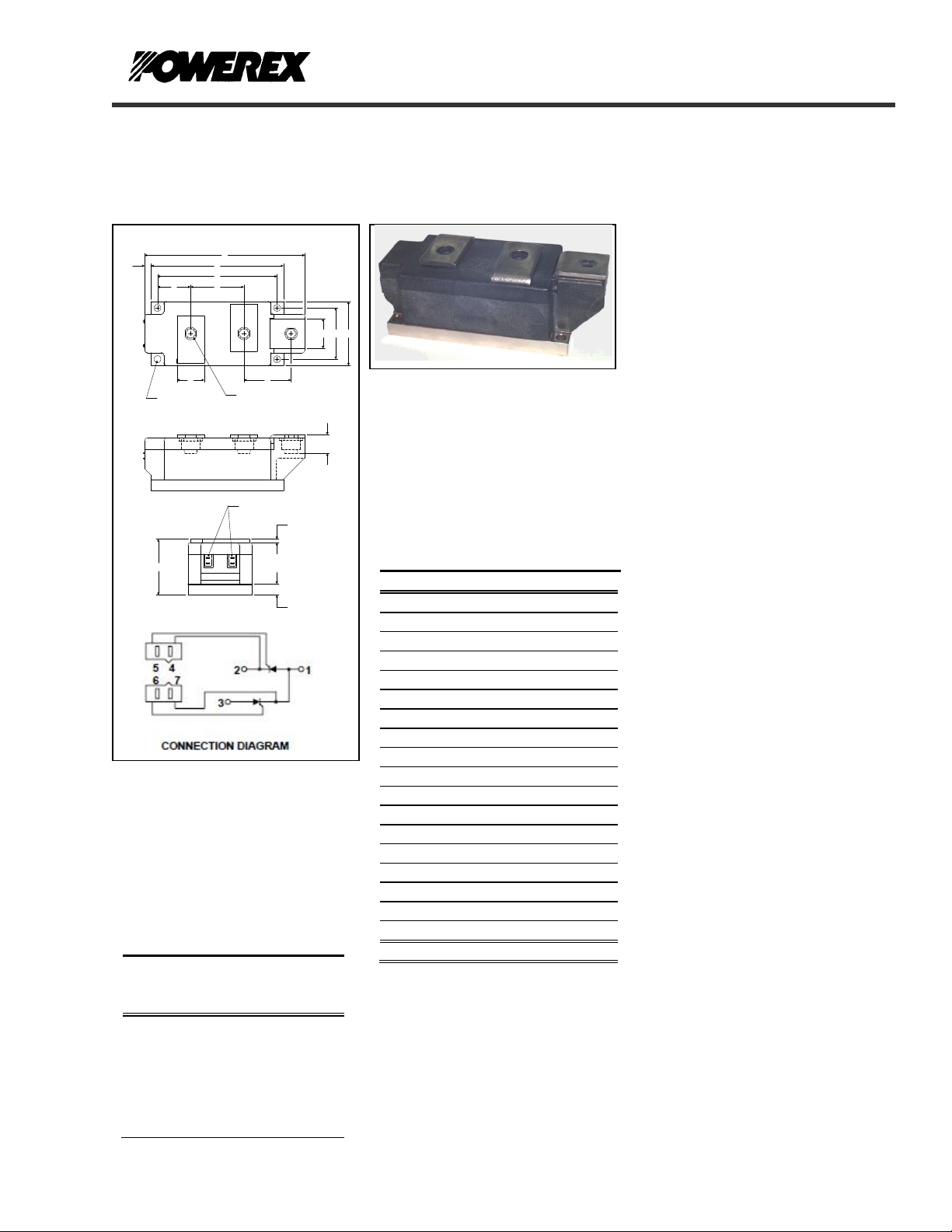
OUTLINE DRAWING
J F
3
L H
Q - DIA. (4 TYP.)
E
B
C
4
56
A
7
2
P - M10 THD (3 TYP.)
T - (4 TYP.)
1
S
N
Ordering Information:
Select the complete eight-digit
module part number from the table
below.
Example: LD834024 is a 4000V,
240 Ampere Dual SCR Isolated
POW-R-BLOK
TM
Module.
Type
LD83
Voltage
Volts
(x100)
40
38
36
Current
Amperes
(x10)
24
K D
G
M
LD83__24
Dual SCR
POW-R-BLOKTM Module
240 Amperes / 4000 Volts
LD83 Outline Dimensions
Dimension Inches Millimeters
A 5.91 150.0
B 4.88 124.0
C 4.41 112.0
D 2.36 60.0
E 2.05 52.0
F 1.97 50.0
G 1.89 48.0
H 1.73 44.0
J 1.22 31.0
K 1.10 28.0
L 1.00 25.4
M 0.69 17.5
N 0.39 10.0
P M10 Metric M10
Q 0.26 Dia. 6.5 Dia.
R 0.24 6.0
S 0.12 3.0
T .110 x .032 2.5 x 0.8
Note: Dimensions are for reference only.
Description:
Powerex Dual SCR Modules are
designed for use in applications
requiring phase control and isolated
packaging. The modules are isolated
for easy mounting with other
components on a common heatsink.
Features:
Electrically Isolated Heatsinking
Aluminum Nitride Isolator
Compression Bonded Elements
Metal Baseplate
Low Thermal Impedance
for Improved Current Capability
Benefits:
No Additional Insulation
Components Required
Easy Installation
No Clamping Components
Required
Reduce Engineering Time
Applications:
Bridge Circuits
AC & DC Motor Drives
Battery Supplies
Power Supplies
Large IGBT Circuit Front Ends
Revision Date: 01/23/2008
Page 2
A
j
j
2
2
Powerex, Inc., 173 Pavilion Lane, Youngwood, Pennsylvania 15697 (724) 925-7272 POW-R-BLOK
www.pwrx.com
Dual SCR Isolated Module
240 Amperes / Up to 4000 Volts
LD83__24
TM
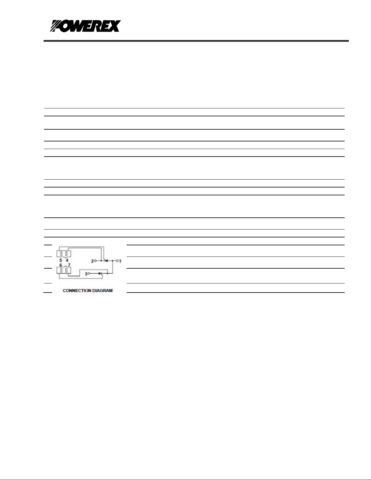
Absolute Maximum Ratings
Characteristics Conditions Symbol Units
& V
Repetitive Peak Forward and Reverse Blocking
V
DRM
Voltage
Non-Repetitive Peak Blocking Voltage
V
(t < 5 msec)
RMS Forward Current
I
verage Forward Current 180° Conduction, TC=74°C I
Peak One Cycle Surge Current, Non-Repetitive
60 Hz, 100% V
50 Hz, 100% V
60 Hz, No V
50 Hz, No V
Peak Three Cycle Surge Current, Non-Repetitive 60 Hz, 100%V
Peak Ten Cycle Surge Current, Non-Repetitive 60 Hz, 100% V
I2t for Fusing for One Cycle
60 Hz, 100% V
50 Hz, 100% V
60 Hz, No V
50 Hz, No V
Maximum Rate-of-Rise of On-State Current,
Per JEDEC Standard 397 5.2.2.6
reapplied, T
RRM
reapplied, T
RRM
reapplied, T
RRM
reapplied, T
RRM
reapplied I
RRM
reapplied I
RRM
reapplied, T
RRM
reapplied, T
RRM
reapplied, T
RRM
reapplied, T
RRM
jmax
max
jmax
max
jmax
jmax
jmax
jmax
(Repetitive)
Operating Temperature TJ -40 to +125 °C
Storage Temperature T
Max. Mounting Torque, M6 Mounting Screw
Max. Mounting Torque, M10 Terminal Screw
Module Weight, Typical 1500 g
3.30 lb
V Isolation @ 25C
Information presented is based upon manufacturers testing and projected capabilities.
This information is subject to change without notice.
The manufacturer makes no claim as to the suitability of use, reliability, capability,
or future availability of this product.
up to 4000 V
RRM
V
RSM
377
T(RMS)
240 A
T(AV)
I
TSM
I
TSM
I
TSM
I
TSM
4416 A
TSM
3470 A
TSM
I
t
2
I
t
2
t
I
2
I
t
+ 100 V
RRM
5500
5019
8250
7528
126,000
105,000
283,000
236,000
A
A
A
A
A
A
sec
2
A
sec
2
sec
A
2
A
sec
di/dt 150 A/µs
-40 to +150 °C
stg
55
6
110
12
V
rms
3600 V
in. – Lb.
Nm
in. – Lb.
Nm
Revision Date: 01/23/2008
Page 3

Powerex, Inc., 173 Pavilion Lane, Youngwood, Pennsylvania 15697 (724) 925-7272 POW-R-BLOK
www.pwrx.com
Dual SCR Isolated Module
240 Amperes / Up to 4000 Volts
LD83__24
TM
Electrical Characteristics, TJ=25°C unless otherwise specified
Characteristics Symbol Test Conditions Min.
Repetitive Peak Forward Leakage Current I
Repetitive Peak Reverse Leakage Current I
Peak On-State Voltage VFM I
Threshold Voltage, Low-level
Slope Resistance, Low-level
VTM Coefficients, Full Range
Up to 4000V, TJ=125°C 75 mA
DRM
Up to 4000V, TJ=125°C 75 mA
RRM
=1000A 3.5 V
TM
V
(TO)1
r
T1
T
= 125°C, I = 15%I
J
= 125°C, I = 10A to 6kA
T
J
V
= A+ B Ln I +C I + D Sqrt I
TM
T(AV)
to πI
T(AV)
A =
B =
C =
D =
Minimum dV/dt dV/dt
Typical Turn-off Time tq V
Exponential to V
=125°C, Gate Open
T
j
= 100 V, dIR/dt= 5 A/µs Reapplied
R
DRM
dv/dt= 20V/µs Linear to 50% V
Gate Trigger Current IGT T
Gate Trigger Voltage VGT T
Non-Triggering Gate Voltage V
Peak Forward Gate Current I
Peak Reverse Gate Voltage V
T
GDM
4.0 Amp
GTM
5 Volts
GRM
=25°C, VD=12V 200 mA
j
=25°C, VD=12V 3.0 Volts
j
=125°C, VD= ½ V
j
DRM
0.25 Volts
1000 Typ. V/µs
250 Typ µs
DRM
Max.
1.563
2.141
0.9479
0.03929
3.980 E-04
0.06093
Units
V
mΩ
Thermal Characteristics
Characteristics Symbol
Thermal Resistance, Junction to Case
Thermal Impedance Coefficients
Thermal Resistance, Case to Sink Lubricated
R
Z
R
ΘJ-C
ΘJ-C
ΘC-S
Per Module, both conducting
Per Junction, both conducting
Z
= K1 (1-exp(-t/τ1))
ΘJ-C
+ K
(1-exp(-t/τ2))
2
(1-exp(-t/τ3))
+ K
3
+ K
(1-exp(-t/τ4))
4
Per Module 0.01 °C/W
K
= 8.03E-04
1
K2 = 1.03E-02
K3 = 1.64E-02
K4 = 3.75E-02
Max.
0.0325
0.0650
τ
= 3.39E-04
1
τ2 = 3.15E-03
τ3 = 0.106
τ
= 2.066
4
Units
°C/W
°C/W
Revision Date: 01/23/2008
Page 4

Powerex, Inc., 173 Pavilion Lane, Youngwood, Pennsylvania 15697 (724) 925-7272 POW-R-BLOK
www.pwrx.com
Dual SCR Isolated Module
LD83__24
TM
240 Amperes / Up to 4000 Volts
Maximum On-State Forwar d Voltage Drop
5
4
3
2
On-State Voltage - Vtm - Volts
1
0
10 100 1000 10000
Instantaneous On-State Current - Itm - Amperes
( Tj = 125 C )
Maximum On-State Power Dissipation
800
700
600
500
400
300
200
100
Maximum Power Dissi pation Per SCR -Watts
0
0 50 100 150 200 250 300
(Sinusoida l Wav efor m)
180°
120°
90°
60°
30°
15°
Aver age On-St ate Curr ent -It(av ) - Amperes
Maximum Transient Ther mal Im pedance
0.07
0.06
0.05
0.04
0.03
0.02
Thermal I mpedance -Rjc - °C/W
0.01
0
0.0001 0.001 0.01 0.1 1 10
(Junction t o Case)
Time -t - Seconds
Maximum Allow able C ase Temperature
130
120
110
100
90
80
Max. Case T emperatur e -Tcase - °C
70
60
0 50 100 150 200 250 300
(Sinusoida l Wav efor m)
15°
30°
Aver age On-St ate Curr ent -It(av ) - Amperes
60°
90°
120°
180°
Maximum On-State Power Dissipation
1200
1000
800
600
400
200
Maximum Power Dissi pation Per SCR -Watts
0
0 50 100 150 200 250 300 350 400
15°
(Rectangu lar Wav eform )
180°
120°
90°
60°
30°
Aver age On-St ate Curr ent -It(av ) - Amperes
270°
360°
Maximum Allow able C ase Temperature
130
120
110
100
90
80
70
60
Max. Case Tem peratur e -Tcase -°C
50
40
0 40 80 120 160 200 240 280 320 360 400
15°
(Rectangu lar Wav efor m)
30°
60°
90°
120°
180°
Aver age On-St ate Curr ent -It(av ) - Amperes
270°
Revision Date: 01/23/2008
360°C
 Loading...