

Page 1
MITSUBISHI HVIGBT MODULES
Prepared by
Date
th
3
-Version HVIGBT (High Voltage Insulated Gate Bipolar Transistor) Modules INSULATED TYPE
K.Kurachi
I.Umezaki 24-Feb.-2009
Revision: B
CM400E4G-130H
HIGH POWER SWITCHING USE
CM400E4G-130H
● IC ……………………… 400 A
● V
CES
● 1-element in a Pack (for brake chopper)
● Insulated Type
● AlSiC Baseplate
APPLICATION
Traction drives, High Reliability Converters / Inverters, DC choppers
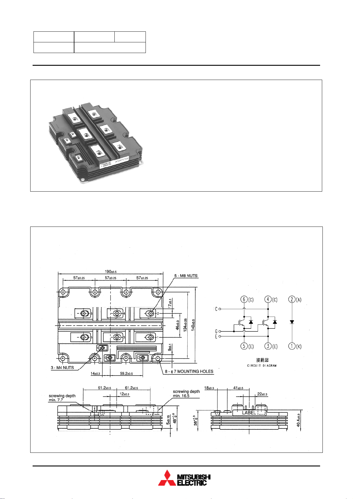
OUTLINE DRAWING & CIRCUIT DIAGRAM
…………………… 6500 V
Dimensions in mm
HVIGBT (High Voltage Insulated Gate Bipolar Transistor) MODULES
HVM-1049-B 1 of 8
Page 2
MITSUBISHI HVIGBT MODULES
CM400E4G-130H
th
3
-Version HVIGBT (High Voltage Insulated Gate Bipolar Transistor) Modules INSULATED TYPE
HIGH POWER SWITCHING USE
MAXIMUM RATINGS
Symbol
V
CES
V
GES
IC DC, Tc = 80°C 400 A
ICM
IE DC 400 A
IEM
Pc
V
iso
Ve
Tj
Top
T
stg
t
psc
Collector-emitter voltage
Gate-emitter voltage
Collector current
Emitter current
Maximum power dissipation
Isolation voltage
Partial discharge extinction voltage
Junction temperature
Operating temperature
Storage temperature
Maximum short circuit pulse width
Item
VGE = 0 V
VCE = 0V, Tj = 25°C ± 20 V
(Note 1)
Pulse
(Note 2)
(Note 3)
(Note 1)
Pulse
= 25°C, IGBT part 5900 W
T
c
RMS, sinusoidal, f = 60Hz, t = 1 min. 10200 V
RMS, sinusoidal, f = 60Hz, QPD ≤ 10 pC 5100 V
−40 ~ +150 °C
−40 ~ +125 °C
−40 ~ +125 °C
V
=4500V, VCE ≤ V
CC
Conditions Ratings Unit
Tj = -40 °C 5800
Tj = +25 °C 6300
= +125 °C 6500
T
j
V
800 A
800 A
, VGE =15V, Tj =125°C
CES
10 µs
ELECTRICAL CHARACTERISTICS
Symbol
I
CES
V
GE(th)
I
GES
C
ies
C
oes
C
res
Qg
V
CE(sat)
t
d(on)
tr
E
on(10%)
t
d(off)
tf
tf2
E
off(10%)
VEC
trr
t
Reverse recovery time
rr2
Collector cutoff current V
Gate-emitter threshold voltage V
Gate leakage current V
Input capacitance
Output capacitance
Reverse transfer capacitance
Total gate charge
Collector-emitter saturation voltage
Turn-on delay time
Turn-on rise time
Turn-on switching energy
Turn-off delay time
Turn-off fall time
Turn-off fall time
Turn-off switching energy
Emitter-collector voltage
Reverse recovery time
Item Conditions
Qrr Reverse recovery charge
E
Reverse recovery energy
rec(10%)
(Note 2), (Note 5)
Min Typ Max
= V
CE
CE
GE
, VGE = 0V
CES
= 10 V, IC = 40 mA, Tj = 25°C
= V
, VCE = 0V, Tj = 25°C
GES
Tj = 25°C
= 125°C
T
j
— — 7
— 20 60
5.0 6.0 7.0 V
−0.5 — 0.5 µA
— 82.0 — nF
= 10 V, VGE = 0 V, f = 100 kHz
V
CE
= 25°C
T
j
V
= 3600 V, IC = 400 A
CC
V
= ±15 V, Tj = 25 °C
GE
= 400 A
I
C
V
GE
V
CC
V
GE
= 125 °C, Ls = 170 nH
T
(Note 5)
(Note 5)
(Note 2)
(Note 2)
(Note 2)
(Note 2)
j
t
(IGBT_off)
V
CC
V
GE
= 125 °C, Ls = 170 nH
T
j
Inductive load
I
= 400 A
E
VGE = 0 V
V
CC
— 2.4 — µs
V
GE
= 125 °C, Ls = 170 nH
T
j
— 740 — µC
t
(IGBT_off)
(Note 4)
= 15 V
= 3600 V, IC = 400 A
= ±15 V, R
= 60 µs
G(on)
(Note 6)
= 3600 V, IC = 400 A
= ±15 V, R
G(off)
(Note 4)
= 3600 V, IE = 400 A
= ±15 V, R
= 60 µs
G(on)
(Note 6)
Tj = 25°C
T
= 125°C
j
= 15 Ω
, Inductive load
= 50 Ω
Tj = 25 °C
T
= 125 °C
j
= 15 Ω
, Inductive load
— 5.0 — nF
— 1.4 — nF
— 6.6 — µC
— 4.5 —
— 4.6 —
— 1.2 — µs
— 0.35 — µs
— 3.0 — J/P
— 8.2 — µs
— 0.5 — µs
— 3.1 — µs
— 2.7 — J/P
— 4.0 —
— 3.6 —
— 1.0 — µs
— 1.4 — J/P
Limits
Unit
mA
V
V
HVIGBT (High Voltage Insulated Gate Bipolar Transistor) MODULES
HVM-1049-B 2 of 8
Page 3
MITSUBISHI HVIGBT MODULES
CM400E4G-130H
th
3
-Version HVIGBT (High Voltage Insulated Gate Bipolar Transistor) Modules INSULATED TYPE
HIGH POWER SWITCHING USE
THERMAL CHARACTERISTICS
Symbol Item Conditions
Min Typ Max
R
Thermal resistance Junction to Case, IGBT part — — 21.0 K/kW
th(j-c)Q
Junction to Case, FWDi part — — 33.0 K/kW
R
Thermal resistance
th(j-c)R
R
Contact thermal resistance
th(c-f)
Junction to Case, Clamp-Di part — — 33.0 K/kW
Case to Fin,
λ
= 1W/m·K, D
grease
= 100 µm
(c-f)
— 9.0 — K/kW
Limits
Unit
MECHANICAL CHARACTERISTICS
Symbol Item Conditions
Min Typ Max
Mt M8: Main terminals screw 7.0 — 15.0 N·m
Ms M6: Mounting screw 3.0 — 6.0 N·m
Mt
Mounting torque
M4: Auxiliary terminals screw 1.0 — 3.0 N·m
m Mass — 1.35 — kg
CTI Comparative tracking index 600 — — —
da Clearance 26.0 — — mm
Limits
Unit
ds Creepage distance 56.0 — — mm
Collector to Emitter — 27.0 — nH
L
Parasitic stray inductance
P CE
Anode to Cathode — 54.0 — nH
Tc = 25°C, Collector to Emitter — 0.19 — mΩ
R
Internal lead resistance
CC’+EE’
Note 1. Pulse width and repetition rate should be such that junction temperature (T
Note 2. The symbols represent characteristics of the anti-parallel, emitter to collector free-wheel diode (FWDi) and the brake chopper,
T
= 25°C, Anode to Cathode — 0.38 — mΩ
c
) does not exceed T
j
rating (125°C).
opmax
anode to cathode clamp diode (Clamp-Di).
Note 3. Junction temperature (T
Note 4. Pulse width and repetition rate should be such as to cause negligible temperature rise.
Note 5. E
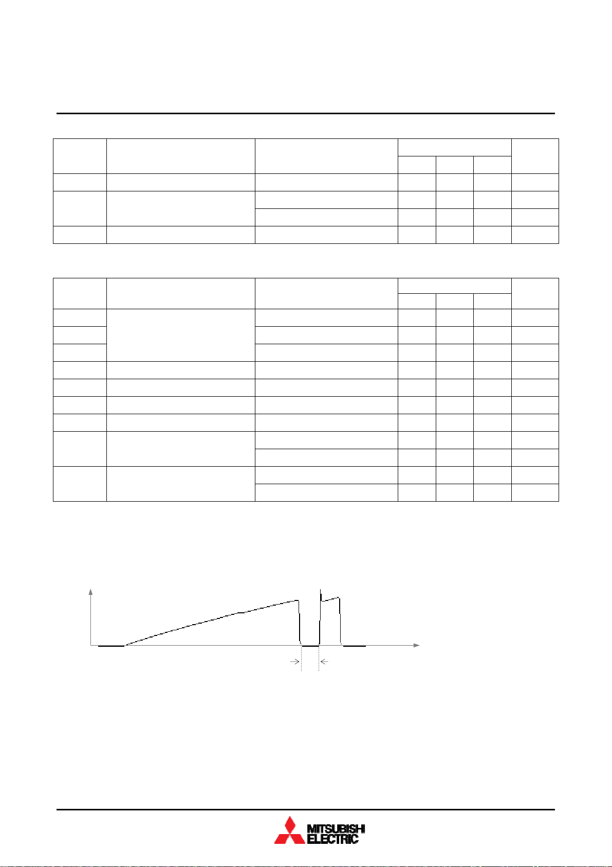
Note 6. t
IC
on(10%)
(IGBT_off)
/ E
/ E
off(10%)
definition is shown as follows.
) should not exceed T
j
are the integral of 0.1VCE x 0.1IC x dt.
rec(10%)
rating (150°C).
jmax
t
(IGBT_off)
time
HVIGBT (High Voltage Insulated Gate Bipolar Transistor) MODULES
HVM-1049-B 3 of 8
Page 4

MITSUBISHI HVIGBT MODULES
∫
∫
∫
∫
CM400E4G-130H
th
3
-Version HVIGBT (High Voltage Insulated Gate Bipolar Transistor) Modules INSULATED TYPE
HIGH POWER SWITCHING USE
10%VGE
0
VGE
VCC
90%V
GE
t2
t1
IC
VCE
ic•vce dt
10%V
di
CE
90%IC
50%IC
dt
tf2 td(off)
t3 t4
10%IC
Eoff =
tf = (0.9ic − 0.1ic) / (di/dt)
toff = td(off) + tf
0
90%IC
10%IC
tr td(on)
ton
t1 t2
10%VCE
Eon =
Fig. 2 – Definitions of switching times & energies of IGBT part
t4
t3
ic•vce dt
IE (IF)
0
0
di
Irr
di/dt
trr
dt
10%V
EC
10%IE
VEC (VR)
Qrr
Erec
= –
= –
t6
0
t6
t5
ie dt
ie•vec dt
0
trr2
t5 t6
Fig. 3 – Definitions of reverse recovery charge & energy of FWDi part
HVIGBT (High Voltage Insulated Gate Bipolar Transistor) MODULES
HVM-1049-B 4 of 8
Page 5

MITSUBISHI HVIGBT MODULES
CM400E4G-130H
th
3
-Version HVIGBT (High Voltage Insulated Gate Bipolar Transistor) Modules INSULATED TYPE
HIGH POWER SWITCHING USE
PERFORMANCE CURVES
OUTPUT CHARACTERISTICS
800
Tj = 125°C
600
400
Collector Current [A]
200
(TYPICAL)
VGE = 20V
VGE = 15V
VGE = 12V
VGE = 10V
VGE = 8V
TRANSFER CHARACTERISTICS
(TYPICAL)
800
VCE = V
GE
600
400
Collector Current [A]
200
Tj = 125°C
Tj = 25°C
0
012345678
Collector - Emitter Voltage [V]
0
024681012
Gate - Em itter Voltage [V]
COLLECTOR-EMITTER SATURATION VOLTAGE
CHARACTERISTICS (TYPICAL)
800
VGE = 15V
600
400
Collector Current [A]
200
Tj = 125°CTj = 25°C
FREE-WHEEL DIODE FORWARD
CHARACTERISTICS (TYPICAL)
800
600
400
Emitter Current [A]
200
Tj = 25°CTj = 125°C
0
02468
Collector-Em itter Satura tion Voltage [V]
HVIGBT (High Voltage Insulated Gate Bipolar Transistor) MODULES
0
02468
Emitter-Collector Voltage [V]
HVM-1049-B 5 of 8
Page 6

th
3
-Version HVIGBT (High Voltage Insulated Gate Bipolar Transistor) Modules
PERFORMANCE CURVES
CAPACITANCE CHARACTERISTICS
(TYPICAL)
1000
100
10
Cies
Coes
MITSUBISHI HVIGBT MODULES
CM400E2G-130H
HIGH POWER SWITCHING USE
INSULATED TYPE
GATE CHARGE CHARACTERISTICS
(TYPICAL)
20
VCE = 3600V, IC = 400A
Tj = 25°C
15
10
5
0
Capacitance [nF]
1
VGE = 0V, Tj = 25°C
f = 100kHz
0
0.1 1 10 100
Collector-Emitter Voltage [V]
HALF-BRIDGE SWITCHING ENERGY
CHARACTERISTICS (TYPICAL)
7
VCC = 3600V, VGE = ±15V
R
= 15Ω, R
G(on)
LS = 170nH , Tj = 125° C
6
Inductive load
5
4
3
2
Switching Energies [J/P]
1
G(off)
= 50Ω
Eon
Eoff
Erec
Cres
-5
Gate-Emitter Voltage [V]
-10
-15
024681
0
Gate Charge [µC]
HALF-BRIDGE SWITCHING ENERGY
CHARACTERISTICS (TYPICAL)
8
VCC = 3600V, IC = 400A
VGE = ±15V , LS = 170nH
7
Tj = 125°C, Induct ive l oad
6
5
4
3
2
Switching Energies [J/P]
1
Eon
Eoff
Erec
0
0 200 400 600 800 1000
Collector Current [A]
HVIGBT (High Voltage Insulated Gate Bipolar Transistor) MODULES
0
0 20406080100
Gate res is tor [Ohm]
HVM-1049-B 6 of 8
Page 7

th
3
-Version HVIGBT (High Voltage Insulated Gate Bipolar Transistor) Modules
PERFORMANCE CURVES
HALF-BRIDGE SWITCHING TIME
CHARACTERISTICS (TYPICAL)
100
VCC = 3600V, VGE = ±15V
R
L
Inductive load
10
= 15Ω, R
G(on)
= 170nH , Tj = 125° C
S
G(off)
= 50Ω
td(off)
td( on)
MITSUBISHI HVIGBT MODULES
CM400E2G-130H
HIGH POWER SWITCHING USE
FREE-WHEEL DIODE REVERSE RECOVERY
CHARACTERISTICS (TYPICAL)
100
VCC = 3600V, VGE = ±15V
R
= 15Ω, LS = 170nH
G(on)
Tj = 125°C, Induct ive l oad
10
INSULATED TYPE
10000
Irr
1000
1
Switching Times [µs]
0.1
0.01
10 100 1000
tf
tr
Collector Current [A]
TRANSIENT THERMAL IMPEDANCE
CHARACTERISTICS
1.2
Rth(j -c) Q = 21.0K/ kW
Rth(j -c) R = 33. 0K/kW
1
0.8
0.6
0.4
0.2
trr
1
Reverse Recovery Time [µs]
0.1
10 100 1000
100
Reverse Recovery Current [A]
10
Emitter Current [A]
⎞
⎛
t
⎫
⎟
⎜
−
⎪
⎟
⎜
τ
i
⎠
⎝
⎬
⎪
⎭
[K/kW] :
R
i
[sec] :
τ
i
⎧
n
=
)t(
−
⎪
⎨
−
∑
RZ
1i
=
1234
0.0096 0.1893 0.4044 0.3967
0.0001 0.0058 0.0602 0.3512
exp1
i)cj(th
⎪
⎩
Normalized Transient Thermal impedance
0
0.001 0.01 0.1 1 10
Tim e [s ]
HVIGBT (High Voltage Insulated Gate Bipolar Transistor) MODULES
HVM-1049-B 7 of 8
Page 8

th
3
-Version HVIGBT (High Voltage Insulated Gate Bipolar Transistor) Modules
PERFORMANCE CURVES
REVERSE BIAS SAFE OPERATING AREA
(RBSOA)
1200
VCC ≤ 4500V, VGE = ±15V
Tj = 125°C, R
1000
800
600
400
Collector Current [A]
200
G(off)
= 50Ω
MITSUBISHI HVIGBT MODULES
CM400E2G-130H
HIGH POWER SWITCHING USE
SHORT CIRCUIT
SAFE OPERATING AREA (SCSOA)
10000
8000
6000
4000
Collector Current [A]
2000
VCC ≤ 4500V, VGE = ±15V
= 15Ω, R
R
G(on)
Tj = 125°C
G(off)
= 50Ω
INSULATED TYPE
0
0 2000 4000 6000 8000
Collector-Emitter Voltage [V]
FREE-WHEEL DIODE REVERSE RECOVERY
SAFE OPERATING AREA (RRSOA)
1200
1000
Reverse Recovery Current [A]
VCC ≤ 4500V, Tj = 125°C
di/dt < 2000A/µ s
800
600
400
200
0
0 2000 4000 6000 8000
Collector-Emitter Voltage [V]
0
0 2000 4000 6000 8000
Collector-Emitter Voltage [V]
HVIGBT (High Voltage Insulated Gate Bipolar Transistor) MODULES
HVM-1049-B 8 of 8
 Loading...