

Page 1
Powerex, Inc., Hillis Street, Youngwood, Pennsylvania 15697 (724) 925-7272 POW-R-BLOK
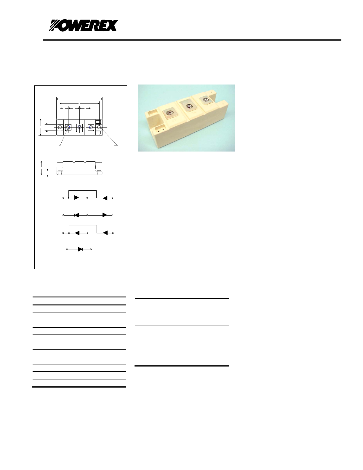
www.pwrx.com Dual & Single Diode Isolated Module
160 Amperes / Up to 2200 Volts
OUTLINE DRAWING
A
D
F F
E
G
B
12
"J" (3)
C
H
CD61
CN61
CC61
CS61
Outline Dimensions
Dimension Inches Millimeters
A 3.70 94
B 1.34 34
C 1.18 30
D 3.15 80
E 0.67 17
F 0.91 23
G 0.51 13
H 0.33 8.3
J M6 M6
K 0.25 6.4
Note: Dimensions are for reference only.
~
1
+
1
+
1
-
1
CONNECTION DIAGRAMS
3
+
2
-
2
-
2
+
2
Ε "K" (2)
-
3
+
3
-
3
CD61__16B, CS61__16B
CN61__16B, CC61__16B
Dual & Single Diode Isolated
POW-R-BLOK
160 Amperes / Up to 2200 Volts
TM
Module
Ordering Information:
Select the complete nine digit module
part number from the table below.
Example: CD611616B is a 1600 Volt,
160 Ampere Dual Diode Isolated
POW-R-BLOK
TM
Module
Current
Amperes
(x 10)
16 B
Type
CD61
CC61
CN61
CS61
Voltage
Volts
(x100)
08
12
14
16
18
20
22
Version
CD61__16B, CS61__16B
CN61__16B, CC61__16B
TM
Description:
Powerex Dual Diode & Single Diode
Modules are designed for use in
applications requiring rectification and
isolated packaging. The modules are
isolated for easy mounting with other
components on a common heatsink.
POW-R-BLOK
recognized by the Underwriters
Laboratories.
TM
has been tested and
Features:
Electrically Isolated Heatsinking
DBC Alumina Insulator
Glass Passivated Chips
Metal Baseplate
Low Thermal Impedance
for Improved Current Capability
UL Recognized (E78240)
Benefits:
No Additional Insulation
Components Required
Easy Installation
No Clamping Components
Required
Reduce Engineering Time
Applications:
Power Supplies
Bridge Circuits
AC & DC Motor Drives
Battery Supplies
Large IGBT Circuit Front Ends
Welders
Revision Date: 04/28/2009
Page 2

A
2
2
Powerex, Inc., Hillis Street, Youngwood, Pennsylvania 15697 (724) 925-7272 POW-R-BLOK
www.pwrx.com Dual & Single Diode Isolated Module
160 Amperes / Up to 2200 Volts
Absolute Maximum Ratings
Characteristics Conditions Symbol Units
Repetitive Peak Reverse Blocking Voltage V
Non-Repetitive Peak Reverse Blocking Voltage
(t < 5 msec)
RMS Forward Current 180° Conduction, TC=109°C
verage Forward Current 180° Conduction, TC=109°C I
Peak One Cycle Surge Current, Non-Repetitive
I2t for Fusing for One Cycle
Operating Temperature TJ -40 to +150 °C
Storage Temperature T
Max. Mounting Torque, M6 Mounting Screw
Max. Mounting Torque, M8 Terminal Screw
Module Weight, Typical 165 g
0.36 lb.
V Isolation @ 25C, V
Information presented is based upon manufacturers testing and projected capabilities.
This information is subject to change without notice.
The manufacturer makes no claim as to the suitability of use, reliability, capability,
or future availability of this product.
for 1 sec V
rms
V
60 Hz, 100% V
60 Hz, 100% No V
50 Hz, 100% V
50 Hz, 100% No V
8.3ms, 100% V
8.3ms, 100% No V
10ms, 100% V
10ms, 100% No V
reapplied, TJ=150C
RRM
reapplied, TJ=150C
RRM
reapplied, TJ=150C
RRM
reapplied, TJ=150C
RRM
reapplied, TJ=150C
RRM
reapplied, TJ=150C
RRM
reapplied, TJ=150C
RRM
reapplied, TJ=150C
RRM
CD61__16B, CS61__16B
CN61__16B, CC61__16B
TM
up to 2200 V
RRM
V
RSM
I
F(RMS)
160 A
F(AV)
I
FSM
I
FSM
I
FSM
I
FSM
I
t
2
I
t
2
I
t
2
I
t
-40 to +150 °C
stg
3000 V
rms
+ 100 V
RRM
250
3,500
4,200
3,350
4,000
52,000
73,000
56,000
80,000
35 - 50
4 – 6
35 - 50
4 – 6
Revision Date: 04/28/2009
A
A
A
A
A
A
sec
2
A
sec
2
A
sec
2
A
sec
in.-Lb.
Nm
in.-Lb.
Nm
Page 3

Powerex, Inc., Hillis Street, Youngwood, Pennsylvania 15697 (724) 925-7272 POW-R-BLOK
www.pwrx.com Dual & Single Diode Isolated Module
160 Amperes / Up to 2200 Volts
Electrical Characteristics, TJ=25°C unless otherwise specified
Characteristics Symbol Test Conditions Min.
Repetitive Peak Reverse Leakage Current I
Peak On-State Voltage VFM I
Threshold Voltage, Low-level
Slope Resistance, Low-level
Thermal Characteristics
Characteristics Symbol
Thermal Resistance, Junction to Case
Thermal Resistance, Case to Sink Lubricated
Up to 2200V, TJ=150°C 20 mA
RRM
=520A, 180 Deg Conduction 1.43 V
FM
V
(TO)1
r
R
R
T1
ΘJ-C
ΘC-S
T
= 150°C, I = 16.7%πI
J
Per Module, both conducting
Per Junction both conducting
Per Module 0.05 °C/W
Max.
CD61__16B, CS61__16B
CN61__16B, CC61__16B
TM
Max.
F(AV)
to πI
F(AV)
0.85
1.2
0.09
0.18
Revision Date: 04/28/2009
Units
V
mΩ
Units
°C/W
°C/W
Page 4

E
Powerex, Inc., Hillis Street, Youngwood, Pennsylvania 15697 (724) 925-7272 POW-R-BLOK
www.pwrx.com Dual & Single Diode Isolated Module
160 Amperes / Up to 2200 Volts
10.00
9.00
8.00
7.00
6.00
5.00
4.00
3.00
2.00
On-State Volta g e - Vtm - Volts
1.00
0.00
10.0 100.0 1000.0 10000.0
Maximum On-State Forward Voltage Drop
Instantaneous On-State Current - Itm - Amperes
250
Maximum On-State Power Dissipation
(Sinusoidal Waveform)
200
150
100
30°
15°
50
Maximum Power Dissipation Per SCR - Watts
0
0 20 40 60 80 100 120 140 160 180
Average On-State Current - It(av) - Amperes
350
300
250
200
150
100
50
Maximum Power Dissipation Per SCR - Watts
0
0 50 100 150 200 250 300
Maximum On-State Power Dissipation
30°
15°
(Rectangular Waveform)
90°
60°
Average On-State Current - It(av) - Amperes
( Tj = 150 °C )
60°
180°
120°
0
CONDUCTION ANGLE
120°
90°
180
0
CONDUCTION ANGLE
270°
180
360
180°
360
360°
.20000
.18000
.16000
.14000
.12000
.10000
.08000
.06000
Thermal Impedance - Rjc - °C/W
.04000
.02000
.00000
.00010 .00100 .01000 .10000 1.00000 10.00000 100.00000
150
145
140
135
130
125
120
115
110
Max. Case Temperature - Tcase - °C
105
100
0 20 40 60 80 100 120 140 160 180
150
140
130
120
110
100
Max. Case Temperature - Tcase - °C
90
0 20 40 60 80 100 120 140 160 180 200 220 240 260
CD61__16B, CS61__16B
CN61__16B, CC61__16B
TM
Maximum Transient Thermal Impedance
Maximum Allowable Case Temperature
15°
Average On-State Current - It(av) - Amperes
Maximum Allowable Case Temperature
15°
Average On-State Current - It(av) - Amperes
(Junction to Case)
Time - t - Seconds
(Sinusoidal Waveform)
30°
(Rectangular Waveform)
30°
60°
180
0
CONDUCTION ANGLE
60°
90°
0
CONDUCTION ANGL
90°
120°
180°
Revision Date: 04/28/2009
120°
180
360
180°
360
270°
360°C
 Loading...