

Page 1
Powerex, Inc., Hillis Street, Youngwood, Pennsylvania 15697 (724) 925-7272
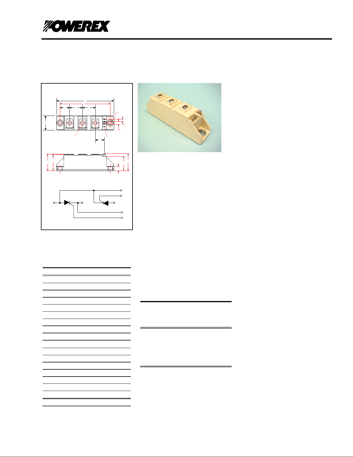
Dual SCR Isolated Module
POW-R-BLOK
90 Amperes / Up to 1800 Volts
OUTLINE DRAWING
A
C
B
D
1
~
"U" THREAD
M
G HF
1
2
2
+
CONNECTION DIAGRAM
3
L
T
67
45
"S" FASTON TAB
N
3
-
J
K
Q
P
CD43__90B
Dual SCR Isolated
POW-R-BLOKTM Module
90 Amperes / Up to 1800 Volts
6
7
5
4
Ordering Information:
Select the complete nine digit module
CD43 Outline Dimensions
Dimension Inches Millimeters
A 3.66 93
B 0.79 20
C 3.15 80
D 1.18 30
F 0.61 15.5
G 0.79 20
H 0.79 20
J 0.16 4
K 0.22 5.7
L 0.59 15
M 1.10 28
N 0.31 8
P 0.94 24
Q 1.16 29.4
S 0.11 x .03 2.8 x 0.8
T 0.25 6.4
U M5 M5
Note: Dimensions are for reference only.
part number from the table below.
Example: CD431690B is a 1600Volt,
90 Ampere Dual SCR Isolated
POW-R-BLOK
TM
Module
Type
CD43 08
Voltage
Volts
(x100)
12
14
16
18
Current
Amperes
90
Version
B
CD43__90B
Description:
Powerex Dual SCR Modules are
designed for use in applications
requiring phase control and isolated
packaging. The modules are isolated
for easy mounting with other
components on a common heatsink.
POW-R-BLOK
recognized by the Underwriters
Laboratories.
Features:
Electrically Isolated Heatsinking
DBC Alumina (Al
Copper Baseplate
Low Thermal Impedance
for Improved Current Capability
UL Recognized (E78240)
Benefits:
No Additional Insulation
Components Required
Easy Installation
No Clamping Components
Required
Reduce Engineering Time
Applications:
Bridge Circuits
AC & DC Motor Drives
Battery Supplies
Power Supplies
Large IGBT Circuit Front Ends
Lighting Control
Heat & Temperature Control
Welders
TM
TM
has been tested and
) Insulator
2O3
Revision Date: 04/28/2009
Page 2
A
Powerex, Inc., Hillis Street, Youngwood, Pennsylvania 15697 (724) 925-7272 POW-R-BLOK
Dual SCR Isolated Module
90 Amperes / Up to 1800 Volts
Absolute Maximum Ratings
Characteristics Conditions Symbol Units
Repetitive Peak Forward and Reverse Blocking
Voltage
Non-Repetitive Peak Reverse Blocking Voltage
(t < 5 msec)
RMS Forward Current
180° Conduction, T
verage Forward Current 180° Conduction, TC=84°C I
Peak One Cycle Surge Current, Non-Repetitive
60 Hz, 100% V
60 Hz, No V
60 Hz, No V
50 Hz, 100% V
50 Hz, No V
50 Hz, No V
I2t for Fusing for One Cycle, 8.3 milliseconds
8.3 ms, 100% V
8.3 ms, No V
8.3 ms, No V
10 ms, 100% V
10 ms, No V
10 ms, No V
Maximum Rate-of-Rise of On-State Current,
(Non-Repetitive)
Operating Temperature TJ -40 to +125 °C
Storage Temperature T
Max. Mounting Torque, M5 Mounting Screw on
Terminals
Max. Mounting Torque, Module to Heatsink
Module Weight, Typical 95 g
3.35 oz.
V Isolation @ 25C
Circuit to base, all terminals shorted together
50 – 60 Hz, 1 minute
50 – 60 Hz, 1 second
Information presented is based upon manufacturers testing and projected capabilities.
This information is subject to change without notice.
The manufacturer makes no claim as to the suitability of use, reliability, capability,
or future availability of this product.
V
V
=84°C I
C
reapplied, Tj=125°C
RRM
reapplied, Tj=125°C
RRM
reapplied, Tj=25°C
RRM
reapplied, Tj=125°C
RRM
reapplied, Tj=125°C
RRM
reapplied, Tj=25°C
RRM
reapplied, Tj=125°C
RRM
reapplied, Tj=125°C
RRM
reapplied, Tj=25°C
RRM
reapplied, Tj=125°C
RRM
reapplied, Tj=125°C
RRM
reapplied, Tj=25°C
RRM
=125°C
T
j
CD43__90B
& V
DRM
RRM
V
RSM
150 A
T(RMS)
95 A
T(AV)
I
TSM
I
TSM
I
TSM
I
TSM
I
TSM
I
TSM
2
I
t
2
I
t
2
t
I
2
t
I
2
t
I
2
t
I
di/dt 150 A/µs
-40 to +125 °C
stg
V
rms
V
rms
TM
up to 1800 V
+ 100 V
RRM
1570
1870
2100
1500
1785
2000
10,270
14,520
18,300
11,250
15,910
20,000
25
3
44
5
3000
3500
A
A
A
A
A
A
2
sec
A
2
A
sec
2
sec
A
2
sec
A
2
sec
A
2
sec
A
in.-Lb.
Nm
in.-Lb.
Nm
V
V
Revision Date: 04/28/2009
Page 3

Powerex, Inc., Hillis Street, Youngwood, Pennsylvania 15697 (724) 925-7272 POW-R-BLOK
Dual SCR Isolated Module
90 Amperes / Up to 1800 Volts
Electrical Characteristics, TJ=25°C unless otherwise specified
Characteristics Symbol Test Conditions Min.
Repetitive Peak Forward Leakage Current I
Repetitive Peak Reverse Leakage Current I
Peak On-State Voltage V TM / VFM I
Threshold Voltage, Low-level
Slope Resistance, Low-level
Minimum dV/dt dV/dt
Turn-Off Time (Typical) t
Gate Trigger Current IGT T
Gate Trigger Voltage VGT T
Non-Triggering Gate Voltage V
Non-Triggering Gate Current I
Up to 1800V, TJ=125°C 20 mA
DRM
Up to 1800V, TJ=125°C 20 mA
RRM
=300A 1.65 V
TM / IFM
V
(TO)1
r
T1
off
T
GDM
T
GDM
= 125°C, I = 16.7% x πI
T
J
T
=125°C, Up to 800V
j
=125°C, 1200 - 1800V
T
j
T
= 25°C
J
= 25°C, VD=6V, Resistive Load 150 mA
j
= 25°C, VD=6V, Resistive Load 3.0 Volts
j
=125°C, VD=V
j
=125°C, VD=V
j
T(AV)
DRM
DRM
Holding Current I H TJ = 25°C 250 mA
Latching Current I L TJ = 25°C 600 mA
Thermal Characteristics
Characteristics Symbol
Thermal Resistance, Junction to Case
DC Operation
Thermal Resistance, Case to Sink Lubricated
R
R
ΘJ-C
ΘC-S
Per Module, both conducting
Per Junction, both conducting
Max.
Per Module 0.1 °C/W
CD43__90B
to πI
T(AV)
0.25 Volts
6 mA
TM
Max.
500
1000
40 - 100 (Typical) µs
0.14
0.28
Revision Date: 04/28/2009
Units
0.9
2.0
V/µs
Units
°C/W
°C/W
V
mΩ
V/µs
Page 4

Powerex, Inc., Hillis Street, Youngwood, Pennsylvania 15697 (724) 925-7272 POW-R-BLOK
Dual SCR Isolated Module
90 Amperes / Up to 1800 Volts
4.00
3.50
3.00
2.50
2.00
1.50
1.00
On-State Voltage - Vtm - Volts
0.50
0.00
10 100 1000
140
120
100
80
60
40
20
Maximum Power Dissipation Per SCR - Watts
0
0 20406080100
Maximum On-State Forward Voltage Drop
Instantaneous On-State Current - Itm - Amperes
Maximum On-State Power Dissipation
15°
( Tj = 125 °C )
(Sinusoidal Waveform)
90°
30°
Average On-State Current - It(av) - Amperes
60°
180
0
CONDUCTION ANGLE
120°
180°
360
Maximum Transient Thermal Impedance
0.30
0.25
0.20
0.15
0.10
Thermal Impedance - Rjc - °C/W
0.05
0.00
0.001 0.01 0.1 1 10 100
Maximum Allowable Case Temperature
125
120
115
110
105
100
95
90
Max. Case Temperature - Tcase - °C
85
80
0 102030405060708090100
CD43__90B
(Junction to Case)
Time - t - Seconds
(Sinusoidal Waveform)
15°
30°
Average On-State Current - It(av) - Amperes
TM
180
0
CONDUCTION ANGLE
60°
90°
120°
360
180°
Maximum On-State Power Dissipation
(Rectangular Waveform)
180
160
140
120
100
80
60
40
20
Maximum Power Dissipation Per SCR - Watts
0
0 10 20 30 40 50 60 70 80 90 100 110 120 130 140 150
30°
15°
Average On-State Current - It(av) - Amperes
60°
90°
180°
120°
0
270°
180
CONDUCTION ANGLE
360
360°
125
120
115
110
105
100
95
90
85
Max. Case Temperature - Tcase - °C
80
75
0 102030405060708090100110120130140150
Maximum Allowable Cas e Temp erature
(Rectangular Waveform)
0
CONDUCTION ANGLE
30°
60°
90°
120°
15°
Average On-State Current - It(av) - Amperes
180°
180
360
270°
360°
Revision Date: 04/28/2009
 Loading...