

Page 1
CD41__99C, CS41__99C
CC41__99C, CN41__99C
®
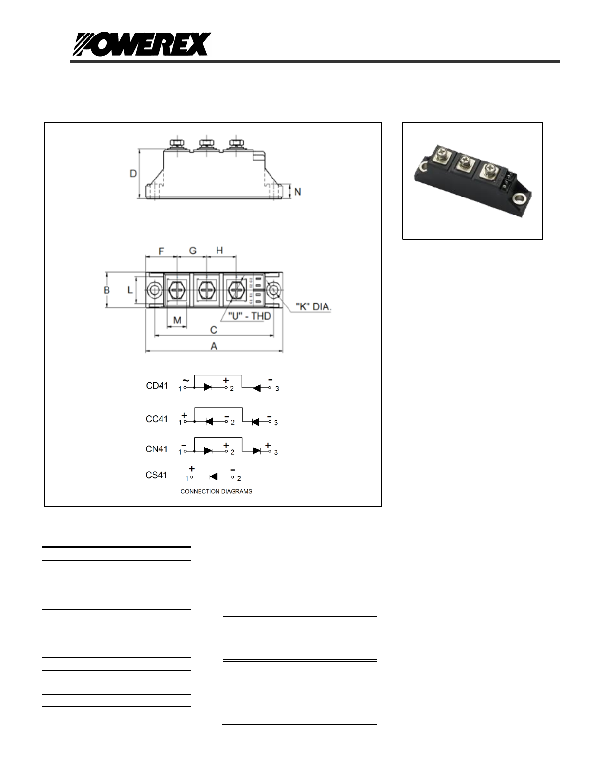
Outline Dimensions
Dimension
Inches
Millimeters
A
3.62
92
B
0.83
21
C
3.15
80
D
1.18
30 F 0.83
21
G
0.79
20
H
0.79
20 K 0.24
6.2
L
0.63
16
M
0.51
13 N 0.33
8.5 U M5
M5
Note: Dimensions are for reference only.
Ordering Information:
Select the complete nine digit module
part number from the table below.
Example: CD412099C is a 2000Volt,
100 Ampere Dual Diode Isolated
POW-R-BLOKTM Module
Type
Voltage
Volts
(x100)
Current
Amperes
Version
CD41
CS41
CC41
CN41
20
22
24
25
99
(100 A)
C
CD41__99C, CS41_99C,
CC41__99C, CN41_99C
Single & Dual Diode Isolated
POW-R-BLOKTM Module
100 Amperes / 2000 to 2500 Volts
Description:
Powerex Single and Dual Diode
Modules are designed for use in
applications requiring rectification and
isolated packaging. The modules are
isolated for easy mounting with other
components on a common heatsink.
Features:
Electrically Isolated Heatsinking
Compression bonded construction
Low Thermal Impedance
for Improved Current Capability
RoHS Compliant
UL Recognized (E78240)
Benefits:
No Additional Insulation
Components Required
Easy Installation
No Clamping Components
Required
Reduce Engineering Time
Applications:
Power Supplies
Bridge Circuits
AC & DC Motor Drives
Battery Supplies
Large IGBT Circuit Front Ends
Lighting Control
Heat & Temperature Control
Welders
Powerex, Inc., 173 Pavilion Lane, Youngwood, Pennsylvania 15697 (724) 925-7272 POW-R-BLOK
http://www.pwrx.com Single & Dual Diode Isolated Module
100 Amperes / 2000 to 2500 Volts
TM
Revision Date: 04/01/2013
Page 2

CD41__99C, CS41__99C
CC41__99C, CN41__99C
®
Absolute Maximum Ratings
Characteristics
Conditions
Symbol
Units
Repetitive Peak Reverse Blocking Voltage
V
RRM
up to 2500
V
Non-Repetitive Peak Reverse Blocking Voltage
(t < 5 msec)
V
RSM
V
RRM
+ 100
V
RMS Forward Current
180° Conduction, TC=101°C
I
F(RMS)
157
A
Average Forward Current
180° Conduction, TC=101°C
I
F(AV)
100
A
Peak One Cycle Surge Current, Non-Repetitive
50 Hz, 60% V
RRM
reapplied, Tj=150°C
I
FSM
2,600
A
I2t for Fusing for One Cycle, 10 milliseconds
50 Hz, 60% V
RRM
reapplied, Tj=150°C
I2t 34,400
A2 sec
Operating Temperature
TJ
-40 to +150
°C
Storage Temperature
T
stg
-40 to +150
°C
Max. Mounting Torque, M5 Mounting Screw on
Terminals
35
4
in.-Lb.
Nm
Max. Mounting Torque, Module to Heatsink
53
6
in.-Lb.
Nm
Module Weight, Typical
160
g
5.64
oz.
V Isolation @ 25C
50 – 60 Hz, 1 minute
50 – 60 Hz, 1 second
V
rms
2500
3000
V
V
Powerex, Inc., 173 Pavilion Lane, Youngwood, Pennsylvania 15697 (724) 925-7272 POW-R-BLOK
http://www.pwrx.com Single & Dual Diode Isolated Module
100 Amperes / 2000 to 2500 Volts
TM
Information presented is based upon manufacturers testing and projected capabilities.
This information is subject to change without notice.
The manufacturer makes no claim as to the suitability of use, reliability, capability,
or future availability of this product.
Revision Date: 04/01/2013
Page 3

CD41__99C, CS41__99C
CC41__99C, CN41__99C
®
Electrical Characteristics, TJ=25°C unless otherwise specified
Characteristics
Symbol
Test Conditions
Min.
Max.
Units
Repetitive Peak Reverse Leakage Current
I
RRM
Up to V
RRM
, TJ=150°C
12
mA
Peak On-State Voltage
V FM
I
FM
=330A
1.65
V
Threshold Voltage, Low-level
Slope Resistance, Low-level
V
(TO)1
rT1
TJ = 150°C, I = 16.7% x I
T(AV)
to I
T(AV)
0.85
1.88
V
mΩ
Thermal Characteristics
Characteristics
Symbol
Max.
Units
Thermal Resistance, Junction to Case
DC Operation
R
ΘJ-C
Per Junction, both conducting
0.35
°C/W
Thermal Resistance, Case to Sink Lubricated
R
ΘC-S
Per Module
0.15
°C/W
Powerex, Inc., 173 Pavilion Lane, Youngwood, Pennsylvania 15697 (724) 925-7272 POW-R-BLOK
http://www.pwrx.com Single & Dual Diode Isolated Module
100 Amperes / 2000 to 2500 Volts
TM
Revision Date: 04/01/2013
Page 4

CD41__99C, CS41__99C
CC41__99C, CN41__99C
®
0
0.05
0.1
0.15
0.2
0.25
0.3
0.35
0.4
0.001 0.01 0.1 1 10 100
Thermal Impedance - Rjc - °C/W
Time - t - Seconds
Maximum Transient Thermal Impedance
(Junction to Case)
15°
30°
60°
90°
120°
180°
0
20
40
60
80
100
120
140
160
0 20 40 60 80 100 120
Maximum Power Dissipation Per Diode
- Watts
Average On-State Current - If(av) - Amperes
Maximum On-State Power Dissipation
(Sinusoidal Waveform)
0
1
2
3
4
5
10 100 1000 10000
On-State Voltage - Vfm - Volts
Instantaneous On-State Current - Ifm - Amperes
Maximum On-State Forward Voltage Drop
( Tj = 150 C )
15°
30°
60°
90°
120°
180°
80
90
100
110
120
130
140
150
0 20 40 60 80 100 120
Max. Case Temperature -Tcase - °C
Average On-State Current - If(av) - Amperes
Maximum Allowable Case Temperature
(Sinusoidal Waveform)
15°
30°
60°
90°
120°
180°
270°
360° (DC)
70
80
90
100
110
120
130
140
150
0 20 40 60 80 100 120 140 160 180 200
Max. Case Temperature -Tcase - °C
Average On-State Current - If(av) - Amperes
Maximum Allowable Case Temperature
(Rectangular Waveform)
15°
30°
60°
90°
120°
180°
270°
360°
0
50
100
150
200
250
0 20 40 60 80 100 120 140 160 180 200
Maximum Power Dissipation Per Diode
- Watts
Average On-State Current - If(av) - Amperes
Maximum On-State Power Dissipation
(Rectangular Waveform)
Powerex, Inc., 173 Pavilion Lane, Youngwood, Pennsylvania 15697 (724) 925-7272 POW-R-BLOK
http://www.pwrx.com Single & Dual Diode Isolated Module
100 Amperes / 2000 to 2500 Volts
TM
Revision Date: 04/01/2013
 Loading...