

Page 1
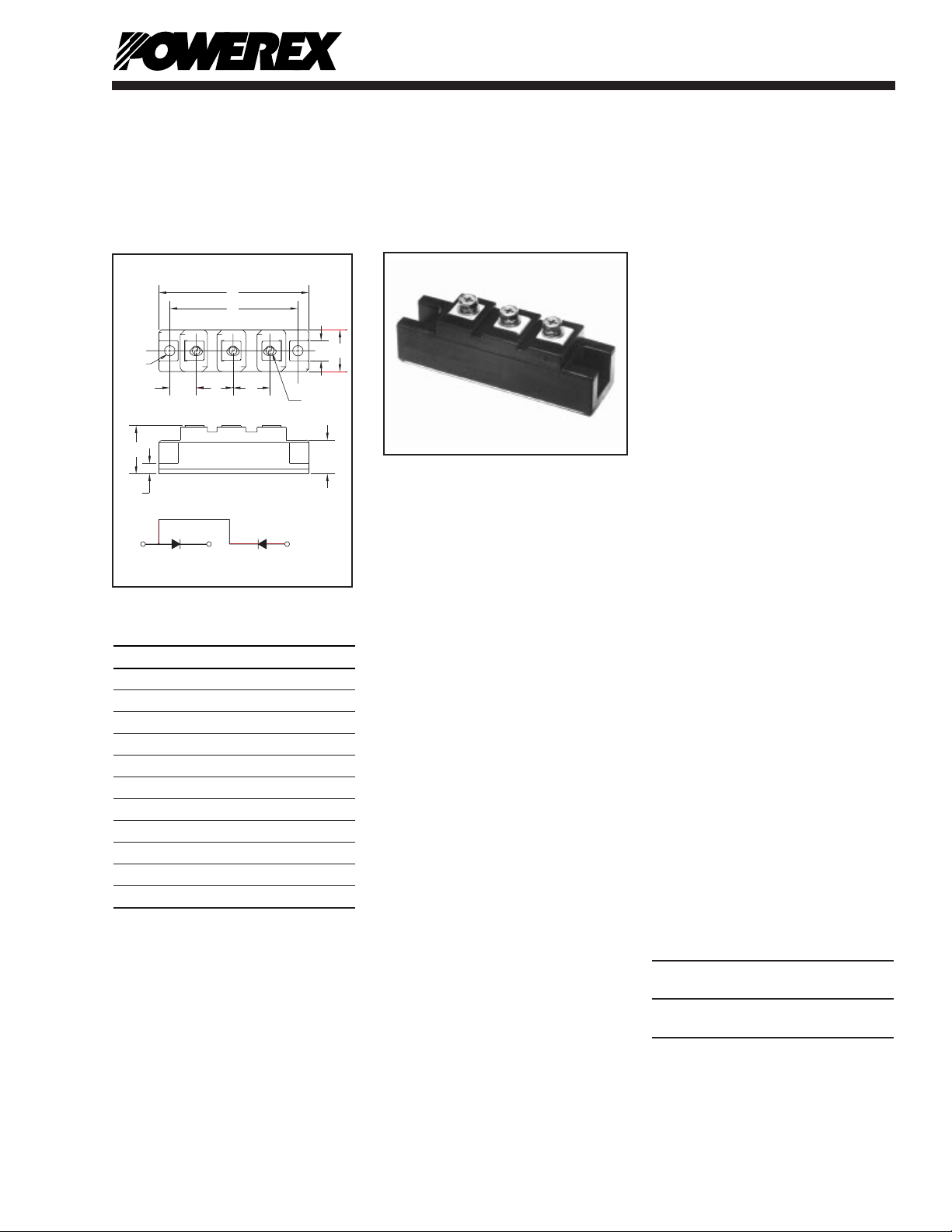
Dimension Inches Millimeters
A 3.681 Max. 93.5 Max.
B 3.150 80
C 1.181 Max. 30 Max.
D 1.024 Max. 26 Max.
E 0.827 21
F 0.906 23
G 0.650 16.5
H 0.512 13
J 0.256 6.5
K 0.256 Dia. Dia. 6.5
L M5 Metr ic M5
Description:
Powerex Dual Diode
POW-R-BLOK™ Modules are
designed for use in applications
requiring AC to DC rectification in
isolated packaging.The modules
are isolated for easy mounting
with other components on common heatsinks. POW-R-BLOK™
has been tested and recognized
by Underwriters Laboratories
(QQQX2 Power Switching
Semiconductors).
Features:
M Isolated Mounting
M Glass Passivated Chips
M Metal Baseplate
M Low Thermal Impedance
M UL Recognized A
Applications:
M Battery Supplies
M AC and DC Motor Power
Supplies
Ordering Information:
Select the complete eight digit
module part number you desire
from the table below.
Example: CD411260 is a
1200 Volt, 60 Ampere Dual Diode
POW-R-BLOK™ Module.
Voltage Current Rating
Type Volts (x100) Amperes (60)
CD41 12 60
16
D-107
Powerex,Inc., 200 Hillis Street,Youngwood, Pennsylvania 15697-1800 (724) 925-7272
Dual Diode
POW-R-BLOK™ Modules
60 Amperes/1200-1600 Volts
CD411260
CD411660
Outline Drawing
CD411260, CD411660
Dual Diode
POW-R-BLOK™ Modules
60 Amperes/1200-1600 Volts
A
F
C
J
E
E
G
D
H
A
B
(2 TYP.)
K - DIA.
(3 TYP.)
L - M5 THD
1
2
3
2
1
3
Page 2

D-108
Powerex,Inc., 200 Hillis Street, Youngwood, Pennsylvania 15697-1800 (724) 925-7272
CD411260, CD411660
Dual Diode POW-R-BLOK™ Modules
60 Amperes/1200-1600 Volts
Absolute Maximum Ratings
Characteristics Symbol CD411260 CD411660 Units
Peak Reverse Blocking Voltage V
RRM
1200 1600 Volts
Transient Peak Reverse Blocking Voltage (Non-Repetitive), t < 5ms V
RSM
1350 1700 Volts
DC Reverse Blocking Voltage V
R(DC)
960 1280 Volts
RMS On-State Current I
F(RMS)
95 95 Amperes
Average On-State Current, TC= 87°C I
F(AV)
60 60 Amperes
Peak One-Cycle Surge (Non-Repetitive) On-State Current (60Hz) I
FSM
1200 1200 Amperes
Peak One-Cycle Surge (Non-Repetitive) On-State Current (50Hz) I
FSM
1095 1095 Amperes
I2t (for Fusing), 8.3 milliseconds I2t 6000 6000 A2sec
Storage Temperature T
STG
-40 to 125 -40 to 125 °C
Operating Temperature T
j
-40 to 125 -40 to 125 °C
Maximum Mounting Torque M6 Mounting Screw — 26 26 in.-lb.
Maximum Mounting Torque M5 Terminal Screw — 17 17 in.-lb.
Module Weight (Typical) — 160 160 Grams
V Isolation V
RMS
2500 2500 Volts
Page 3

D-109
Powerex,Inc., 200 Hillis Street, Youngwood, Pennsylvania 15697-1800 (724) 925-7272
CD411260, CD411660
Dual Diode POW-R-BLOK™ Modules
60 Amperes/1200-1600 Volts
Electrical and Thermal Characteristics, Tj= 25°C unless otherwise specified
Characteristics Symbol Test Conditions CD411260/CD411660 Units
Blocking State Maximums
Reverse Leakage Current, Peak I
RRM
Tj= 125°C, V
RRM
= Rated 15 mA
Conducting State Maximums
Peak On-State Voltage V
FM
IFM= 180A 1.35 Volts
Thermal Maximums
Thermal Resistance, Junction-to-Case R
u(J-C)
Per Module 0.5 °C/Watt
Thermal Resistance, Case-to-Sink (Lubricated) R
u(C-S)
Per Module 0.2 °C/Watt
Page 4

D-110
Powerex,Inc., 200 Hillis Street, Youngwood, Pennsylvania 15697-1800 (724) 925-7272
CD411260, CD411660
Dual Diode POW-R-BLOK™ Modules
60 Amperes/1200-1600 Volts
INSTANTANEOUS ON-STATE CURRENT, IFM,
(AMPERES)
MAXIMUM
ON-STATE CHARACTERISTICS
10
0
10
1
10
2
10
3
Tj = 25oC
INSTANTANEOUS ON-STATE VOLTAGE, V
FM
, (VOLTS)
0.6
1.0
1.4
1.8
2.2
CYCLES AT 60 HZ
MAXIMUM PEAK SURGE (NON-REPETITIVE)
CURRENT, I
FSM
, (AMPERES)
MAXIMUM ALLOWABLE PEAK SURGE
(NON-REPETITIVE) CURRENT
10
0
10
1
10
2
0
400
800
1200
1600
2000
MAXIMUM
ALLOWABLE CASE TEMPERATURE
AVERAGE ON-STATE CURRENT, I
F(AV)
,
(AMPERES)
MAXIMUM ALLOWABLE CASE TEMPERATURE, T
C
, (
o
C)
06040 100
30
50
70
90
110
130
20 80
RESISTIVE
INDUCTIVE
LOAD
DC
SINGLE-PHASE
THREE-PHASE
OPERATION
MAXIMUM
ON-STATE POWER DISSIPATION
AVERAGE ON-STATE CURRENT, I
F(AV)
,
(AMPERES)
06040 100
0
20 80
MAXIMUM POWER DISSIPATION, P
AV(MAX)
, (WATTS)
40
80
120
160
RESISTIVE
INDUCTIVE
LOAD
DC
SINGLE-PHASE
THREE-PHASE
OPERATION
TIME, t, (SECONDS)
TRANSIENT THERMAL IMPEDANCE
CHARACTERISTICS (JUNCTION-TO-CASE)
0
0.10
0.20
0.30
0.40
0.50
TRANSIENT THERMAL IMPEDANCE, Z
u(J-C)
(t), (
o
C/WATT)
10
0
10
1
10
-3
10
-2
10
-1
10
0
 Loading...