

Page 1
Powerex, Inc., Hillis Street, Youngwood, Pennsylvania 15697 (724) 925-7272 POW-R-BLOK
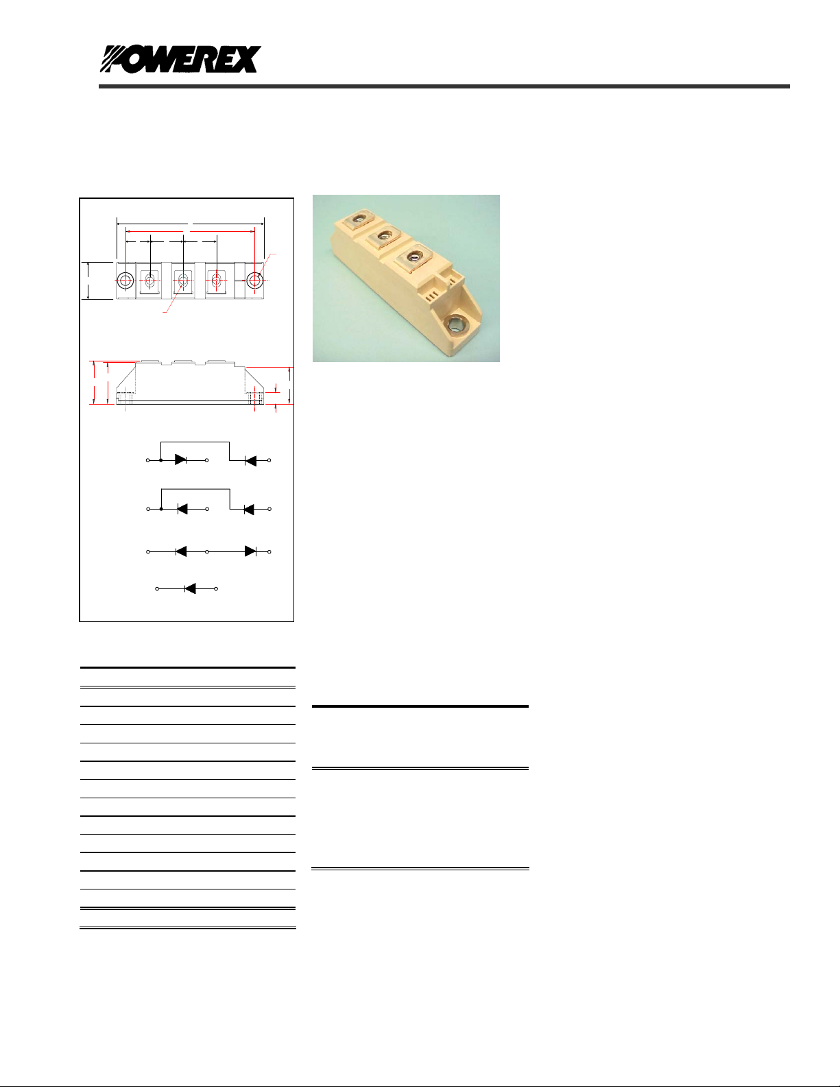
Dual & Single Diode Isolated Module
100 Amperes / Up to 1800 Volts
B
D
CD41
CC41
CN41
CS41
Outline Dimensions
Dimension Inches Millimeters
OUTLINE DRAWING
"U" THREAD
M
~
1
1
1
CONNECTION DIAGRAMS
A 3.66 93
B 0.79 20
C 3.15 80
D 1.18 30
F 0.61 15.5
G 0.79 20
H 0.79 20
M 1.16 29.4
N 0.31 8
P 0.94 24
T 0.25 6.4
U M5 M5
Note: Dimensions are for reference only.
A
C
G HF
3
2
1
+
2
+
+
+
2
--
2
-
2
-
T
CD41__99B, CS41__99B
P
CN41__99B, CC41__99B
N
Dual & Single Diode Isolated
POW-R-BLOKTM Module
100 Amperes / Up to 1800 Volts
-
3
3
+
3
3
Ordering Information:
Select the complete nine digit module
part number from the table below.
Example: CD411699B is a 1600 Volt,
100 Ampere Dual Diode Isolated
POW-R-BLOK
TM
Module
Current
Amperes
99
(100 A)
Version
Type
CD41
CC41
CN41
CS41
Voltage
Volts
(x100)
08
12
14
16
18
CD41__99B, CS41__99B
CN41__99B, CC41__99B
TM
Description:
Powerex Dual Diode & Single Diode
Modules are designed for use in
applications requiring rectification and
isolated packaging. The modules are
isolated for easy mounting with other
components on a common heatsink.
POW-R-BLOK
recognized by the Underwriters
Laboratories.
Features:
Electrically Isolated Heatsinking
DBC Alumina (Al
Copper Baseplate
Low Thermal Impedance
for Improved Current Capability
Benefits:
No Additional Insulation
Components Required
Easy Installation
No Clamping Components
Required
Reduce Engineering Time
Applications:
Power Supplies
Bridge Circuits
AC & DC Motor Drives
Battery Supplies
Large IGBT Circuit Front Ends
B
Lighting Control
Heat & Temperature Control
Welders
TM
has been tested and
) Insulator
2O3
Revision Date: 02/17/2005
Page 2

Powerex, Inc., Hillis Street, Youngwood, Pennsylvania 15697 (724) 925-7272 POW-R-BLOK
Dual & Single Diode Isolated Module
100 Amperes / Up to 1800 Volts
Absolute Maximum Ratings
Characteristics Conditions Symbol Units
Repetitive Peak Reverse Blocking Voltage V
Non-Repetitive Peak Reverse Blocking Voltage
(t < 5 msec)
RMS Forward Current DC Conduction, TC=90°C I
Average Forward Current 180° Conduction, TC=100°C I
Peak One Cycle Surge Current, Non-Repetitive 60 Hz, 100% V
I2t for Fusing for One Cycle 8.3 ms, 100% V
Operating Temperature TJ -40 to +150 °C
Storage Temperature T
Max. Mounting Torque, M6 Mounting Screw on
Terminals
Max. Mounting Torque, Module to Heatsink 44
Module Weight, Typical 95 g
3.35 Oz
V Isolation @ 25C
Circuit To Base, All Terminals Shorted Together
V
reapplied, TJ = 150°C
60 Hz, No V
50 Hz, 100% V
50 Hz, No V
8.3 ms, No V
10 ms, 100% V
10 ms, No V
RRM
reapplied, TJ = 150°C
RRM
reapplied, TJ = 150°C
RRM
reapplied, TJ = 150°C
RRM
reapplied, TJ = 150°C
RRM
reapplied, TJ = 150°C
RRM
reapplied, TJ = 150°C
RRM
reapplied, TJ = 150°C
RRM
25
50-60 Hz, 1 second
CD41__99B, CS41__99B
CN41__99B, CC41__99B
TM
up to 1800 V
RRM
V
RSM
157 A
F(RMS)
100 A
F(AV)
I
FSM
I
FSM
I
FSM
I
FSM
2
I
t
2
I
t
2
I
t
2
I
t
-40 to +150 °C
stg
V
rms
+ 100 V
RRM
1,780
2,110
1,700
2,020
13,190
18,650
14,450
20,430
3
5
3500 V
A
A
A
A
2
A
sec
2
A
sec
2
A
sec
2
A
sec
in. – Lb.
Nm
in. – Lb.
Nm
Revision Date: 02/17/2005
Page 3

Powerex, Inc., Hillis Street, Youngwood, Pennsylvania 15697 (724) 925-7272 POW-R-BLOK
Dual & Single Diode Isolated Module
100 Amperes / Up to 1800 Volts
Electrical Characteristics, TJ=25°C unless otherwise specified
Characteristics Symbol Test Conditions Min. Max.
Repetitive Peak Reverse Leakage Current I
Peak On-State Voltage VFM
Threshold Voltage, Low-level
Slope Resistance, Low-level
Thermal Characteristics
Characteristics Symbol
Thermal Resistance, Junction to Case
Thermal Resistance, Case to Sink Lubricated
Up to 1800V, TJ=150°C 10 mA
RRM
T
=25°C, IFM=300A, 180° Conduction
J
V
R
R
(FO)1
r
T1
ΘJ-C
ΘC-S
= 150°C, I = 16.7% x πI
T
J
Per Module, both conducting
Per Junction, both conducting
Per Module 0.1 °C/W
CD41__99B, CS41__99B
CN41__99B, CC41__99B
TM
1.35 V
F(AV)
to πI
F(AV)
0.85
Max. Units
0.175
Revision Date: 02/17/2005
1.3
0.35
Units
V
mΩ
°C/W
°C/W
Page 4

Powerex, Inc., Hillis Street, Youngwood, Pennsylvania 15697 (724) 925-7272 POW-R-BLOK
Dual & Single Diode Isolated Module
100 Amperes / Up to 1800 Volts
3
2.5
2
1.5
1
On-State Voltage - Vfm - Volts
0.5
0
10 100 1000
Maximum On-State Forward Voltage Drop
Instantaneous On-State Current - Ifm - Amperes
( Tj = 150 °C )
0.40
0.35
0.30
0.25
0.20
0.15
0.10
Thermal Impedance - Rjc - °C/W
0.05
0.00
0.001 0.01 0.1 1 10 100
CD41__99B, CS41__99B
CN41__99B, CC41__99B
TM
Maximum Transient Thermal Impedance
(Junction to Case)
Time - t - Seconds
Maximum On-State Power Dissipation
130
120
110
100
90
80
70
60
50
40
30
Max. Power Dissipation Per Diode - Watts
20
10
0
0 102030405060708090100
180
160
140
120
100
80
60
40
Max. Power Dissipation Per Diode - Watts
20
0
0 20406080100120140160
(Sinusoidal Wavefo rm)
90°
60°
30°
0
CONDUCTION ANGLE
Average On-State Current - If(av) - Amperes
Maximum On-State Power Dissipation
(Rectangular Waveform)
180°
120°
90°
60°
30°
0
CONDUCTION ANGLE
Average On-State Current - If(av) - Amperes
120°
180°
180
360
360°
270°
180
360
Maximum Allowable Case Temperature
150
145
140
135
130
125
120
115
110
Max. Case Temperature - Tcase -°C
105
100
0 102030405060708090100
(Sinusoidal Waveform)
0
CONDUCTION ANGLE
30°
Average On-State Current - If(av) - Amperes
60°
90°
180
360
180°
120°
Maximum Allowable Case Temperature
(Rectangular Waveform)
150
145
140
135
130
125
120
115
110
105
Max. Case Temperature - Tcase -°C
100
95
90
0 20 40 60 80 100 120 140 160
30°
60°
90°
120°
180
0
CONDUCTION ANGLE
180°
270°
360
Average On-State Current - If(av) - Amperes
360°
Revision Date: 02/17/2005
 Loading...