

Page 1
C781
Powerex, Inc., 200 Hillis Street, Youngwood, Pennsylvania 15697-1800 (412) 925-7272 Phase
Powerex, Europe, S.A. 428 Avenue
G.
Durand, BP107, 72003
Le
Mans, France (43) 41.14.14 2500 Amperes Average
2100 Volts
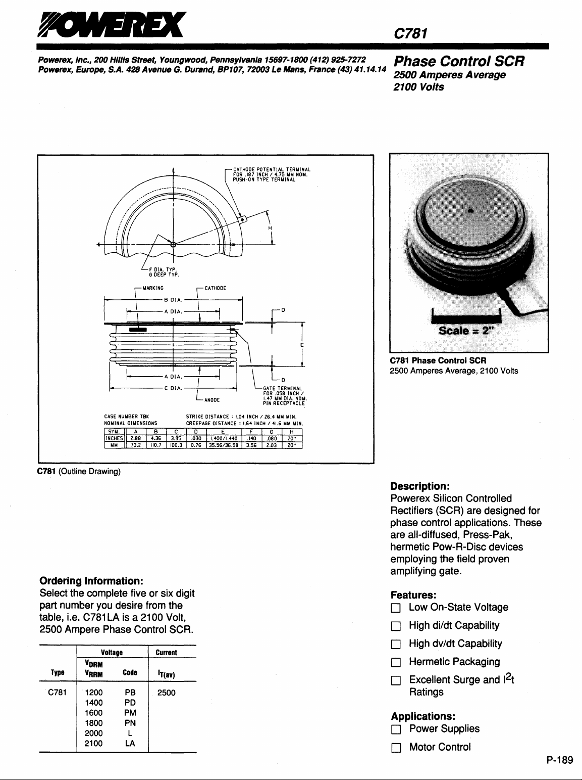
CATHOOE
POTENTIAL
INCH / 4.7S
TYPE
TERMINAL
TERMINAL
MM
NOM.
r
CATHODE
FOR
.187
PUSH·ON
Control
SCR
I~AOIA.~I
~CDIA·~L
CASE
NUMBER
NOMINAL
C781 (Outline Drawing)
Ordering Information:
Selectthe
part number you desire from the
table, i.e.
2500
Type
C781
complete five or six digit
C781
LA is a 2100 Volt,
Ampere Phase Control SCR.
Voltage
VORM
VRRM
1200
1400
1600
1800
2000
2100
TBK
DIMENSIONS
Code
PB
PO
PM
PN
L
LA
Current
If(av)
2500
ANODE
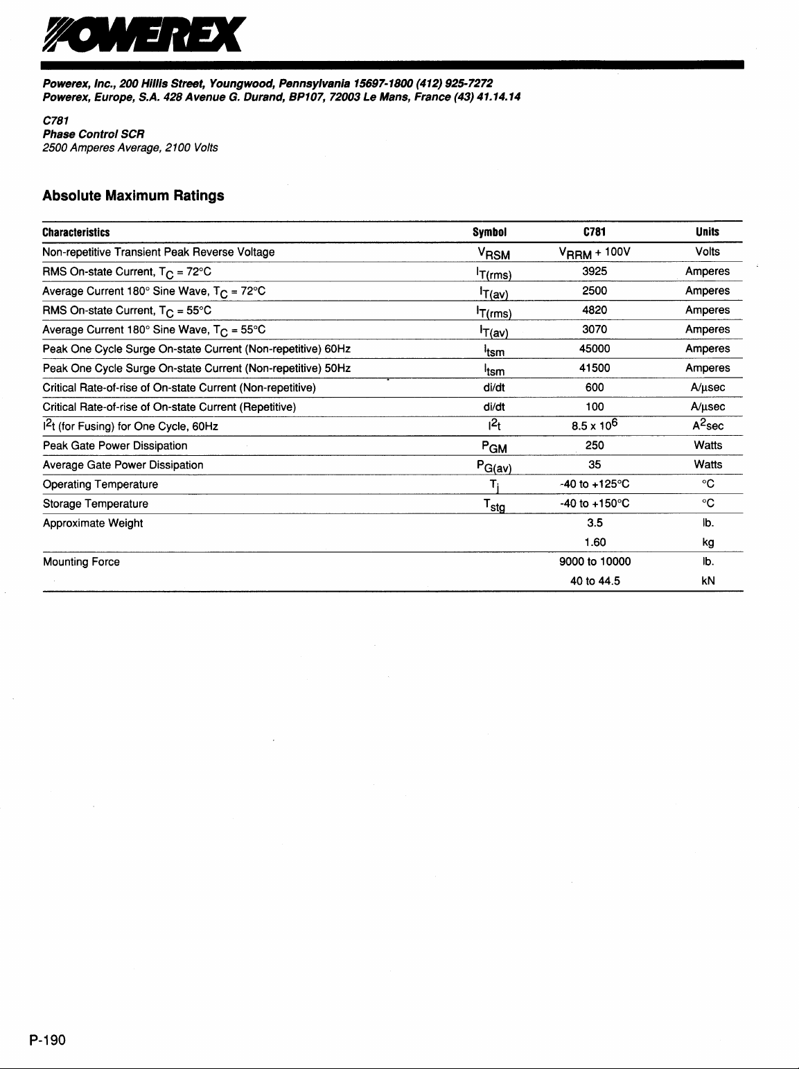
C781
Phase
Control
2500
Amperes Average, 2100 Volts
SCR
Description:
Powerex Silicon Controlled
Rectifiers (SCR) are designed for
phase
are
control applications. These
all-diffused, Press-Pak,
hermetic Pow-R-Disc devices
employing the field proven
amplifying gate.
Features:
D Low On-State Voltage
D High di/dt Capability
D High dv/dt Capability
D Hermetic Packaging
2
D Excellent Surge and 1
t
Ratings
Applications:
D Power Supplies
D Motor Control
P-189
Page 2
Powerex, Inc., 200 Hillis Street, Youngwood, Pennsylvania 15697-1800 (412) 925-7272
Powerex, Europe, S.A. 428 Avenue
G.
Durand, BP107, 72003 Le Mans, France (43) 41.14.14
C781
Phase
Control
2500 Amperes Average,
SCR
2100
Volts
Absolute Maximum Ratings
Characteristics
Non-repetitive Transient Peak Reverse Voltage
RMS On-state Current, T C = 72°C
Average Current 180° Sine Wave, T C = 72°C
RMS On-state Current, T C = 55°C
Average Current 180° Sine Wave, T C = 55°C
Peak One Cycle Surge On-state Current (Non-repetitive) 60Hz
Peak One Cycle Surge On-state Current (Non-repetitive) 50Hz I
Critical
Rate-of-rise of On-state Current (Non-repetitive) di/dt
Critical Rate-of-rise of On-state Current (Repetitive)
2
1
(for Fusing) for One Cycle, 60Hz
t
Peak Gate Power Dissipation
Average Gate Power Dissipation
Operating Temperature
Storage Temperature
Approximate Weight
Mounting Force
Symbol
VRSM
IT(rms)
IT(av)
IT(rms)
IT(av)
I
tsm
t5m
di/dt
2
1
t
PGM
PG(av)
Tj
T
stg
C781
VRRM + 100V
3925
2500
4820
3070
45000
41500 Amperes
600
100
6
8.5 x 10
250
35
-40 to + 125°C °C
-40 to + 150°C
3.5 lb.
1.60
9000 to 10000
40
to 44.5 kN
Units
Volts
Amperes
Amperes
Amperes
Amperes
Amperes
Aillsec
Aillsec
A2sec
Watts
Watts
°C
kg
lb.
P-190
Page 3

Powerex, Inc., 200 Hillis Street, Youngwood, Pennsylvania 15697-1800 (412) 925-7272
Powerex, Europe, S.A.
428
Avenue
G.
Durand, BP107, 72003 Le Mans, France (43) 41.14.14
C781
Phase Control SCR
2500 Amperes Average, 2100 Volts
Electrical Characteristics, Tj = 25°C Unless Otherwise Specified
Characteristics
Repetitive Peak Reverse Leakage Current
Repetitive Peak Forward Leakage Current
Peak On-state Voltage
Threshold Voltage, Low-level
Slope Resistance, Low-level
Threshold Voltage, High-level
Slope Resistance, High-level
VTM Coefficients,
VTM Coefficients, High-level
Typical Delay
Typical Turn-off Time
Minimum
Gate Trigger Current
Gate Trigger Voltage
Non-Triggering Gate Voltage
Peak Forward Gate Current
Peak Reverse Gate
Critical dv/dt - Exponential to VDRM
Low-level
Time
Voltage
Symbol
IRRM
IDRM
VTM
V(TO) 1
rT1
V(TO)2
rT2
dv/dt
Test
Conditions
Tj = 125°C, VR = VRRM
Tj
= 125°C, VD = VDRM
= 125°C, IT = 2000A Peak
Tj
Duty
Cycle < 0.1%
Tj = 125°C, I = 15%, IT(av) to 1tIT(av)
Tj = 125°C, I = 1tIT(av) to ITSM
Tj = 125°C, I = 15% IT(av) to 1tIT(av)
Tj = 125°C, IT = 2000A,
tp > 3msec,diR/dt = 5A1llsec,
V Reapplied = 1000V,
dv/dt = 1
OOOV
/Ilsec, V R = 100V
Min.
500
Typ.
A1
81
C1
D1
A2 = 30.510
82
C2
D2 = 0.1610
3
250
Max.
150 rnA
150
1.20
0.94963 Volts
0.1234
1.1007
0.1149
Units
mA
Volts
m!l
Volts
mQ
= -0.007132
= 0.18721
= 1.589E-04
= -0.011393
= -4.6029
= -2.083E-04
sec
Il
sec
Il
sec
V/Il
250
4.2
0.5
20
20
rnA
Volts
Volts
A
Volts
Thermal Characteristics
Maximum Thermal Resistance, Double Sided Cooling
Junction-to-Case
Case-to-Sink
Re(j-c)
Re(C-s)
0.012
0.002
P-191
Page 4

Powerex, Inc., 200 HIllis Street, Youngwood, Pennsylvania 15697-1800 (412) 925-7272
Powerex, Europe, S.A.
C781
Phase
ControiSCR
1500 Amperes Average, 2400 Volts
428
Avenue
G.
Durand, BP107, 72003
Le
Mans, France (43) 41.14.14
Maximum On-State Forward Voltage Drop
5
~
4
!
3
I
&
2
I
I
o
o
10
5000
.----.,...----r---~--~--~--..,
C
~
~o
r-~=-+-----+-----~----~~~~----_i
IS
13000
1-----+--+--7'--t~~4----------.,f___-_i
I
Q
1
1-----+---~~~---I+---+---+-----1
2000
Jj
E
1~r-----~~~+-----~-O-=~==~=C-----i
100
Instantaneous On-8tate Current - Itm - Amperes
Maximum On-State Power Dissipation
I
o~----~----~----~----------~----~
o
500
Average On-State Current - It(av) - Amperes
(Tj
= 125
°C)
i-"'i-"
~
--
1000
(Sinusoidal Waveform)
1000 1500
2000
V
10000
/
2500
0.0125
/
I
~
0.01
~
e
0.0075
I
.5
0.005
~
!
0.0025
130
~
120
110
1
~
~
100
~
90
B.
80
E
{!
70
~
60
I
50
40
o
0.001
100000
3000
Maximum Transient Thermal Impedance
(Junction
to
Case)
~
I
J
/
.---/
0.01
Maximum Allowable Case Temperature
r---.
~
~
~
§!]
o
500
Average On-8tate Current - It(av) - Amperes
0.1
Time - t - Seconds
(Sinusoidal Waveform)
~
~~
~
~~
""
1000 1500
VV
/
V
I
(,
11iO
PNDUCTlON
-c
~
-:IV
1'120~
2000
(\
10
,
~LE
Ian·
2500
100
380
3000
P-192
Maximum On-State Power Dissipation
6000
(Rectangular Waveform)
§]
15000
1-
03000
12000
Jj
i
1000
0
0
Note: Spreading losses included. Curves are for an inductive load.
1000 1500
500
Average On-State Current - It(av) - Amperes
2000
2500
3000
3500
~
4500
130
~
120
1
110
~
!
100
:::J
!
B.
~
•
c!
tIi
:IE
90
80
70
60
50
Maximum Allowable Case Temperature
(Rectangular Waveform)
~
~~
~
~
~
~
"'~
§!]
o
500
1000 1500
Average On-$tate Current
f::0..
\~
~~
uu
"
~~1-;C
2000 2500
~
~""
-It(av)
r-l
I I
rr~
uCON
PUCTlON
~
"18
I~~
3000 3500
- Amperes
80
ANGLE
~
"-
4000
380
60·
4500
 Loading...