

Page 1
INVERTER THYRISTOR
C770L
C770PN
C770PS
C770PM
C770PE
C770PD
2000 Volts
1800
1700
1600
1500
1400
GE-SPCO
The GE type C770 reverse blocking thyristor is suitable for inverter applications.Thesilicon
is
junction
involute gate structure.
using commercially available heat dissipators and mechanical clamping hardware.
10000
1000
100
manufactured
On-state
-
o
current
/
e770
77mm / 1800V / 100us
Disc-type ceramic PRESSPAK package
by
the proven multi-diffusion process and utilizes the exclusive
It is supplied in an industry accepted disc-type package, ready to mount
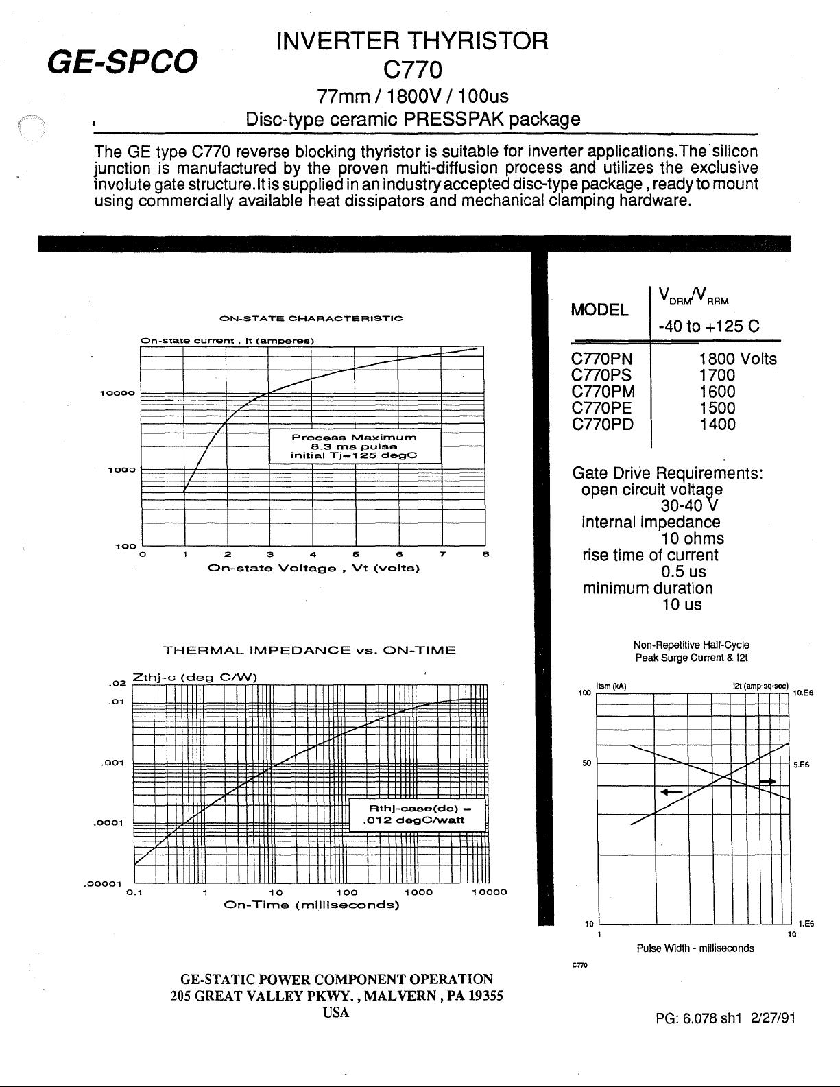
ON-STATE
It
CHARACTERISTIC
(amperes)
-
I.--'"
--
---
/
/
:2
On-state
Process
initial
3 4
Voltage.
B.3
Maximum
IT'IS
puis
Tj_1
2S
degC
6 e 7
Vt
(volts)
..
e
MODEL
VDRJVRRM
-40 to +125 C
C770PN
C770PS
C770PM
C770PE
C770PD
1800 Volts
1700
1600
1500
1400
Gate Drive Requirements:
open circuit voltage
30-40 V
internal impedance
10 ohms
rise time of current
0.5 us
minimum duration
10 us
.0001
.00001
.01
.001
.02
Zthj-c
V
0.1
THERMAL
./
205
IMPEDANCE
(deg
C/W)
V
/'
/'
On-Time
GE·STA TIC
10
(milliseconds)
POWER
COMPONENT OPERATION
GREAT VALLEY PKWY. ,
USA
V
II
100
vs.
ON-TIME
Rthj-ca.ae(dc)
.012
MAL
degClvvatt
1000
VERN,
-
10000
PA 19355
C770
100
Non·Repetitive
Peak
Surge
Ilsm
(kA)
-......
50
r--.
Hall-Cycle
Current & 121
121
-.....
V
J><
r--..
V
(am~sq-sec)
V
!-...
r--
10.ES
S.ES
V
./"
10
Pulse
WIdth -milliseconds
PG:
6.078
sh1
2127/91
10
1.E6
Page 2
GE-SPCO
up to
2000
e770
PARAMETER
Repetitive
state &
Off-state
leakage current
Average
current
Peak
non-rep surge current
On-state voltage
Critical
of on-state current
Critical
of
Recovery current
Turn-on
Turn-off
peak
off-
reverse
volts
&
reverse
on-state
half-cycfe
rate
of
rise
rate
of
off-state voltage
rise
delay
time
LIMITING
CHARACTERISTICS
SYMBOL CONDITION
V
ORM
V
RRM
IOAt.!
IRRM
IT\AV)
~
VTt.\
dVdt
rep
dv/dt T
I
At.!
td
T ..
TEST
Tr
to
TJ-
60Hz
so
40
125°C
125°C
To
...
-
70°C
Hz
IT=2000A
lp=8.3ms
TJ=125°C
TJ-125°C
60
Hz
c
125°C
J
Vo=80%V
TJ=125°C
25A1us
Vd=67%V
25
Alus,
reverse
400V/us-
AND
ORM
o
with
diode
67%VDRM
RATINGS
Rt.l
.l.I..MlI
up
to
1800
100
2100
38
35
1.55
300
500
200
2
~
V
rna
A
kA
V
Alus
V/us
A
us
us
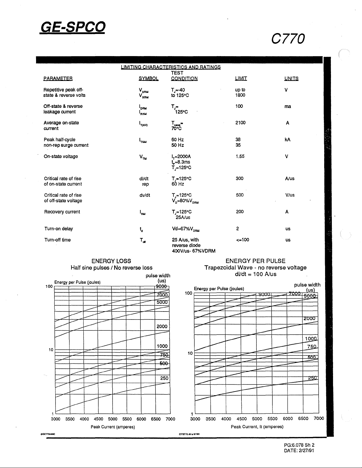
ENERGY LOSS
Half
sine
pulses / No reverse loss
pulse width
Energy per Pulse
100
~
L
V
~
~
10
.-
,........
~
V-
.....-
----
---
1 1
3000 3500 4000 4500 5000 5500 6000 6500 7000 3000
-----
V--
----
V
---
--
.----
----
~
V
l----"
Uoules)
I--""
---
--
-
:---
I-""
--
----
----
.---
-
:---
--
---
I--
Peak Current (amperes) Peak Current, It (amperes)
~
---
-
r--
-
I---
---
--
(us)
,..,..,
7(\(\(1
-
~UUU
--
-
--
2000
~
--
1000
--
~
-
---
'"
-'-
.,.,..,..
250
100
ENERGY PER PULSE
Trapezoidal Wave - no reverse voltage
Ene
--
---
V
10
------
--
~
--
rgy
per
----
r-
----
~
---
---
~
PI
usa
----
-~
--
V-
dildt = 100
(jou es)
-
--
r-
---
r-
.....-
......-
---
---
I---
Nus
I--"
I--"'
--
--
I---
-
--
3500
4000 4500
5000
5500 6000
-
--
--
--
--
r-
-
pulse width
(us)
-
~U~
~
~
-
~
PG:6.078
DATE:
2127/91
Sh
2
Page 3

GE-SPCO
The
foIortMg
stable thennaI and
the PRESSPAK to heat
1.
INSPECTION OF
ChecI<
"nlsh.The PRESSPAK
TIR
electrical test
surface
Iast8cl
not
wtth
based
.2. SURFACE DEOXIDATION
Although plated surfaces are recommended lor aluminum and
copper heat dlsslpators, bare surfaces may be used
careful attention to cleaning
Plated
wfth
recommended. Unplated surfaces should
abralded with a
coated with Alcoa
be
3.
FINAL SURFACE TREATMENT
Apply silicone
compound
property dlstrlbute the applied agent.
••
MOUNTING
Instruction
each mating surface for nicks, scratches and surface
< .0005 Inch and surface "nlsh prior
should
PRESSPAK may run higher
InclUding
the
last nxturas.(Recommended mounting loreels
upon these requirements.) " .002" lor
surfaces and PRESSPAKS should
600 grit paper, then
removed
I. naentlal for maintaining
eIect:tIcaI
In
be
some
nne
and
mlstances
clulpator
MATING
pressure nxturas. The dissipater
the recommended compound applied.
SURFACES
surface has a total Indicator reading
equally as good.The
minor nicks and scratches associated
AND
011
or compound applied as
wire brush or
EJC
#'2
compound. The Alcoa
011
or a
very
lUrlacea.
CLEANING
and
treating
3M
thin layer
auoc::lallld with
TIR
but
01
not
exceed .001" Inch
Is
assured.
be
be
"Scotchbrlte"
01
grease or
low,
a fully
lightly sanded
vigorously
#'2
as Indicated below. Rotate the PRESSPAK to
· bare copper - use G322L
· bare aluminum - use
· tin plated copper or aluminum - preferably use
SF1154. Alternatively use G623 or G322L
· nickel-plated aluminum -
• silver plating
Assemble
aell·leveilng swivel connection. The swivel plate
diameter should
the paleface diameter
the top
wtth
specified
be preferably equal but not smaller than
and bottom
NOTES:
Silicone
-slllcol'l81lrease
products of General Electric Co. EJC
compound
of
of
Umlt maximum joint temperature to 95 C,except
for those prepared with SF1154 or
can
Alcoa
Is
not recommended
01
Am
erIca.LS2037Is a black compound,a product
ARCO
bEt
use
mounting lorce applied through a
01
the PRESSPAK.
the PRESSPAK are
011
SF1154{200 centlstoke),cIear
Is
a product of the Aluminum Company
00.,7301 Bessemer Ave.,Cleveland,OH
used up
or
#'2
LS2037 •
or G322L
SF1154 or G623
Center
tor
G623
and yellow
to
1
50
C
locating.
G322L
If
should
holes on
are
~
G3221
to
factory
nmm.
Yt'hk:h
ellD
-'-----"_!
i
-"ERM,
I,
t
c
F,
•
TERM 4
PLATED SURFACE _
SYMBOL
0A
08
I
~
INCHES
MIN.
-
2.876 2.880
C 1.387 1.447
0
0E
F
.080
0.136
0.20
G 2.403 2.418 61.16
H
External
-
Clamping
8000 Ib minirrum
9000 Ib maxirrum
Anode·Cathode
Electrical Insulation, Glazed Ceramic, Creepage
(40.6mmJ. Strike 1.0 in. (25.4mm)
Gate Leads
with
#8
Pole Faces
00
Ring Terminal.
18
in.
,e
~
~8
MAX.
4.350
-
0.146
-
- -
Force:
00
#22
Terminated Nicke,
-I
;'e::iM-;J
MILL\1E-;-E~S
MIN.
-
73.05
35.23
2.03
3.4::
0.86
Nickel
Pla~ej
;
(DC"")
_,
, ~ \c=
I
i 1
!
,
i
I
I
,
I
T
1.6
OF
(op--\
~.1AX
;0 . .19
(3. ~ 5
36.75 '
-
,...
";;.1
-
6: . .12
-
':
P,,:eo
_"E/
:'j
I
,
I
-:"""
I
!
~ocer
~
PG:
6.078 sh3
3114190
 Loading...