

C702
r
Phase Control Thyristo
1000 Amperes 3200 Volts
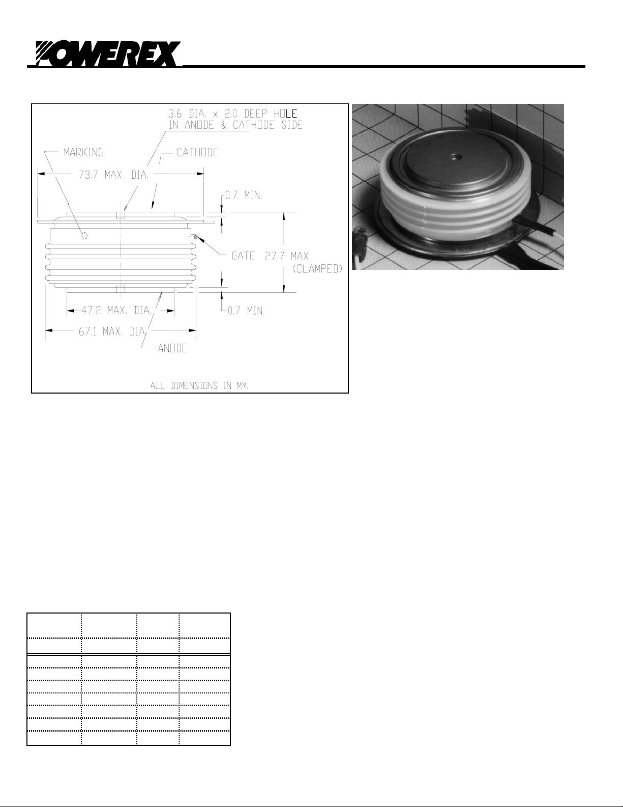
The C702 is a medium voltage, high
current disc pack SCR employing a Bar
gate, amplifying gate structure. This
amplifying gate design allows the SCR to
be reliably operated at high di/dt and
high dv/dt conditions in phase control
applications.
FEATURES:
Low On-State Voltage
High di/dt Capability
High dv/dt Capability
Hermetic Ceramic Package
Excellent Surge and I
APPLICATIONS:
DC Power Supplies
ORDERING INFORMATION Motor Controls
AC Soft-Starters
Select the complete Part Number using the table below.
EXAMPLE: C702CB is a 3200V-1000A SCR with 200ma
IGT and 12 inch gate and cathode potential leads.
Voltage
PART
C702 2400V LD 1000A
Rating
V
DRM-VRRM
2600V LM
2800V LN
3000V CP
3200V CB
Voltage
Code
Current
Rating
I
tavg
2
t Ratings
Revised: 5/11/2004
Page 1

r
Absolute Maximum Ratings
Characteristic Symbol Rating Units
C702
Phase Control Thyristo
1000 Amperes 3200 Volts
Repetitive Peak Voltage
Non-repetitive Transient Peak Reverse Voltage
Average On-State Current, T
RMS On-State Current, T
Average On-State Current, T
RMS On-State Current, T
Peak One Cycle Surge Current, 60Hz, V
Peak One Cycle Surge Current, 50Hz, V
Fuse Coordination I
Fuse Coordination I
=74°C
C
=74°C
C
=55°C
C
=55°C
C
=0V I
R
=0V I
R
2
t, 60Hz I2t
2
t, 50Hz I2t
V
DRM-VRRM
V
RSM
I
T(Avg.)
I
T(RMS)
I
T(Avg.)
I
T(RMS)
TSM
TSM
3200 Volts
V
+ 100
RRM
1000 A
1571 A
1220 A
1916 A
21,500 A
20,500 A
1.93E+06
2.10E+06
Volts
A2s
A2s
Critical Rate-of-Rise of On-State Current di/dt 100 A/us
Repetitive
Critical Rate-of-Rise of On-State Current di/dt 300 A/us
Non-Repetitive
Peak Gate Power, 100us
Average Gate Power
P
P
GM
G(avg)
16 Watts
5 Watts
Operating Temperature Tj -40 to+125 °C
Storage Temperature
T
Stg.
-50 to+150 °C
Approximate Weight 1 lb
0.45 Kg
Mounting Force 5500-6000 lbs
24.5 - 26.7 Knewtons
Page 2

C702
r
R
titi
R
titi
A
V
/
Phase Control Thyristo
1000 Amperes 3200 Volts
Electrical Characteristics, Tj=25°C unless otherwise specified
Rating
Characteristic Symbol Test Conditions min typ max Units
epe
ve Peak Forward
Leakage Current
epe
ve Peak Reverse
Leakage Current
Peak On-State Voltage
V
Model, Low Level V
TM
VTM = V
+ r•I
O
TM
I
DRM
I
RRM
V
Tj=125°C, V
Tj=125°C, V
Tj=125°C, ITM=2000
TM
Tj=125°C 0.944 V
0
15% I
r
TM
- π•I
DRM
RRM
TM
=Rated
=Rated
150 ma
150 ma
1.85 V
4.25E-04 Ω
VTM Model, High Level V
VTM Model,
V
TM
VTM = V
4-Term A Tj=125°C 0.363
= A + B•Ln(ITM) +
C•(I
O
) + D•(ITM)
TM
+ r•I
TM
½
Tj=125°C 1.18 V
0
r
B
π•I
15%ITM - I
TM
- I
TSM
TSM
3.49E-04 Ω
0.108
C 3.42E-04
D -8.33E-04
VD = 0.5•V
Turn-On Delay Time
t
d
DRM
2.5 us
Gate Drive: 40V - 20Ω
Turn-Off Time tq Tj=125°C 400 us
dv/dt
(Crit)
Gate Trigger Current
Gate Trigger Voltage
Peak Reverse Gate Voltage
dv/dt = 20V/us to 80%
dv/dt Tj=125°C Exp. Waveform 400 V/us
V
=80% Rated
D
Tj=25°C VD = 12V
GT
GT
V
I
V
GRM
DRM
30 100 200 ma
0.8 2.0 4.5 V
5V
Thermal Characteristics
Rating
Characteristic Symbol Test Conditions min typ max Units
Thermal Resistance
Junction to Case
Case to Sink
Thermal Impedance Model
ZΘjc(t) =
Σ(A(N)•(1-exp(-t
RΘ
RΘ
ZΘ
Double side cooled 0.021 0.023 °C/Watt
jc
Double side cooled 0.004 0.006 °C/Watt
cs
Double side cooled
jc
Tau(N))))
where: N = 123 4
A(N) = 7.26E-04 1.58E-03 4.55E-03 1.62E-02
Tau(N) = 4.49E-05 8.21E-03 8.84E-02 1.31E+00
Page 3
C702
r
Phase Control Thyristo
1000 Amperes 3200 Volts
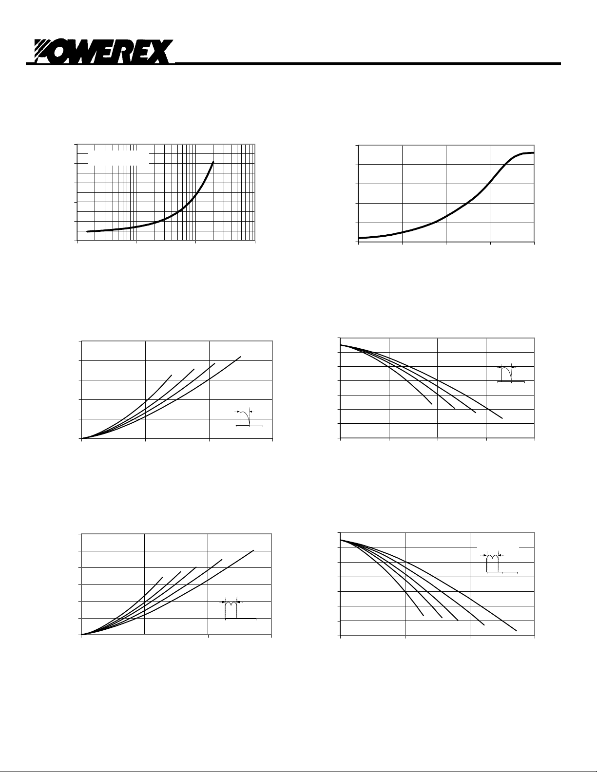
Maximum On-State Voltage Drop
10.0
Tj = 125°C
100 1000 10000 100000
ITM (A)
VTM (V)
8.0
6.0
4.0
2.0
0.0
Maximum On-State Power Dissipation
2500
2000
1500
1000
Pavg (Watts)
500
0
0 400 800 1200
Sinusoidal Waveform
60°
Iavg (A)
120° 180°
90°
CONDUCTION ANGLE
0° 180° 360°
2.5E-02
2.0E-02
1.5E-02
1.0E-02
(°C/Watt)
5.0E-03
Thermal Impedance
0.0E+00
130
120
110
100
90
Tc (°C)
80
70
60
MAXIMUM TRANSIENT THERMAL
IMPEDANCE
0.001 0.01 0.1 1 10
Time (sec)
Maximum Allowable Case Temperature
Sinusoidal Waveform
CONDUCTION ANGLE
0° 180° 360°
60°
90°
120°
0 300 600 900 1200
Iavg (A)
180°
Maximum On-State Power Dissipation
Square Waveform
3000
2500
2000
60°
°
120°
1500
1000
CONDUCTION ANGLE
Pavg (Watts)
500
0
0 500 1000 1500
Iavg (A)
180°
0° 180° 360°
360°
Page 4
Maximum Allowable Case Temperature
Square Waveform
130
120
110
100
90
Tc (°C)
80
70
60°
90°
60
0 500 1000 1500
Iavg (A)
CONDUCTION ANGLE
120°
0° 180° 360°
180°
360°
 Loading...