

Page 1

MEDIUM VOLTAGE SOFTSTARTER
Getting Started Manual
Page 2

Page 3

medium voltage soft starter
Getting Started Manual
Edition: November 2008
VS65IM01AI Rev. A
Page 4

VS65
POWER ELECTRONICS
2
Page 5
POWER ELECTRONICS
SAFETY SYMBOLS
Always follow safety instructions to prevent accidents and potential hazards from occurring.
VS65
WARNING
CAUTION
This symbol means improper operation may results in serious personal
injury or death.
Identifies shock hazards under certain conditions. Particular attention should
be given because dangerous voltage may be present. Maintenance
operation should be done by qualified personnel
Identifies potential hazards under certain conditions. Read the message and
follow the instructions carefully.
Identifies shock hazards under certain conditions. Particular attention should
be given because dangerous voltage may be present.
Edition of November 2008
This publication could present technical imprecision or misprints. The information here included will be
periodically modified and updated, and all those modifications will be incorporated in later editions.
To consult the most updated information of this product you might access through our website
www.power-electronics.com where the latest version of this manual can be downloaded.
3
Page 6

VS65
Revisions
Date Revision Description
30 / 11 / 2008 A First edition
POWER ELECTRONICS
4
Page 7

POWER ELECTRONICS
INDEX
SAFETY INSTRUCTIONS........................................................................................................... 7
1. INTRODUCTION.................................................................................................................. 11
1.1. Overview .................................................................................................................... 11
1.2. Technical Indicators and Performance....................................................................... 11
1.3. Design Features......................................................................................................... 12
1.4. Operating Principle..................................................................................................... 13
1.5. Protection for Motor and System................................................................................ 14
2. INSTALLATION AND CONNECTION.................................................................................. 16
2.1. Acceptance and Unpacking ....................................................................................... 16
2.2. Initial Inspection ......................................................................................................... 16
2.3. Operating Environment .............................................................................................. 16
2.4. Power Connections.................................................................................................... 16
2.5. Control Terminals Description.................................................................................... 17
2.6. Connection and Usage of Control Terminals ............................................................. 18
3. STANDARD RATINGS ........................................................................................................ 20
3.1. Designation Code....................................................................................................... 20
3.2. Table of Standard Ratings ......................................................................................... 21
VS65
4. PROGRAMMING KEYBOARD............................................................................................ 22
4.1. Display and Keyboard................................................................................................ 22
4.2. Function Code Table and Description ........................................................................ 22
4.3. Function Codes Explanations .................................................................................... 23
4.4. How to Program ......................................................................................................... 28
5. POWERING ON AND RUNNING......................................................................................... 30
5.1. Low-Voltage Trial Run................................................................................................ 30
5.2. High-Voltage Trial Run............................................................................................... 31
5.3. Data Display in Running............................................................................................. 31
6. FAULT MESSAGES. DESCRIPTIONS AND ACTIONS...................................................... 32
6.1. Fault Code Table........................................................................................................ 32
6.2. Fault History............................................................................................................... 33
7. COMMUNICATION PROTOCOL......................................................................................... 34
7.1. Profibus Protocol........................................................................................................
7.2. Modbus Protocol ........................................................................................................ 38
8. ANNEXE A. POWER CABINET OPERATION..................................................................... 41
8.1. Switch Operation of Power Cabinet ........................................................................... 42
8.2. Control Panel of Power Cabinet................................................................................. 42
9. ANNEXE B. ELECTRICAL AND MECHANICAL DRAWINGS............................................ 54
34
INDEX
5
Page 8

VS65
POWER ELECTRONICS
6
INDEX
Page 9
POWER ELECTRONICS
SAFETY INSTRUCTIONS
IMPORTANT!
Read this manual carefully to maximise the performance of this product and to ensure its safe
use.
In this manual, safety messages are classified as follows:
WARNING
VS65
Do not remove the cover while the power is applied or the unit is in operation.
Otherwise electric shock could occur.
Do not run the softstarter with the front cover removed.
Otherwise you may get an electric shock due to the high voltage terminals or exposure of
charged capacitors.
Do not remove the cover except for periodic inspections or wiring, even if the
input power is not applied.
Otherwise you may access the charged circuits and get an electric shock.
Operate the switches with dry hands.
Otherwise you may get an electric shock.
Do not use cables with damaged insulation.
Otherwise you may get an electric shock.
Do not subject the cables to abrasions, excessive stress, heavy loads or pinching.
Otherwise, you may get an electric shock.
CAUTION
Install the softstarter on a non-flammable surface. Do not place flammable material
nearby.
Otherwise fire could occur.
Disconnect the input power if the softstarter gets damaged.
Otherwise it could result in a secondary accident or fire.
Do not apply power to a damaged softstarter or to a softstarter with parts missing
even if the installation is complete.
Otherwise you may get an electric shock.
Do not allow lint, paper, wood chips, dust, metallic chips or other foreign matter
into the softstarter.
Otherwise fire or accident could occur.
SAFETY INSTRUCTIONS
7
Page 10

VS65
POWER ELECTRONICS
WARNINGS
RECEPTION
The VS65 softstarters are carefully tested and perfectly packed before leaving
the factory.
In the even of transport damage, please ensure that you notify the transport
agency and POWER ELECTRONICS: 902 40 20 70 (International +34 96 136
65 57) or your nearest agent, within 24hrs from receipt of the goods.
UNPACKING
Make sure model and serial number of the variable speed drive are the same
on the box, delivery note and unit.
Each softstarter is supplied with a technical manual.
RECYCLING
Packing of the equipments should be recycled. For this, it is necessary to
separate different materials included (plastic, paper, cardboard, wood, ...) and
deposit them on proper banks.
Waste products of electric and electronic devices should be selectively
collected for their correct environmental management.
SAFETY
Before operating the softstarter, read this manual thoroughly to gain and
understanding of the unit. If any doubt exists then please contact POWER
ELECTRONICS, (902 40 20 70 / +34 96 136 65 57) or your nearest agent.
Wear safety glasses when operating the equipment with power applied and the
front cover is removed.
Handle the softstarter with care according to its weight.
Do not place heavy objects on the softstarter.
Ensure that the mounting orientation is correct.
Do not drop the softstarter or subject it to impact.
The VS65 softstarters contain static sensitive printed circuits boards. Use static
safety procedures when handling these boards.
Avoid installing the softstarter in conditions that differ from those described in
the Technical Characteristics section.
8
SAFETY INSTRUCTIONS
Page 11

POWER ELECTRONICS
VS65
PRECAUTIONS
Electric shock prevention:
The enclosure of the starter cabinet must be grounded properly to keep away
from the electric shock even if electric leakage on the enclosure. Disconnect all
power supplies before maintenance for soft starter or motor. Due to storage
function of internal RC circuit, the triggering component will keep dangerous
voltage even if the main power supply is cut off. Use a connection wire to
short-circuit it with ground in order to discharge the voltage.
Compensation capacitance:
The non-active power compensation capacitance is used to raise power factor
must be connected to VS65 soft starter’s input terminal and not connect to the
output terminal; otherwise, the soft starter’s controlled silicon power device
may be damaged.
Insulation test:
To test voltage withstanding ability of the 3-phase supply to ground, have to
take off all circuit control boards. Using a M ohm meter to measure the
insulation voltage withstanding of control board to ground is also forbidden.
Low-voltage test:
The test should be strictly in accordance with operating instructions. The low voltage terminal of the voltage transformer should be disconnected.
Input & output:
Do not make mistakes when connecting input and output terminals of the VS65
soft starter’s main loop; otherwise, there may be result in the unexpected
actions of the soft starter, which could damage the starter and motor.
TRIAL RUN
Before commissioning the softstarter, please, read section 8 of this manual
referred to power cabinet.
Verify all parameters before operating the softstarter. Alteration of parameters
may be required depending on application and load.
Always apply voltage and current signals to each terminal that are within levels
indicated within this manual. Otherwise, damage to the softstarter may result.
EARTH CONNECTION
Connect only to the dedicated ground terminal of the softstarter. Do not use the
case or the chassis screw for grounding.
When installing, grounding wire should be connected first and removed last.
The earth cable must have a minimal cross sectional area that meets local
country electrical regulations.
Motor ground must be connected to the softstarter ground terminal and not to
the installation’s ground. We recommend that the section of the ground
connection cable should be equal or higher than the active conductor.
Installation ground must be connected to the softstarter ground terminal.
SAFETY INSTRUCTIONS
9
Page 12

VS65
POWER ELECTRONICS
10
SAFETY INSTRUCTIONS
Page 13

POWER ELECTRONICS
1. INTRODUCTION
This chapter will introduce the VS65 Medium and High voltage solid starter series, describing their
appearance, functions and operations. We recommend that new users read this chapter and acquire an
overall understanding before operating the soft starter.
1.1. Overview
A complete VS65 includes: main circuit-breaker, control transformer, control module, silicon
controlled module, motor protecting module, and high-voltage vacuum bypass contactor. The soft
starting part includes: control module, control transformer, silicon controlled module, and high-voltage
vacuum bypass contactor.
1.2. Technical Indicators and Performance
VS65
Input voltage
INPUT
OUTPUT
GENERAL DATA
ENVIRONMENTAL
CONDITIONS
INPUTS
OUTPUTS
COMMUNICATIONS
CONTROL PANEL
Insulation voltage
Input frequency
Control voltage 220VAC, 50Hz
Motor output voltage
Output frequency
Efficiency (at full load) > 99.6%
Overload capacity 125% of nominal value continuously
Main circuit components 6SCRS, 12SCRS, 18SCRS and 30SCRS (depending on rating)
SCR Peak reverse voltage
Phase sequence Capacity of working under any phase sequence
Transient over voltage protection dV/dt absorption network
Cooling For equipments smaller than 400A, natural cooling
Bypass Contactor The contactor has enough capacity to start the motor directly.
SCR Trigger Power Supply 110VAC power supply for the trip circuit of SCR
Protection degree IP4x
Operation temperature -20ºC to +50ºC
Storage temperature -25ºC to +55ºC
Humidity
Altitude ≤ 2000m ( > 2000m ask for availability)
4 Digital Inputs ( Remote Start, Stop, Emergency Stop, DCS start / stop)
PTC input (optional)
3 Digital Outputs (250VAC, 5A). Configured as:
- 1 Programmable interlock relay
- 1 Bypass relay
- 1 Fault relay
1 Analogue Output 4 – 20mA proportional to output current
RS485 port as standard, RS232 and RS422 port as optional
Standard Modbus-RTU protocol
Profibus (optional)
Type Removable
Length 300 mm
Connection Terminal connector
Alphanumeric Display LCD, 2 lines of 16 characters
Visualization Leds LED 1: Run
LED 2: Warning
LED 3: Power supply
LED 4: Bypass
LED 5: Communication Bus Fault
Keypad 6 control keys for programming, start and stop/reset.
2300VAC, 3300VAC, 4160VAC, 6600VAC, 10 ~ 15kVAC (-10% to +10%)
6900V, 9900V, 12500V, 19500V, 30000 ~ 45000V
50 ~ 60Hz ±2Hz (Automatic selection)
2300VAC, 3300VAC, 4160VAC, 6600VAC, 10 ~ 15kVAC (-10% to +10%)
50 ~ 60Hz ±2Hz
100% to 500% ( for 1 ~ 60s adjustable )
6900V ~ 39000V (depending on rating)
For equipments bigger than 400A, cooling fan must be used
Vacuum contactor if no special requirement
5% ~ 95%, non condensing
INTRODUCTION
11
Page 14

VS65
Up to 5 control modes:
0: Keyboard
CONTROL
MODES
MOTOR
PROTECTIONS
SOFTSTARTER
PROTECTIONS
SOFTSTARTER
SETTINGS
DISPLAYED
INFORMATION
1: Remote control
2: Keyboard + Remote control
3: PC
4: Keyboard + PC
5: Remote control + PC
Over voltage (trip or alarm programmable)
Low voltage (trip or alarm programmable)
Zero sequence over voltage protection (trip or alarm programmable)
Zero sequence over current protection (trip or alarm programmable)
Rotor locked
Motor overloaded
Motor over-temperature (optional)
Phase current imbalance protection Trip value: 5% to 30% Phase imbalance
Over-current protection Trip value: 100% to 500% FLA at steady status
Under load
SCR over temperature
Softstarter over temperature
Starting time too long (max. 120sec)
Input phase loss
Maximum allowed cycles of starting (no more than 6 times per hour, the cycle is not less than 10min)
Start voltage 30% to 80% of rated voltage
Start voltage duration 1 to 100s
Acceleration time 1 to 100s
Current limit 150% to 500% of rated current
Deceleration time 1 to 60sec / Free stop
Fault reset mode Manual
Average phase current
Input voltage
Motor frequency
Fault history (5 latest faults including the causes, time, relevant data, current phase, earth fault…)
Effective run-time: 1 to 20 seconds
Effective run-time: 1 to 60 seconds
Trip value: 10 to 90% FLA
Effective run-time: 1 to 60 seconds
POWER ELECTRONICS
1.3. Design Features
The VS65 medium-and high-voltage (3300~15000V) soft starter consists of two cabinets: one is the
power cabinet with main vacuum circuit-breaker, and the other is the softstarter cabinet. Both parts
are described below:
Main Vacuum circuit-breaker
The main vacuum circuit-breaker on the power cabinet allows that the motor can be started
or stopped with the load. The switch should be with the protection for the short circuit.
Regarding the designed maximum value, the 5kV main vacuum circuit-breaker is used for the
2300~4160V soft starter, the 7.2kV one is used for the 6000~7200V soft starter, and the
15kV one is used for the 10~14kV soft starters.
Soft starter
The soft starter part consist of the bypass vacuum contactor, controlled silicon component,
RC absorber circuit, trigger circuit, and the controlling part, etc.
o Bypass vacuum contactor:
After the soft starter fishing the motor starting, the contactor will be closed and allow the
motor current to supply through the bypass contactor. Regarding the used voltage ratio,
the 5kV is used for 2300V and 4160V, the 7.2kV is used for 6000V and 7200V, and the
15kV is used for 10kV and 15kV soft starters.
12
INTRODUCTION
Page 15
POWER ELECTRONICS
o RC absorber circuit:
It provides instantaneous voltage protection circuit in order to reduce dV/dt surge voltage
and prevents the damage into the silicon controlled component.
o Trigger circuit:
It provides over 2A trigger pulses to ensure the dynamic voltage to be distributed
between the silicon controlled in series and in parallel stably. Both the trigger circuit and
the controlled silicon will be at the high voltage, which are separated from the control
board and the transformer by optical fibers.
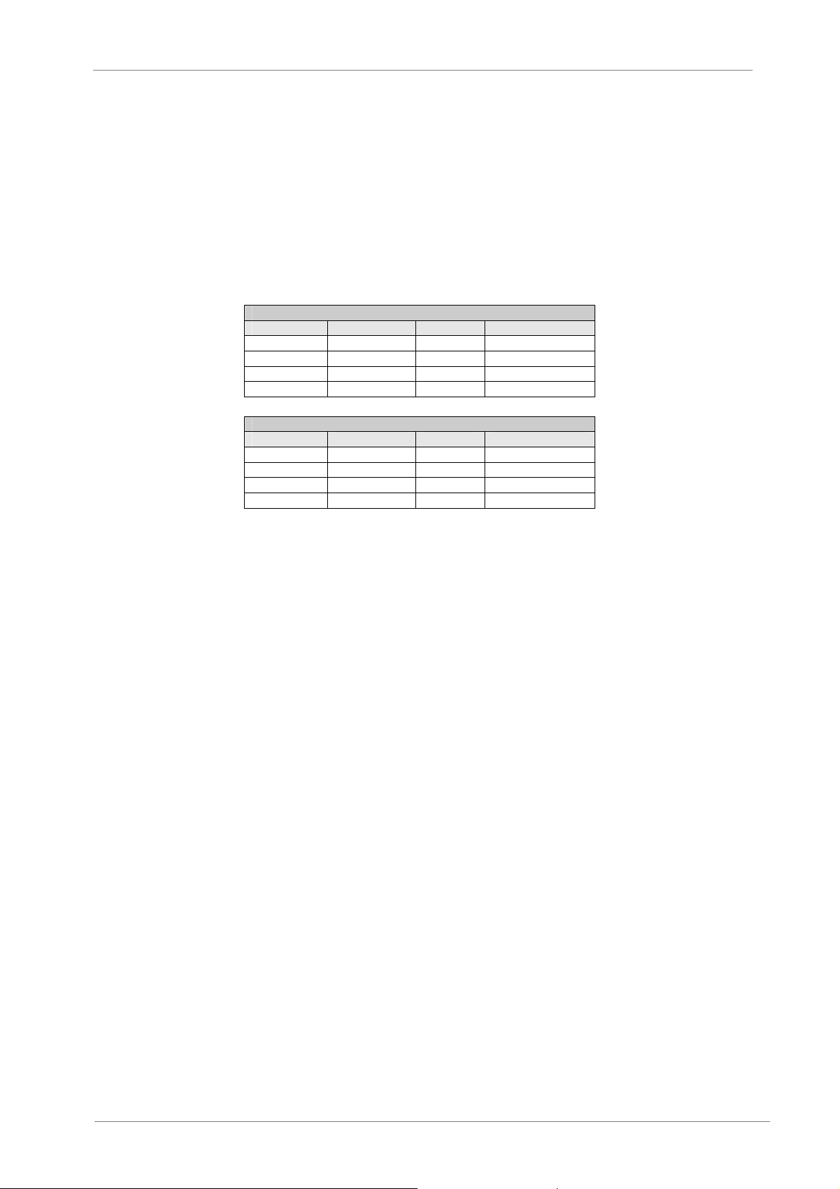
o The controlled silicon high-voltage component are arranged in parallel and in series, the
practical quantity is depending on the motor’s voltage.
VS65
200A and 400A soft starter
Voltage Pairs in Series Total SCR Peak Voltage Ratio
2300V 1 6 6500V
3300 / 4160V 2 12 13000V
6600V 3 18 19500V
10-15kV 5 30 32500V
600A soft starter
Voltage Pairs in Series Total SCR Peak Voltage Ratio
2300V 2 12 7000V
3300 / 4160V 4 24 14000V
6600V 6 36 21000V
10-15kV 6 36 39000V
1.4. Operating Principle
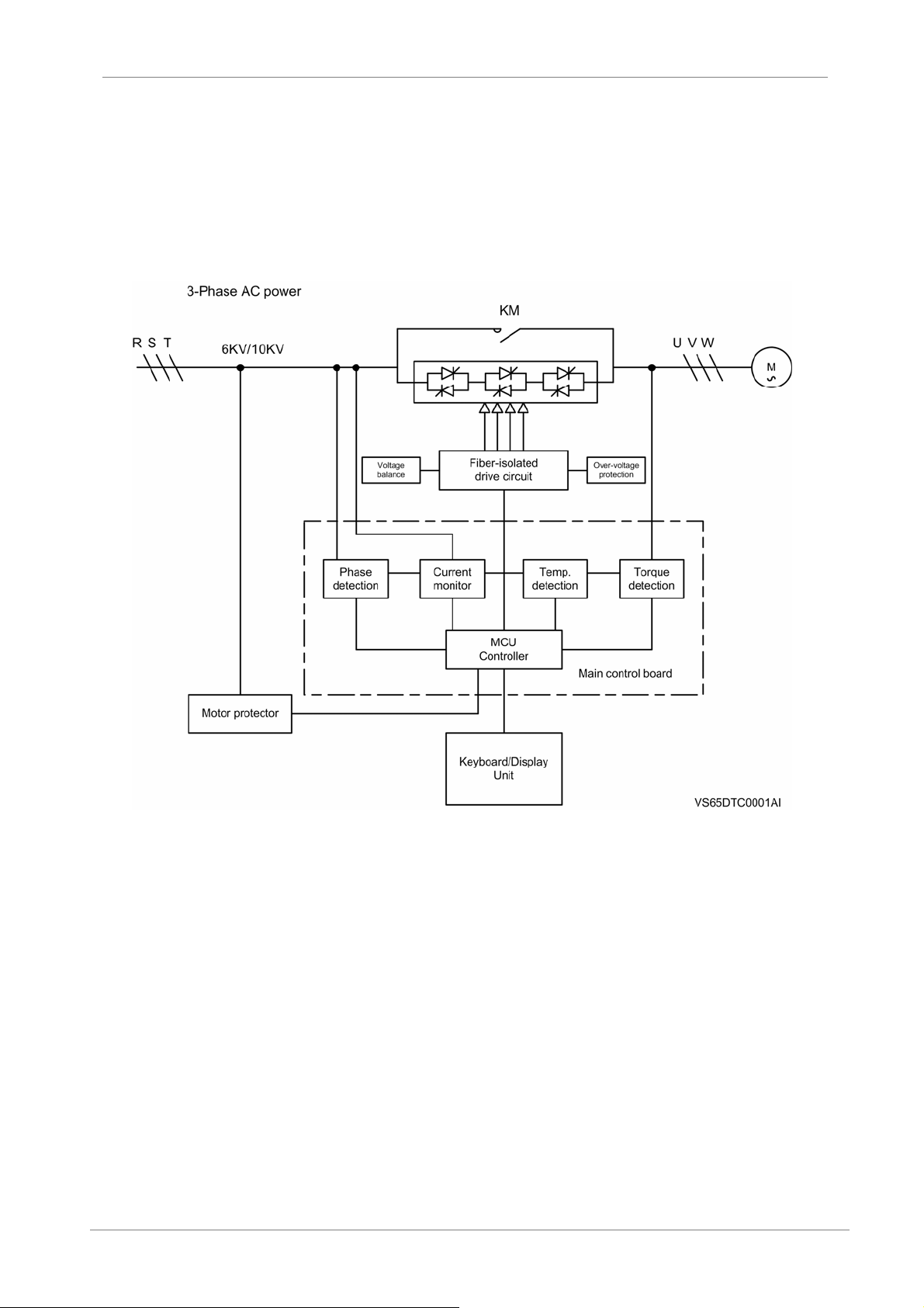
The VS65 has a micro CPU as its control core that can start up and protect the motor. The CPU can
control and trigger the phase angle of SCR in order to reduce voltage applied to motor, and at next
step, by regulating the voltage and current applied on the motor slowly so that the motor torque can
be increased smoothly till the motor runs at full speed after acceleration ramp.
The starting mode can reduce the surge current at motor’s starting stage, decreasing impact on the
electrical grid and the motor itself. Meanwhile, it also can reduce the mechanical impact to the device,
increasing the equipment’s service life and avoid some fault and breakdown.
VS65 series can provide 3 types of starting mode:
Voltage ramp starting mode:
Current-limited starting mode:
The voltage ramp with current-limiting function is the factory configuration and the most
reliable starting mode that meets the most requirements. The initial torque should be set at a
value that just can drive the motor with the load to start. And then the voltage will be rise
smoothly, within a specified ramp time and starting current range till the motor runs at the fullspeed.
During the starting, the current is increased to the specified value rapidly till the motor runs at
the full speed.
INTRODUCTION
13
Page 16
VS65
POWER ELECTRONICS
Heavy load starting mode:
The mode is used mainly in some applications where the motor drives the loads with big
inertia such as the fan, the ball mills, etc. The function can increase 8 seconds to alternative
the bypass circuit in order to avoid excessively impact current due to too earlier switching.
Figure 1.1 Block diagram
1.5. Protection for Motor and System
VS65 soft starter series provides protections for the soft starter and for the motor. These protections
are:
3-phases input loss protection: the motor will only start at 3-phases input supply.
Over temperature protection: this is due to the softstarter startup frequently, that will be resulted in
the controlled silicon working at over temperature (up to 85℃)
Over starting time protection: if the starting time is too long to damage the softstarter and the
motor. The maximum value of starting time is up to 120s.
The softstarter can cut off the output of controlled silicon during the starting or switch off the
bypass vacuum contactor after starting in order to protect the motor. Meanwhile, by the external
detection input (e.g. overload, phase input loss, etc.), these will cut off the power supply.
14
INTRODUCTION
Page 17

POWER ELECTRONICS
Quickly current break (by the main circuit-breaker of MV power supply)
Over current protection, phase imbalance protection, and lock rotor protection
Low voltage & over voltage protection
Over temperature protection of the motor, realized through the motor thermal mode or electrical
measurement.
VS65
INTRODUCTION
15
Page 18

VS65
POWER ELECTRONICS
2. INSTALLATION AND CONNECTION
2.1. Acceptance and Unpacking
VS65 is usually transported upright. For the shipment abroad, the equipment may be placed
horizontally in a container.
Unpack the goods carefully and check for any damage taken placed during the transportation. In
case of damaged, please fill in a damage report within 15 days of reception of delivery order.
Confirm the received shipment accord with the ordered model. The product model is shown on the
label of the low-voltage control board.
2.2. Initial Inspection
Check whether there is damage during transportation and handling.
Check whether there is the loosen parts, broken wires, or loosen connections phenomenon during
the transportation and handling. The loosen connections should increase impedance and affect the
performance.
Before startup, please check and confirm the rated voltage and the rated current.
2.3. Operating Environment
The proper installing location can ensure its normal running and service life. VS65 softstarter must be
installed in an environment meeting these requirements:
Operating temperature: 0~50℃ (32°F-122°F) (running at -20℃ is acceptable if there is the
heating resistance) against rain and moisture.
Humidity: 5~95% non-condensing.
Keep away from the metal scraps, conductive dusts, and corrosive gases.
Oscillation (less than 0.5G).
2.4. Power Connections
Connect the 3-phase medium voltage power lines to the equipment’s input terminals L1, L2, and L3.
Connect the three phases of motor to the output terminals U, V, and W.
The copper bars or the cable must be complied with the standard of the current capacity and the
voltage isolation.
WARNING
Pressing the “Stop” button does not means to cut off the power supply, there is still high voltage
applied to the AC main loop. Prior to maintenance, it is necessary to switch off the main power
supply, i.e. turn off the main vacuum circuit-breaker, and put it at the test position. The WARNING
sign should be adhered on the panel of control cabinet and complied w ith the local electrical
regulations. It is forbidden to connect a capacitance power-factor compensator with the output of
VS65, otherwise will be resulted in the impact current that may damage SCR during startin g. Do
not connect a capacitor to the output of soft starter. If PFC (power-factor compensa tor) is
necessary, please contact with the manufacturer. To avoid the wrong connection of the input and
output terminals; otherwise the logic control circuits will be damaged.
16
INSTALLATION AND CONNECTION
Page 19
POWER ELECTRONICS
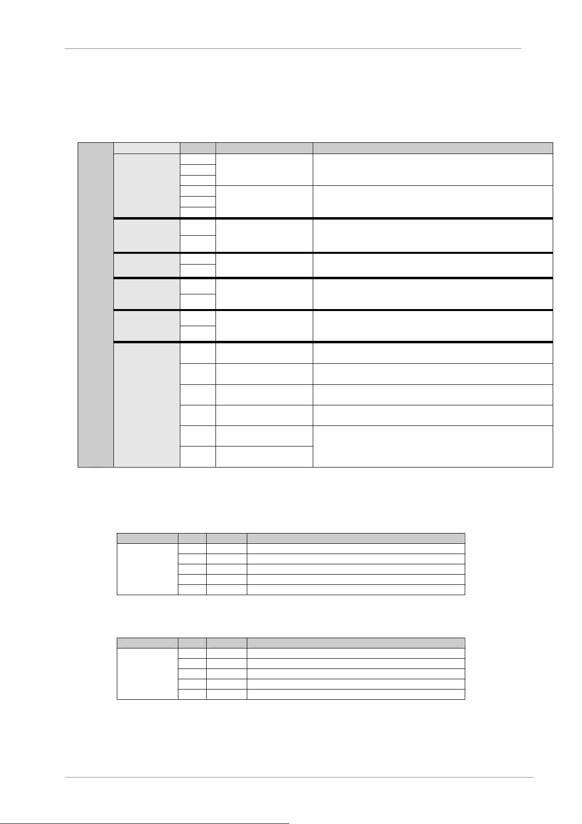
2.5. Control Terminals Description
Descriptions about the terminals on the Control board and the power supply.
PIN SIGNAL DESCRIPTION
L1
AC power input terminal To 3-phase AC power supply via module case circuit-breaker (MCCB).
Soft starter’s output
terminal
AC control power supply’s
input terminal
Fault relay’s output
terminal
Bypass contactor’s control
terminal
MAIN LOOP
CONTROL
POWER
SUPPLY
FAULT
RELAY
BYPASS
CONTACTOR
L2
L3
U
V
W
J10-13
J10-14
J11-1
J11-2
J11-3
J11-4
VS65
To 3-phase asynchronous motor.
To 110VAC 50Hz or 220VAC 50Hz.
Closed in case of fault
Capacity: AC 220V 5A.
Closed as startup is finished
Capacity: AC 220V 5A.
INTERLOCK
RELAY
CONTROL CONNECTORS
INPUT AND
OUTPUTS
J11-5
J11-6
J2-4
J2-3
J2-2
J2-1
J9-1
J9-2
Interlocking relay’s output
terminal
Emergency stop control
terminal
RUN remote control
starting terminal
STOP remote control stop
terminal
COM remote common
terminal
Current signal output
terminal CUT+
Current signal output
terminal CUT
Closed status is controlled by programming
Capacity: AC 220V 5A.
Checking the protector’s fault for Emergency stop
Remote RUN
Remote STOP
Remote common terminal
4-20mA chosen by programming. See 4.3.9
Depending on different field buses chosen by the user, terminal J6 can have different meanings, as
shown in the table below:
Profibus Communication Network:
CONNECTOR PIN SIGNAL DESCRIPTION
J6-1 GND Power ground terminal
J6-2 A Input signal
PROFIBUS
Modbus Communication Network:
CONNECTOR PIN SIGNAL DESCRIPTION
MODBUS
Note: Matched resistance < 200 ohm
J6-3 RST Relay input
J6-4 B Inverse signal input
J6-5 5V Positive power source to be connected with matched resistance
J6-1 GND Power ground terminal
J6-2 A Input signal
J6-3 NC Not Connected
J6-4 B Inverse signal input
J6-5 5V Positive power source
INSTALLATION AND CONNECTION
17
Page 20
VS65
2.6. Connection and Usage of Control Terminals
2.6.1. Preparations for connection
If the user intends to use the external terminals, we suggest using a shielded wire leading out
from the terminal, the shielded should be connected to the ground.
To prevent electro-magnetic interference, the control cable should be kept away from motor’s
cables and other inductive devices.
2.6.2. Connection of relay output terminal
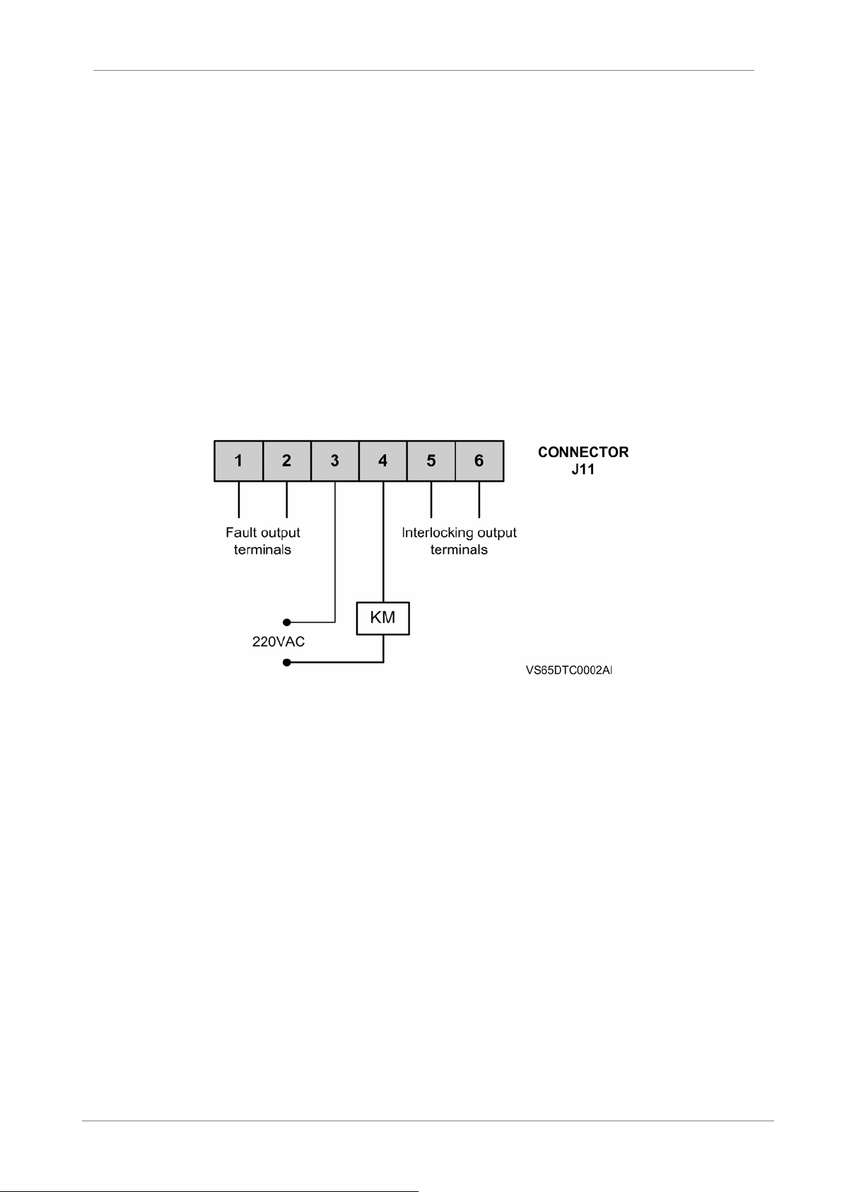
Bypass relay terminals
After the starting process is finished, the inside contact will be closed, the bypass contact KM
will be closed; when the stop instruction is order, the inside contact will be opened (See Fig
2.1).
Figure 2.1 J11 Connector wiring
Fault output terminals
The inside contact can be programmed. It is normally-open at factory setting and can be set
to normally-closed through programming. The contact has capacity of AC 250V 5A.
Interlocking relay output terminals
These contacts are mainly used when the device is interlocked with other equipments. It may
be programmed to select status.
See 4.3.6 contact capacity AC 250V 5A; external control input terminal J2
Emergency stop input terminal
They are used for the external fault signal input. Only be closed, the starter can run. When
they are opened, the starter will stop. The user may program to no use the function.
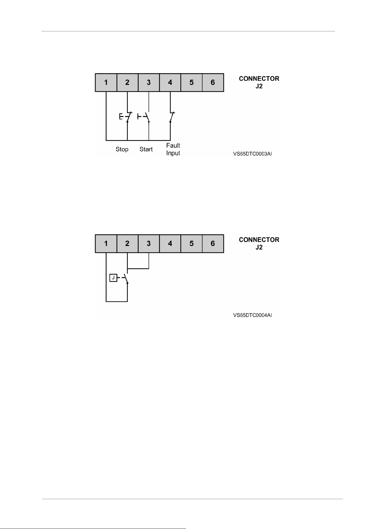
Control terminal (Stop), (Starting), (Common terminal)
The three terminals are to be connected to external startup and stop buttons. They need to
be programmed.
Fig 2.2 shows the three-wire connection method.
POWER ELECTRONICS
18
INSTALLATION AND CONNECTION
Page 21
POWER ELECTRONICS
But the two-wire connection should be practiced for the cases below (See Fig 2.3).
1. When the customer needs only a switching contact to control starting and stop of softstarter,
like the control contact J of PC/PLC.
2. When the delay function of soft starter is used, when J is closed and after a certain delay, the
starter begins starting. The delay value can be set by programming (See 4.3.3 for details).
Analogue current signal output (4~20mA)
This is used to the proportional 4~20mA current signal of main loop, with the proportional
output current can be selected by programming (See 4.3.9).
Operational power supply terminal
Provides power supply 110~220V (AC 50Hz) by a voltage transformer usually.
Field bus terminal
MODBUS RTU and PROFIBUS share the terminal. It is necessary to select the protocol
while ordering the softstarter. See Chapter 7 for the communication protocol.
VS65
Figure 2.2 J2 Connector wiring
Figure 2.3 J2 Connector wiring
INSTALLATION AND CONNECTION
19
Page 22
VS65
3. STANDARD RATINGS
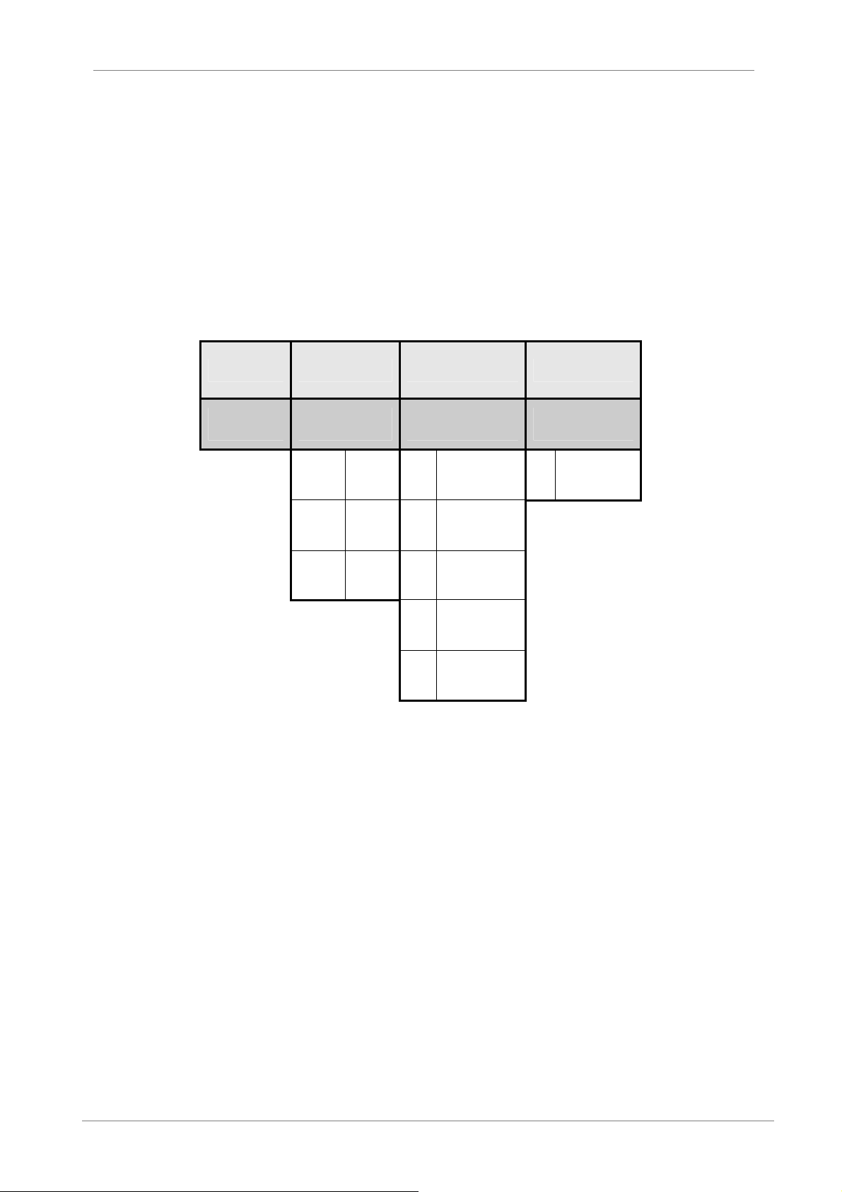
3.1. Designation Code
EXAMPLE
CODE: VS6520064
VS65 200 6 4
POWER ELECTRONICS
VS65
Series
200 200A 2 2300V 4 IP4X
250 250A 3 3300V
... ... 4 4160V
6 6600V
10
Output
Current
Input
Voltage
10000V –
15000V
Protection
Degree
20
STANDARD RATINGS
Page 23
POWER ELECTRONICS
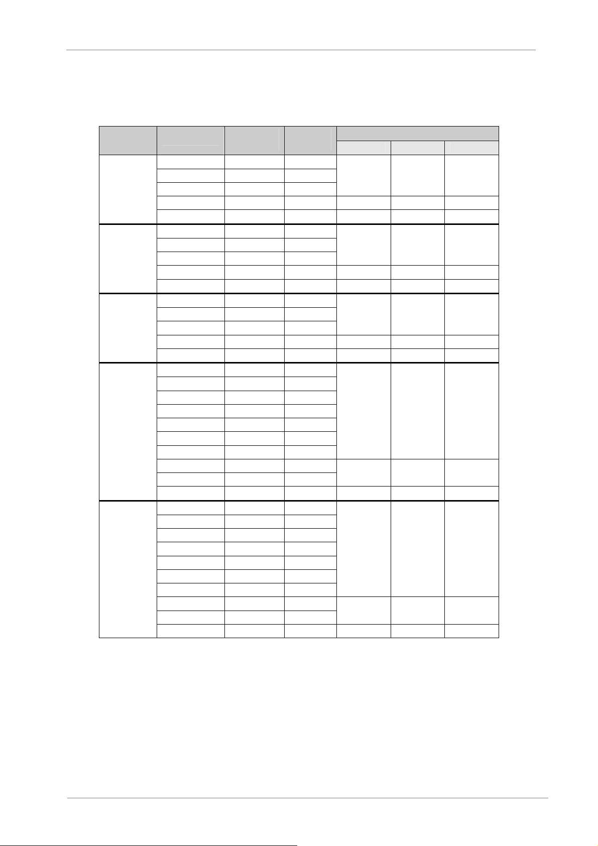
3.2. Table of Standard Ratings
VOLTAGE
(V)
2300
3300
4160
6600
10000 –
15000
Notes:
1. To indicate the Protection Degree, replace X by the first number of it (for example: Replace X by 4 for
IP40).
2. For different voltages and currents, contact with Power Electronics.
CODE
VS651002X 100 340
VS652002X 200 680
VS654002X 400 1360
VS656002X 600 2040 2300 2600 1510
VS658002X 800 2720 Customized Customized Customized
VS651003X 100 490
VS652003X 200 980
VS654003X 400 1960
VS656003X 600 3660 2300 2600 1510
VS658003X 800 3920 Customized Customized Customized
VS651004X 100 610
VS652004X 200 1220
VS654004X 400 2440
VS656004X 600 3660 2300 2600 1510
VS658004X 800 4880 Customized Customized Customized
VS651006X 100 880
VS651506X 150 1320
VS652006X 200 1760
VS652506X 250 2200
VS653006X 300 2640
VS653506X 350 3080
VS654006X 400 3520
VS654506X 450 3960
VS656006X 600 5280
VS658006X 800 7040 Customized Customized Customized
VS6510010X 100 1470
VS6515010X 150 2210
VS6520010X 200 2940
VS6525010X 250 3680
VS6530010X 300 4420
VS6535010X 350 5150
VS6540010X 400 5880
VS6545010X 450 6620
VS6560010X 600 8840
VS6580010X 800 11760 Customized Customized Customized
CURRENT
(A)
POWER
(kW)
VS65
DIMENSIONS (mm)
H W D
2300 1800 1510
2300 1800 1510
2300 1800 1510
2300 1800 1510
2300 2600 1510
2300 1800 1510
2300 2600 1510
STANDARD RATINGS
21
Page 24
VS65
4. PROGRAMMING KEYBOARD
4.1. Display and Keyboard
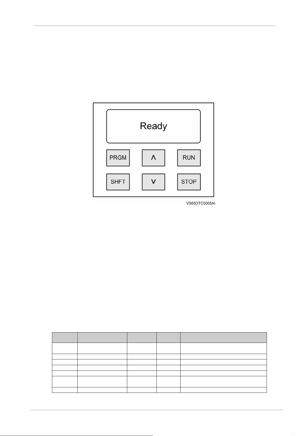
LCD is the display device, which is divided into text and character display zones. The text zone
shows various parameters value and the character area indicates status of the softstarter.
Figure 4.1 Keypad and Display unit
Keys function is:
RUN: Press the key in the ready status to start up the motor
STOP: Press the key to stop when the motor is running; press it to be reset from the program
status or fault status to the ready status.
SHFT: Used together with the PRGM key in parameter setting
PRGM: Set the parameters and enter the fault history
Λ: Increase the value or in the running status to display the max. starting current and max.
running current.
V: Decrease the value
POWER ELECTRONICS
4.2. Function Code Table and Description
Code
Function
00
01 Rise time 0-100s 10s Effective in all modes
02 Stop time 0-60s 2s 0: free stop
03 Starting delay 0-240s 0s Effective in two-wire control
04 Current limited 150%- 500% 250% Effective in heavy load& current limiting modes
05 Emergency stop 0-1 0
06 Interlock delay 0-240s 0s See interlocking of code 7
22
PROGRAMMING KEYBOARD
Name Range Default Description
Starting voltage
30-80%
30% Effective in voltage mode
0: without emergency stop
1: with emergency stop
Page 25
POWER ELECTRONICS
Code
Function
07 Interlock control 0-6 0 0: delay See 4.3.6
08 Starting mode 0-6 0
09 Control mode 0-5 1
10
11 Current display 0-1000 0
12 Fault relay 0-1 0
13 Slave address 0-125 0 Slave address setting
14
15 Communication 0-1 0 0: Modbus 1: Profibus
16 Communication speed 300-19200 0 96 means 9600
17 Parity check 0-2 0 0: Non parity 1: Odd 2:Even
18 Communication bus 0-1 0 0: PPO1 1: PPO 3
19 Communication bus fault 0-1 0 0: Only alarm 1: alarm and stop
20 RET program 0-2 0
21 Language 0-1 0
22 Invary void 25% - 80% 35% It is valid under the voltage or heavy load mode
23 Invary time 5-60s 20s It is valid under the voltage or heavy load mode
24 Write protection 0-1 0
Note: 1. Function codes will not lose after power loss till they are modified.
2. Function codes can be changed to default values see in 4.4.3.
3. Function codes maybe different as updated version. Please refer to the latest version.
4. In case of using communication function, the device needs to be repowered after the slave address is set.
Name Range Default Description
0: Current limiting 1:Voltage
2: Heavy load
0:Keypad 1: Remote
2:Keypad + remote 3:PC 4:Keypad + PC
5:Remote +PC
Analogue current
selection
Restart 0-1 0
0-5 0 0-20mA current
0: percentage of SS rating
1-1000: actual motor current
0: Normal-open
1: Normal-closed
0:Not allowed
1:Allowed,only two-wire control
0: reset is disable
1: reset is enable
It allows selection of the user language.
0: English
0: Without protection
1: With protection
VS65
4.3. Function Code Explanations
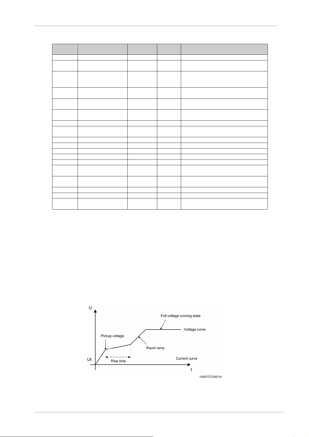
4.3.1. Code 00 – Pickup voltage. Code 01 – Rise time
They are starting control parameters under the voltage mode. Increasing the pickup voltage can
help to overcome the static-friction force during the starting; if bigger load inertia, you have to set
a longer rise time (as shown in Figure 4.2).
Figure 4.2 Starting ramp
PROGRAMMING KEYBOARD
23
Page 26
VS65
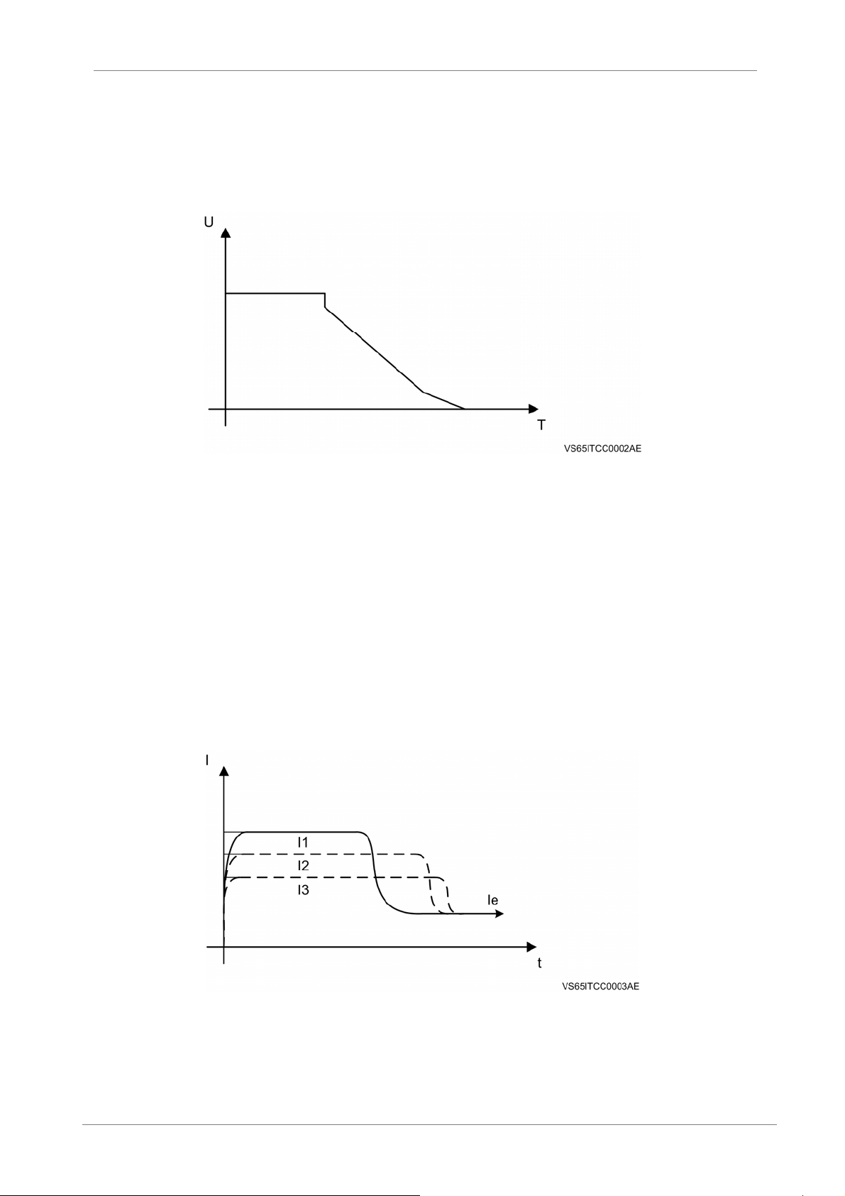
4.3.2. Code 02 – Shutdown time
The shutdown time of 0 second means the free stopping. Excessive shutdown time maybe cause
the system is instable. (See Figure 4.3).
POWER ELECTRONICS
Figure 4.3 Stop mode
4.3.3. Code 03 – Starting delay
This is the duration from the moment while the remote startup is closed (two-wire type) until the
softstarter begins running. To use this function, the Code 09 must be set to 1. While the remote
control terminals RUN, STOP, and COM are connected and the countdown value is 0, the
softstarter will startup.
4.3.4. Code 04 – Limiting current
To use the function, Code 08 must be set to 0. The starter will begin starting with starting current
below the set value (150%~500%). When the starting is finished, the current will drop below the
rated value. If the value is larger, the allowed starting time is shorter.
Figure 4.4 Limiting current
24
PROGRAMMING KEYBOARD
Page 27
POWER ELECTRONICS
4.3.5. Code 05 – Emergency stop setup
By setting the code 0 or 1, the user can turn on or turn off the remote emergency input. Setting 0
is disabled, setting 1 is enabled.
4.3.6. Code 06 – Interlocking delay. Code 07 – Interlocking control
The starter’s interlocking output is controlled by programming these two values. The set value of
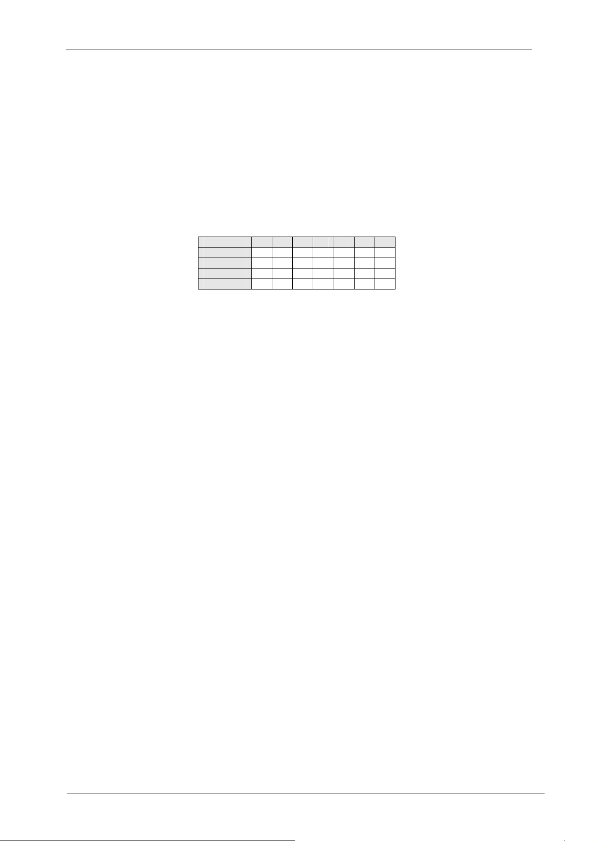
Code 06 represents the delay time from the moment when the starter startup until the terminals is
closed. The code 07 can be assigned a control method of interlocking relay. See table on section
4.2. Code 07 must be 0 if delay.
0 1 2 3 4 5 6
START ● ● ●
RUN ● ● ● ●
STOP ● ● ●
DELAY ●
Note: Marked as “●” means “Interlock” relay is closed
VS65
4.3.7. Code 08 – Starting mode
If set to 0, it means the current mode. See 4.3.4 for starting limiting current.
If set to 1, it means the voltage mode. See 4.3.1
If set to 2, it means the heavy load mode.
4.3.8. Code 09 – Control mode
0: Only the keys RUN and STOP can be used to control startup and shutdown.
1: Remote control. Only RUN/STOP by two-wire or three-wire.
2: Keyboard + Remote control (applicable for the three-wire control method)
Both keyboard and remote control can be operated, but only the STOP-COM is closed, the “RUN”
key of keypad can be valid,
3: PC is operated by communication bus to control and monitor.
4: Keyboard + PC: Both keyboard and communication bus is valid.
5: Remote control + PC: remote RUN, STOP and communication bus is valid.
PROGRAMMING KEYBOARD
25
Page 28
VS65
POWER ELECTRONICS
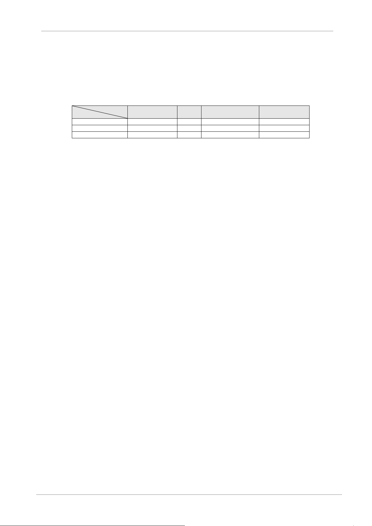
4.3.9. Code 10 – Current signal selection
Measure the proportional current signal according to the load. Four options are available, as
shown in following table.
Set Value
Output current mA 0 – 10 0 – 10 4 – 10 4 – 20
Rated Value 500% 150% 500% 150%
Formula % (2) D=50Ix D=15Ix D=(500 / 16) • (Ix-4) D=(500 / 16) • (Ix-4)
Note: The analogue current is proportional to the actual load and the maximum value is 20 mA (or 10 mA) of output
current.
Ix: the measured current value (mA), D: the motor load current (%)
0 1 2 3
4.3.10. Code 11 – Display mode
0: the Current displayed is shown as the percentage of the rated current value of softstarter, i.e.
100% represents the rated current of softstarter.
XXX: the rated current of motor is setting between 1 and 1000, meanwhile the actual output
current value is displayed on the LCD.
4.3.11. Code 12 – Fault relay setting
The user may set the fault relay’s status to normal-open (0) or normal-closed (1).
4.3.12. Code 13 – Tributary address
This is used to set the slave address of field bus. For the same master, the slave address will be
unique. Refer to Field Bus Communication in Chapter 7.
4.3.13. Code 14 – Restart
When the starter is stopped due to the fault, setting Code 14 to 1 can cause the starter
automatically running after 6s delay. If it is set to 0, the starter can only be restarting after reset.
The function is only valid in the two-wire method.
4.3.14. Code 15 – Communication bus
It allows selection of communication bus between 0: MODBUS and 1: PROFIBUS.
4.3.15. Code 16 – Communication speed
This is used for selection of communication speed by MODBUS communication, the possible rang
is from 300 to 19.2k bps.
See 7.2 for information on usage.
26
PROGRAMMING KEYBOARD
Page 29

POWER ELECTRONICS
4.3.16. Code 17 – Even-odd check
This is used for selection of check method by MODBUS communication. It should be in
accordance with the master device.
4.3.17. Code 18 – Bbus mode
This is used in PROFIBUS, with 0 for Method 1 where parameters modification is allowed and 1
for Method 2, where only starter monitoring is performed. Refer to 7.1.
4.3.18. Code 19 – Bus fault
In case the communication control is selected, when the communication bus connection is faulted
(connection failure), the starter may choose a status between: 0: only alarm without stop; and 1:
stop with alarm.
4.3.19. Code 20 – RET terminal control (not be used)
VS65
RET: This terminal is multifunctional. When set to different values, the code has different
functions as described below:
0: Used as a remote reset terminal, the same RST function as the STOP key on keyboard;
1: Locks remote control terminals RUN and STOP, which means when RET terminal is connected
to the COM terminal, RUN and STOP will be disabled from controlling starter.
2: Locks communication bus control, which means when RET terminal is connected to the COM
terminal, using bus to control startup and stop of the starter is forbidden.
4.3.20. Code 21 – Language
It allows selection of the user language. User can select English.
4.3.21. Code 22 – Invary void
According to the load type, the user can set a fixed voltage value during the starting period of
motor. Once elapsed the time set in code 23, the voltage will be increased at certain ramp.
4.3.22. Code 23 – Invary time
According to the load type, the user can set the time value for keeping a fixed voltage during the
starting period.
4.3.23. Code 24 – Write protection
When Code 24 is set to 1, parameter modification is not allowed. If want to modify the
parameters, you have to set this value to 0 to modify them.
PROGRAMMING KEYBOARD
27
Page 30
VS65
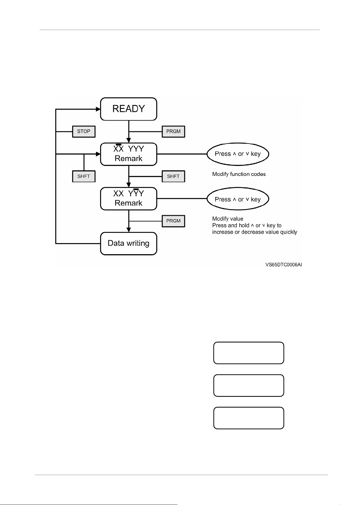
4.4. How to program
4.4.1. Programming flow chart
Note: Once data is written, it will be kept till it is modified at next time. Power loss will not
erase the written data.
POWER ELECTRONICS
Figure 4.5 Block diagram for programming
4.4.2. Programming example (modify current limiting value)
28
A. Press ”PRGM” key
B. Press “Λ“ key four times
C. Press “SHFT” key
PROGRAMMING KEYBOARD
00 30%
Starting Voltage
00 150%
Current limiting multiple
04 150%
Current limiting multiple
Page 31
POWER ELECTRONICS
VS65
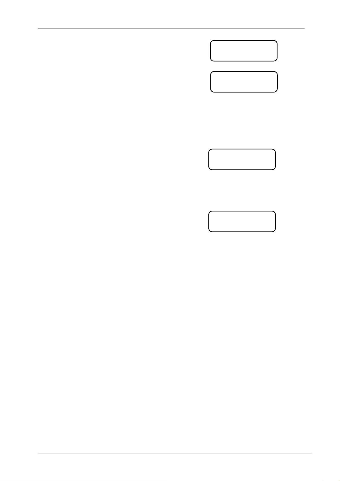
D. Press and hold “Λ“ key till the
indicated value reaches 300%
E. Press ”PRGM” key
4.4.3. How to input default values
If a fault of parameter occurs, it is necessary to input factory (default) value.
Please follow the steps below.
A. Return to the ready status
B. Press ”STOP” key for more than 4s
C. When the screen shows “Data Write-in” input
the default value
04 300%
Current limiting multiple
04 300%
Data writing
Ready
Data Write-in
PROGRAMMING KEYBOARD
29
Page 32
VS65
5. POWERING ON AND RUNNING
5.1. Low-Voltage Trial Run
It is necessary that the starter have to be running at a low-voltage test firstly, in order to ensure it can
be running normally while the medium voltage input. This test is done at manufacturer installations
where corresponding test conditions can be considered. A short description is here included.
Preparations include:
Incoming lines L1, L2, and L3 are connected to the 380V 3-phase power supply.
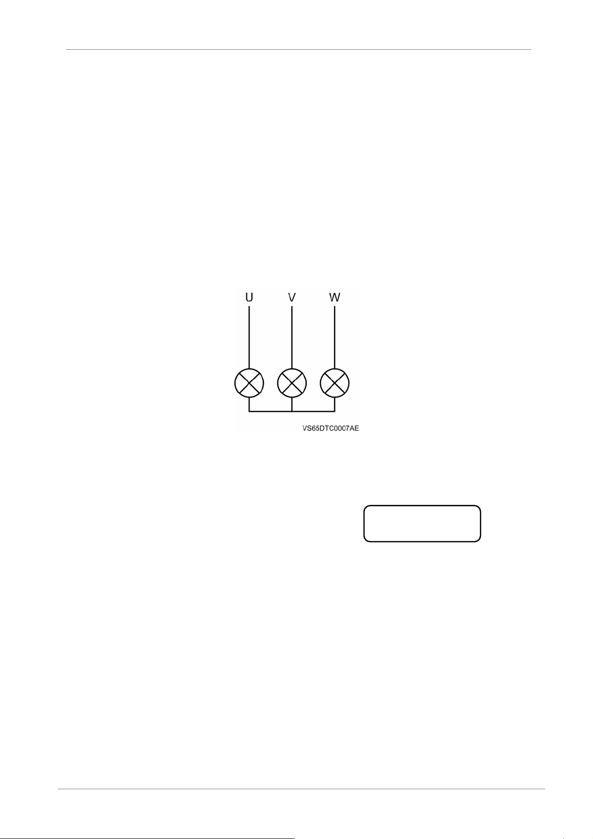
Output terminals U, V, and W are connected to 100W lamp as the load to indicate.
Control power supply input : 220V AC
Figure 5.1 Incandescent lamp with power over 100W
A. When the control power is on and the
LCD should show the following screen for 2s
B. The text zone shows:
READY: this is the status after reset.
C. Press the RUN key on the control panel to begin starting. Please monitor the all lamps,
which should be brighter gradually, if three phases are balance.
POWER ELECTRONICS
Ready
30
POWERING ON AND RUNNING
Page 33

POWER ELECTRONICS
5.2. High-Voltage Trial Run
Set up connections for the main loop according to 2.4. Since the soft starter’s incoming lines do not
have section breakers, it is necessary to power on the cabinet by using the main circuit-breaker on
the incoming cabinet. Prior to providing medium-voltage current, the user must check and confirm all
connections are correct and the cabinet door is closed.
Based on the motor load at the field, the user should adjust various parameters of the soft starter,
allowing the motor to obtain the optimum starting torque.
When pressing Key RUN, check and find whether the motor is revolving according to requirement.
For any abnormal conditions, press Key STOP to shut down. If the motor does not revolve, raise the
pickup voltage to increase the starting torque.
In case of faults during running, identify the reason by referring to 6.2. Pressing Key STP or closing
the external control terminal RET can perform a reset.
5.3. Data Display in Running
VS65
Phase B current is displayed after running.
During running, use Key ∧ to have the maximum starting current displayed instead.
Then press Key ∨ to display the maximum running current.
If the function code 11 is set to 0, the Phase B current is displayed in percentage; when the code is
set to motor’s rated current, the current is displayed in its actual value.
For a starting time longer than 30s (e.g. for blower fan), please use the heavy load starting mode.
POWERING ON AND RUNNING
31
Page 34
VS65
POWER ELECTRONICS
6. FAULT MESSAGES. DESCRIPTIONS AND
ACTIONS
The VS65 soft starter have the comprehensive protection function, it can stop in case of any fault, display
and save the fault codes. The fault status only can be reset by using the STOP (RST) key (* if using the
fault reset automatically, it will be starting automatically, please be carefully to ensure the safety)
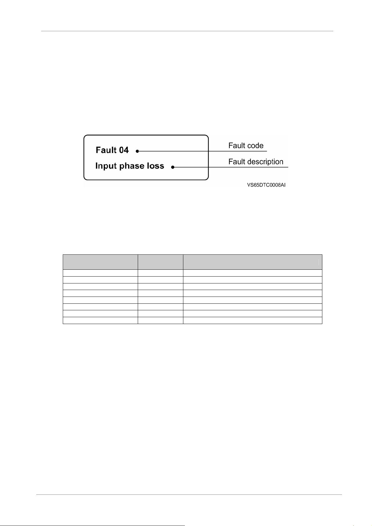
Figure 6.1 Fault display
6.1. Fault Code Table
Fault Description Fault Code Cause and Troubleshooting
Emergency stop 1 Fault from motor protection; check the general protector
Too long starting time 2 Limited current is too low or over heavy load
Over heated 3 Too frequently starting or too long starting times
Input phase loss 4 Check power supply and controlled silicon
Error parameter 5 Restart or input default value
Error frequency 6 Check frequency of 3- phase AC power supply
Communication fault 7 Fault in communication interface
Connection failure 8 Check external connection of J6
Note:
1. Motor is only protected against overload and overcurrent, phase imbalance, etc.
2. Please refer to the motor general protection manual (SNP-2371) for the detailed information of the motor
protection.
32
FAULT MESSAGES. DESCRIPTIONS AND ACTIONS
Page 35
POWER ELECTRONICS
6.2. Fault History
The soft starter can save up to 5 faults history for analysis in future.
6.2.1. Display the saved fault
When the starter is in the ready status (or fault status), press “PRGM” for more than 4 seconds.
The No.1 fault is the latest fault and the new faults will overwrite the previous ones.
Press the ”∧” key to view the previous fault.
VS65
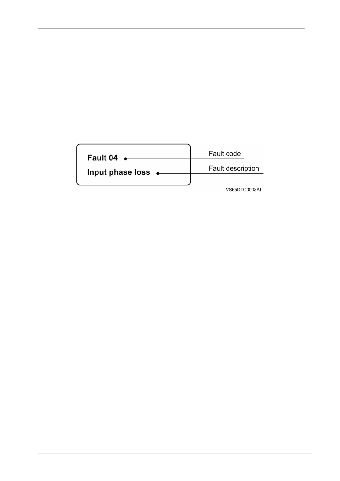
Figure 6.2 Saved Fault
6.2.2. Fault clearance
After all faults are reviewed, it is recommended to erase all fault history. To do this, press “PRGM”
for more than 4 seconds when viewing the saved faults.
FAULT MESSAGES. DESCRIPTIONS AND ACTIONS
33
Page 36

VS65
POWER ELECTRONICS
7. COMMUNICATION PROTOCOL
The customer can select the protocol between Modbus and Profibus when placing orders. In case of
choosing communication bus controlling, the function code 09 must be set to 04, 05, or 06 to activate the
communication function.
7.1. Profibus Protocol
The device uses Profibus-DP to implement the communication function. The protocol standard is
specified by EN50170. The Profibus communication interface has the following features:
The Profibus performs cyclic communication rapidly;
The Profibus supports baud rate up to 12MHz;
Up to 125 soft starters can be controlled;
With a Profibus debugging tool, configuring is very easy;
The built-in Profibus communication module is very convenient in connection setup;
All control parameters of soft starter can be set, modified by serial bus;
The response time of data is 5ms.
Principles for quickly setup
It is necessary to connect with the cable between the master and softstarter correctly, including
terminal resistance (for communication rate of 12M).
The bus cable should be a shielded cable, the shielding should be connected to ground.
The bus must be in running status;
The softstarter must be power-on.
The slave address (function code) of soft starter must be set correctly and consistent with that on
the master. The soft starting address must be unique.
When the soft starter shows a fault of connection, please check the connection cable between the
master station and the softstarter, the slave address, and other parameters.
The terminal A and B should be connected to 220ohm resistance in parallel. When multiple
devices are connected in parallel, only one of them needs to be connected with a resistance.
7.1.1. Application protocol
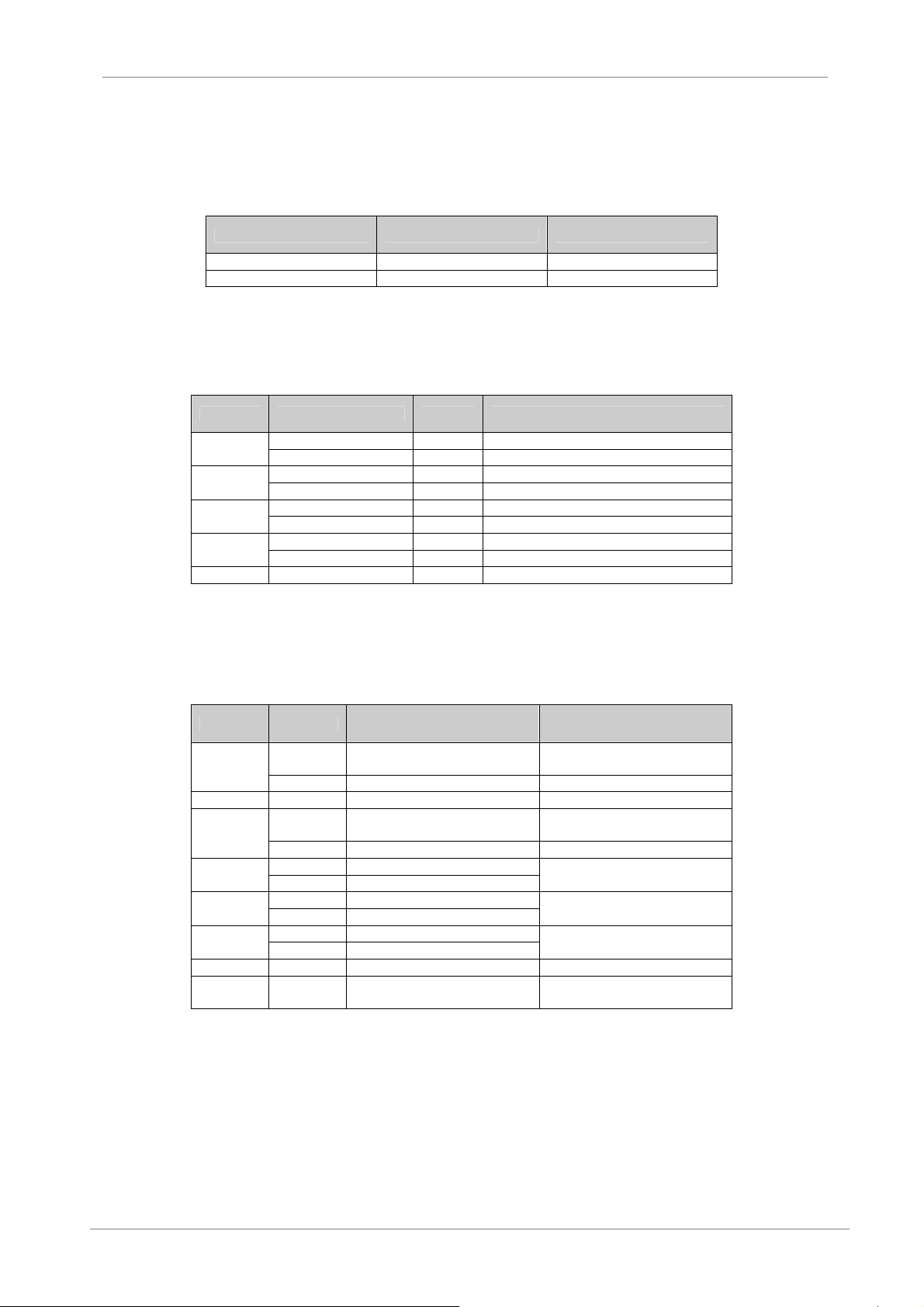
The Profibus controls VS65 by data blocks. There are two data areas, the Parameter
Identification Area PKW and the Process Control Area PZD, occupying 2 words in input/output
respectively. The former is used to read and modify starter’s function parameters and the latter is
used to control and monitor status and current. The master station’s configuration is given by
GSD file (See the table below).
Parameter Identification PKE Process Control PZD
IND PWE STW --
INDH INDL ZSW ACT
1 2 3 4
IND: Parameter index; PWE: parameter value; STW: Control word; ZSW: Status word; ACT:
Actual current value
The user may choose Type I (PPO1), which allows full operations on softstarter’s parameters
and control & monitoring; when parameter modification is not necessary, Type III (PPO3) may be
used.
34
COMMUNICATION PROTOCOL
Page 37
POWER ELECTRONICS
7.1.2. Parameter explanation
When PPO1 is chosen, function parameters of VS65 can be read and modified. The high byte
(INDH) of parameter index (word) IND is task request, the low byte (INDL) is parameter address,
which corresponds to the address of function code. PWE is the value of visited parameter. All
values are the hexadecimal.
INDH Meaning
0 No task
1 Read a parameter at address INDL
2 Modify a parameter at address INDL; value written in PWE
INDH Meaning
0 No response
1 Pass a parameter, value in PWE
2 No right to modify
3 Task cannot be executed.
With the response of 3, the task can not be executed, the operated parameter cannot be read or
written. The table below is the error types. Codes of error types are read from PWE.
VS65
Task Request
Task Response
PWE Meaning
0 Parameter unavailable
1 Parameter cannot be modified
2 Value beyond upper/lower limit
3 Cannot be modified because it is running
4 Service not supported
Codes for task response of 3
7.1.3. Parameter operation examples
1. Operation on VS65 done by master station
Read value of the function Code 01 (rise time)
MASTER Î VS65 01 01 00 00
VS65 Î MASTER 01 01 00 0C
This means the read rise time is 12s.
2. Modify the function code 04 (current limiting) to 350%, i.e. 15E is hexadecimal.
MASTER Î VS65 02 04 01 5E
VS65 Î MASTER 01 04 01 5E
If the response code is 03 04 00 03, this means modification is denied because the starter
is running.
COMMUNICATION PROTOCOL
35
Page 38
VS65
7.1.4. PZD (process control) explanation
The PZD area is to control and test the soft starter.
PZD1 PZD2
MASTER – VS65 STW ----
ZSW ACT
STW control word is used to start, stop and fault reset of soft starter.
Bit Name Value Remark
POWER ELECTRONICS
0
1
2
3
4-15 No used 0
Status word ZSW is used to check starter’s status
Bit Value Meaning Note
15
14-12 Unused
11
10
9
8
7-6 Unused
5-0 0
ACT is current value, which, depending on the function code 0B (11), is shown as the percentage
of motor’s actual current value. The value is the hexadecimal.
Startup 1 Use the starter to perform starting
Soft stop 0 Use the starter to perform soft t stop
Working 1 Continuous work
Free stop 0 Free stop
Reset 0-1 Use the starter to perform a reset
Normal running 0
PLC control 1 Bus control
Not operated 0
VS65 control word STW
1 Starter faulted
0 Starter normal
1
0 Shown in actual current value
1 Soft stop state
0 Stop status
1 Running state
0 Shutdown state
1 Starting state
0 Shutdown state
Current value shown in
percentage
th
bit being 1 indicates a
The 15
fault code
VS65 status word ZSW
Clear fault according to 0-5 fault
codes
Phase A displayed for ACT
Phase A displayed for ACT
Phase A displayed for ACT
Consistent with fault code in the
manual
36
COMMUNICATION PROTOCOL
Page 39
POWER ELECTRONICS
PZD examples
Example 1: Start the starter
MASTER Î VS65 00 0B 00 00
VS65 Î MASTER 09 00 00 F0
This means the starting status, with current value of 240%.
Example 2: Stop the starter
MASTER Î VS65 00 0A 00 00
VS65 Î MASTER 0C 00 00 F0
This means the stopping status, with current value of 240%.
Example 3: Fault occurs in the softstarter
The status word 8A 06 00 50 is received by VS65, this means a fault during running. The
fault code 06 means overcurrent in Phase A.
PZD data is refreshed constantly during running. Before other operations, the current
command must be stopped. The status word always indicates the running condition of
VS65. Current value is also refreshed constantly.
VS65
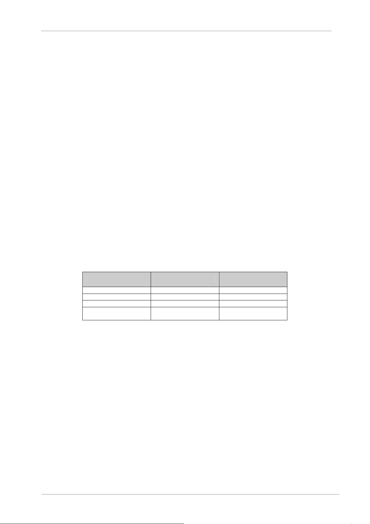
7.1.5. Communication setup
The setup of the function codes below is associated with communication and needs to be done on
the keypad.
VS65 Function Code Content Set value
09 Control mode 3&4&5
13 Slave address 0 – 126
15 Communication method 1: PF mode
18 Communication mode
Note: To take the parameters into effective, re-power is required.
0: PPO1
1:PPO3
COMMUNICATION PROTOCOL
37
Page 40
VS65
7.2. Modbus Protocol
This section will explain how to control various operations of VS65 through Modbus communication.
7.2.1. Overview about Modbus
Modbus is a serial asynchronous communication protocol, with physical interface of RS485.
Modbus protocol is designed for modicon PLC, has structural features of PLC. The VS65 soft
starter can be read and write in the Modbus network. VS65 put the startup & stop, the status of
the information (current, fault, etc.) and function parameters into the holding register (4xxxx).
When using, read and writing is controlled by using the PL master station.
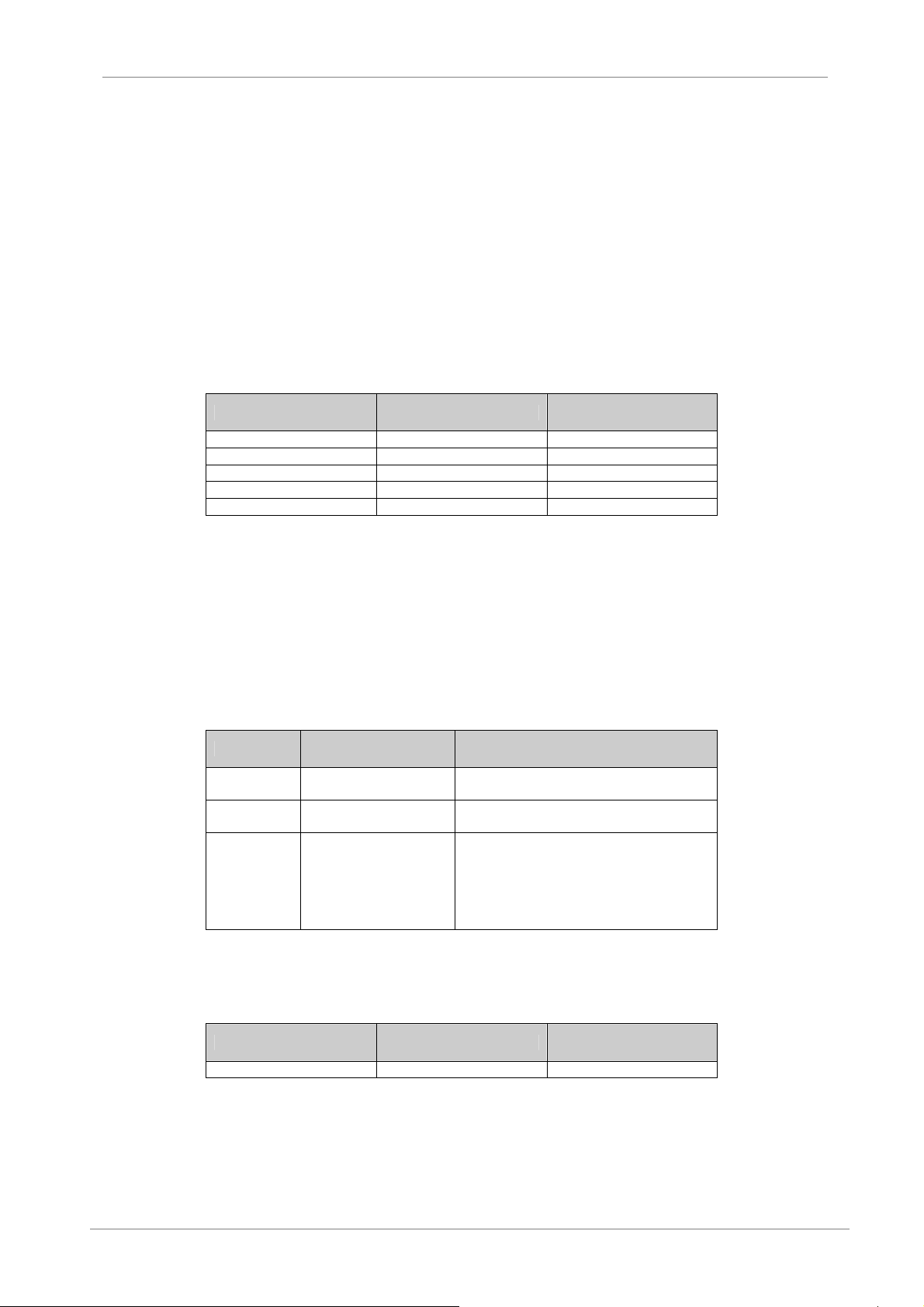
Register address Operation code
40001 06 Control word
40002 03 Status word
40003 03 Current average value (%)
40004 03 Fault code
40257 – 40281 03&06 Soft starter function code
(1) Registers not listed above are illegal and cannot be read; otherwise, VS65 will report an
exceptional code to the controller.
(2) All data addresses are based on the reference of 0. For example, the relay coil 40001
has the address of 0000, 40257 has the address of 0100 (hexadecimal).
POWER ELECTRONICS
Register functions
explanation
7.2.2. Exceptional codes
VS65 supports standard Modbus exceptional codes (See the table below):
Code Name Remark
01 Illegal function
02 Illegal data address
03 Illegal data value
VS65 only supports Modbus functions codes listed in the below Table. If other codes are used,
exceptional code 01 will be given.
Code 03 06
Function description Read the memory register Preset individual registers
Code 03 is only used for single word (WORD) reading.
(1) Registers not listed above are illegal and cannot be read; otherwise, VS65 will report an
exception code to the controller.
(2) All data addresses are based on the reference of 0. For example, the coil relay 40001
is the address of 0000 and 40257 is the address of 0100 (hexadecimal).
Function code cannot be executed, because
VS65 does not support it.
Data address received cannot be executed.
Address out of range.
Data received cannot be executed.
1. Parameter beyond limiting
2. Parameter cannot be modified
3. Parameters cannot be modified during
running
38
COMMUNICATION PROTOCOL
Page 41
POWER ELECTRONICS
7.2.3. Register Information
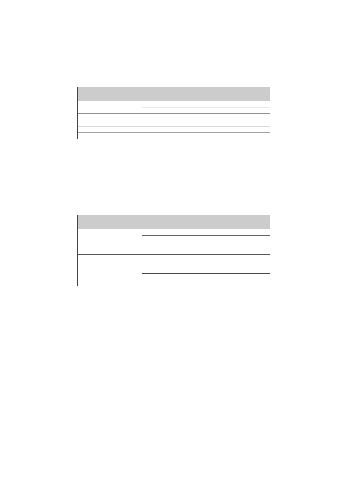
40001 command register
Bit Value Description
VS65
0
1
2 0 – 1 Reset starter
3 – 15 0 Unused
Example: To start the softstarter with the slave address 02. The controller sends 02 06 00
00 00 01. If the command is executed normally, the code 02 06 00 00 00 01 will be
returned. Checking the status register whether the starter started normally. If there is the
fault, the code 02 06 00 00 00 04 should be sent to reset.
Register address 40002 state register
The state register reflects the state of soft starter, which is expressed with a word.
Bit Value Description
0
1
2
3
4 – 15 Unused
Example: Reading the code of status 02 03 00 01 00 01
If the starter is in the starting process, the code 02 03 02 00 01 will be returned.
If a fault occurs to the starter, the code 02 03 02 00 08 will be returned.
40003 current average value (hexadecimal system)
The value is VS65 average value of 3-phase actual current, which is shown in percentage
or actual value depending upon setting of the function code 0B.
Example: Read current value
Send the code 02 03 00 02 00 01.
If the current is 235A, the code 02 03 02 00 EB will be returned.
40004 fault code (hexadecimal)
When the 3rd bit of status register 40002 is 1, VS65 is in fault status, with the fault code
being consistent with 6.1.
Example: Send 02 03 00 03 00 01
If the code 02 03 02 00 04 is returned, it means there is the input phase loss (fault code 04).
1 Starter starting
0 Hold mode
1 Starter shutdown
0 Hold mode
1 Starting state
0 Shutdown state
1 Running state
0 Shutdown state
1 Soft stop state
0 Shutdown state
1 Fault state
0 Normal state
COMMUNICATION PROTOCOL
39
Page 42
VS65
Function parameter register 40XXX of soft starter
XXX-1 is as 1YY in hexadecimal and YY corresponds to code value in table on section 4.2.
For example, 108 corresponds with 08 (starting mode). Reading or writing these function
codes is possible. Examples are below.
Example 1: Read the function code 04 (current-limiting value)
The controller sends 02 03 01 04 00 01.
The read value of function code 04 is returned. For example, 02 03 02 01 5E means the
current limiting value is 350%.
Example 2: Read the function code 0C (protection level)
The sent code is 02 03 01 0C 00 01. A returned code 02 03 02 00 03 is the protection level
3.
Example 3: Modify the function code 04 (starting current) of soft starter to 250%.
The master sends 02 06 01 04 00 FA and VS65 returns the code 02 06 01 04 00 FA. If the
code 02 86 03 is returned, it means writing is disable, possibly because the starter is
running.
7.2.4. Connection and setup
POWER ELECTRONICS
The setup of the function codes below is associated with communication and setting on the
keypad.
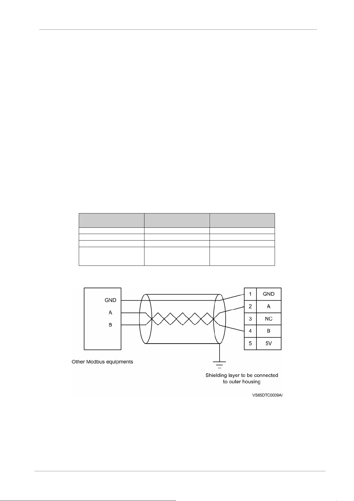
VS65 Function Code Content Set value
13 Slave address 0 – 245
15 Communication method 0: Modbus mode
16 Communication rate 300 – 19200bps
0: none
17 Check mode
Figure 7.1 Modbus wiring
1: odd
2: even
40
COMMUNICATION PROTOCOL
Page 43
POWER ELECTRONICS
8. ANNEXE A. POWER CABINET OPERATION
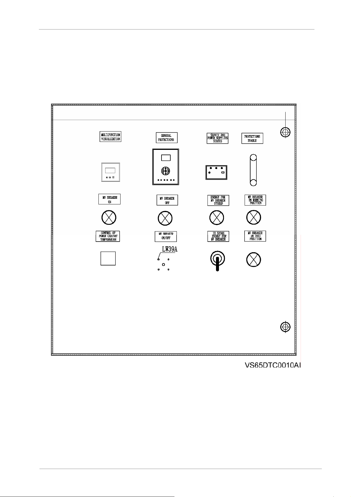
There are several components on the front panel of the power cabinet to control the power-on process of
this cabinet. See the following figure.
VS65
Figure 8.1 Control panel of Power cabinet
ANNEXE A. POWER CABINET OPERATION
41
Page 44

VS65
8.1. Switch Operation of Power Cabinet
The next steps must be followed in order to power-on the power cabinet:
1. Moving the MV breaker from the test position to the working position by the rotating Rocker.
You can hear a “click” sound while the MV breaker is on the working position, after power up you
can find the “MV breaker in working position” lamp is ON.
2. Storing energy for MV breaker.
By the “Store energy for MV breaker “switch, you can turn ON and find the “Energy for MV
breaker stored” lamp is ON.
Note: The store of energy should be available immediately once the switch “Store energy for MV breaker” is
on.
3. MV breaker is closed.
Rotate the “MV breaker ON/OFF” from the “off” left position to the “pre-off” middle position to the
“pre-on” middle position and to the “On” right position. You can find the “MV breaker on” lamp is
ON.
The power-off process of the power cabinet is the following one:
1. MV breaker is opened.
Rotate the “MV breaker ON/OFF” from the “on” right position to the “pre-on” middle position and
to the “pre-off” middle position till the “off” left position. You can find the “MV breaker off” lamp is
ON and the “MV breaker on” lamp is OFF.
2. Moving the MV breaker from the working position to the test position by the rotating Rocker.
If you want to maintenance of the SS, you have to put the MV breaker on the test position to
ensure cut off the MV power.
POWER ELECTRONICS
8.2. Control Panel of Power Cabinet
See figure 8.1 to find out the components referred below.
Safety and Power Supply Status
That is only the indications to the L1, L2, L3 power supply and the power supply of door lock.
Protections Enable
The protection must be always enabled. Do not disconnect it. That is the motor protection.
Control of Power Cabinet Temperature
Parameters Setting of Temperature & Humidity Controller.
Normally, the temperature value is setting at 5°C and the humidity value is setting at 95. If the
measured temperature is lower than 5°C, then one heating resistance will be operated, if the
measured humidity is higher than 95, then another heating resistance will be operated.
Normally, the heating resistance is not operated.
42
ANNEXE A. POWER CABINET OPERATION
Page 45
POWER ELECTRONICS
Multi-function Visualization
Parameters Setting of Multi-function Visualization.
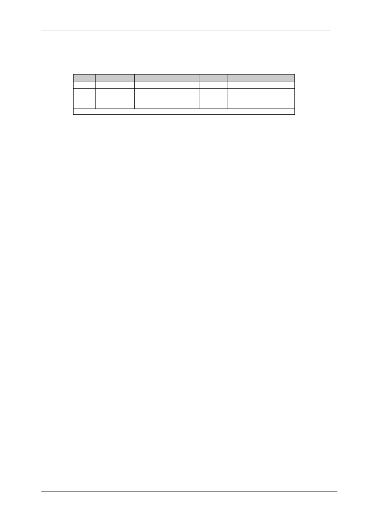
Nº Parameter Description Value Remark
01 In.Pt Voltage ratio 60 Fixed value
02 In.Ct Current ratio 60 Fixed value
03 In.U Secondary Voltage 100V Fixed value
04 In.I Secondary Current 5A Fixed value
Note: The value is only for reference
Since the voltage ratio of the internal voltage transformer is 6000:100 and the current ratio of the
internal current transformer is 300:5, so the primary voltage is 0 - 6000V and then the measured
secondary voltage range is 0 -100V, the primary current is 0 - 300A and then the measured
secondary current range is 0 - 5A.
Note: Normally, all parameters of multi-function visualization are not allowed to be modified by the user
unless the internal hardware is replaced.
General Protections
This device is used to protect asynchronous motors. For further information, please, refer to
section 8.2.1.
VS65
8.2.1. SNP-2371 Asynchronous Motor Protection & Control Unit
The application of SNP-2371 is mainly used for the protection of asynchronous motor at less than
the rated 10kV voltage.
Function and Characteristics
1. Protection function
o Instantaneous over-current (short circuit current and rotor locked current)
o Phase current imbalance (phase loss and phase current imbalance)
o Overload
o Over voltage
o Low voltage
o Zero sequence over current protection ( trip or warn is selectable)
o Zero sequence over voltage protection ( trip or warn is selectable)
o Overheat
2. Assistant Function
o PT (Voltage transformer loop) breaking
o Control loop breaking
o Device fault alarming
o Fault history
o Self-diagnosis
3. Measure and control function
o Measure item: voltage, current, active power, reactive power, power factor, frequency.
o Input: 14 digital inputs
o Control function: controlling one breaker at local or remote.
ANNEXE A. POWER CABINET OPERATION
43
Page 46
VS65
POWER ELECTRONICS
4. Interlocking function
o Interlocking between the local operation and the remote operation.
5. Communication function
o CAN bus and the standard RS485 communication port.
6. Characteristic
o Modular design, it can be assembled or integrated into the switch board.
o Enhanced enclosure, it can resist the electromagnetic interference and can meet the
EMC compliance of IEC.
o Setting protection function by PC with SN-2000 software.
o Recording the events (SOE) and can upload by PC.
8.2.1.1. Basic Principle
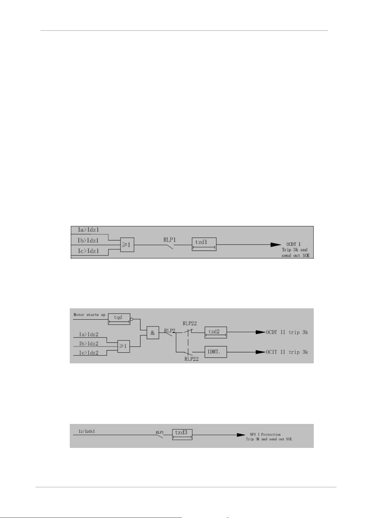
OCDT protection, two stages
The OCDT I is valid after starting the motor and can set a delay time. It is mainly used for the
short-circuit protection of the motor. Any phase current among A, B, C is larger than the setting
protection value and after delay time, the device will trip at once.
Figure 8.2 Logic diagram of OCDT I protection
The OCDT II is used for the rotor locked protection of the motor. It is valid after starting the motor.
The function can prevent from too long starting time and rotor locked. Any phase current among
A, B, C is larger than the setting protection value and after delay time, the device will trip at once.
Figure 8.3 Logic diagram of OCDT II protection
Negative-phase-sequence over current protection
The device provide the NPS I protection to prevent the motor from phase loss, serious voltage
imbalance. The NPS II protection can be used for the more sensitive current imbalance and you
can select the action between warn and trip.
Figure 8.4 Logic diagram of NPS I protection
44
ANNEXE A. POWER CABINET OPERATION
Page 47
POWER ELECTRONICS
Overload protection
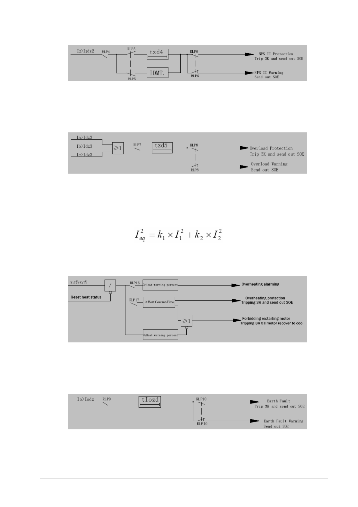
If the current of phase A or phase C (or three phases) is larger than overload setting value, then
the timer is starting. The device can select the action between the warn and trip.
Thermal Overload protection
Thermal overload protection is used to prevent the motor from overheat. Considering the thermal
effect of positive-sequence current (I1) and negative-sequence current (I2), we build a formula as
below to simulate the process of the motor producing (Ieq) heat:
In the start-up time of the motor, K1=0.5 and after the start-up time, K 2=3 ~ 10.
After the device trip, the motor is forbidden to restart until the motor has return to the cool status
or press the “RES” key on the keypad.
Earth fault protection
If the zero sequence current is larger than the setting value, then the timer is starting. The device
can select the action between the warn and trip.
VS65
Figure 8.5 Logic diagram of NPS II protection
Figure 8.6 Logic diagram of Overload protection
Figure 8.7 Logic diagram of Overheat protection
Figure 8.8 Logic diagram of earth fault protection
ANNEXE A. POWER CABINET OPERATION
45
Page 48
VS65
POWER ELECTRONICS
Residual over voltage protection
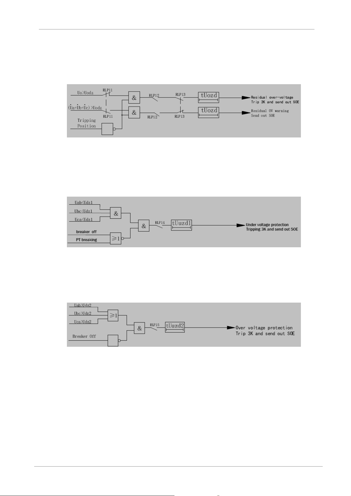
The residual over voltage protection is also used to prevent the stator from the earth fault. If the
zero sequence voltage is larger than the setting value, then the timer is starting. The device can
select the action between the warn and trip.
Figure 8.9 Logic diagram of residual over voltage protection
Under voltage protection
If the line voltage is less than the setting value and the lasting time is longer than the setting time,
the under voltage protection will be operated. The device can automatically detect PT breaking.
Figure 8.10 Logic diagram of under voltage protection
Over voltage protection
If the line voltage is larger than the setting value and the lasting time is longer than the setting
time, the over voltage protection will be operated.
Figure 8.11 Logic diagram of over voltage protection
46
ANNEXE A. POWER CABINET OPERATION
Page 49
POWER ELECTRONICS
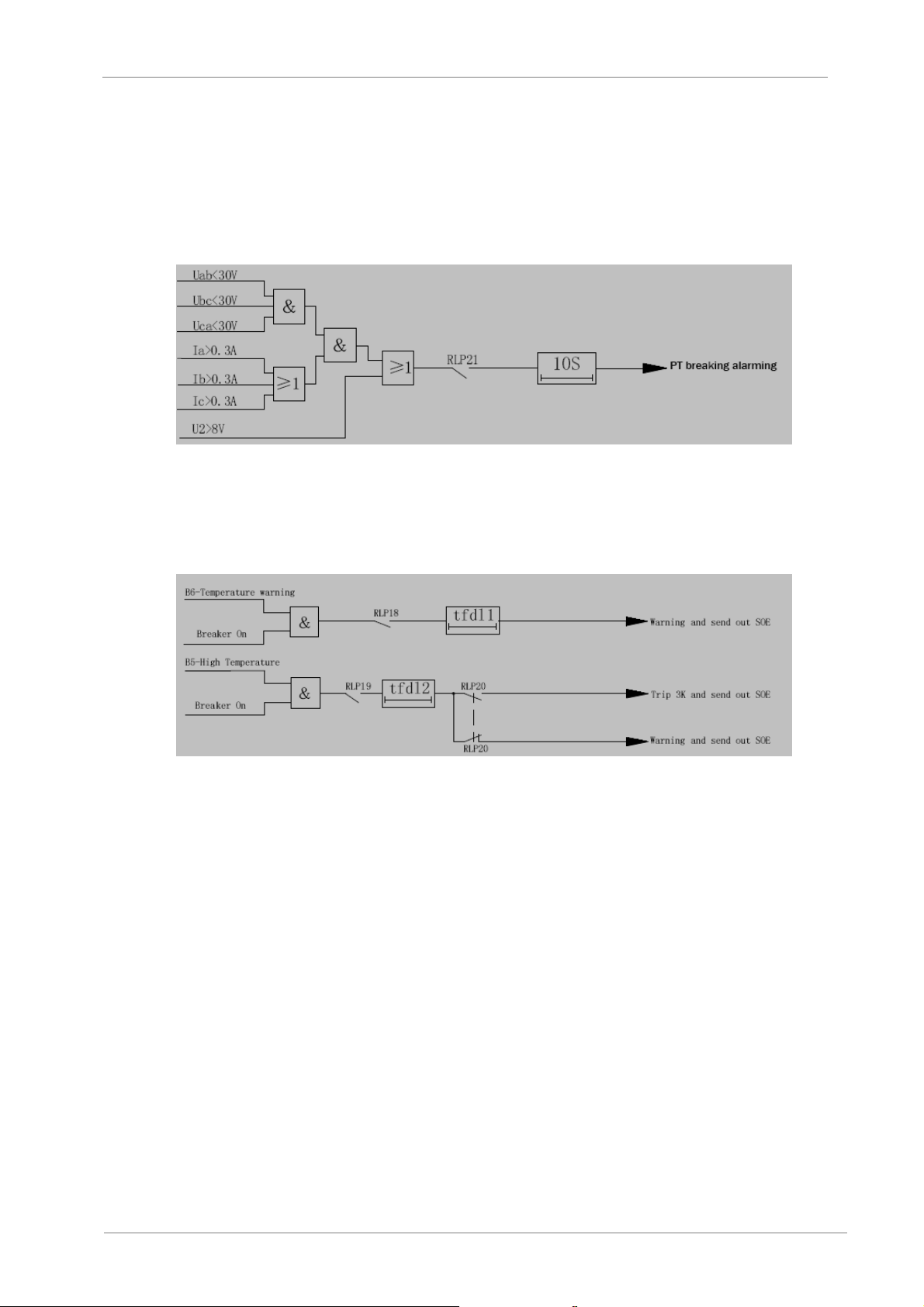
PT breaking protection
The device can detect the PT breaking status. If meet any conditions as below, the device will
send out the warning signal after 10 seconds.
a) The max. phase voltage is less than 30V and any phase current is larger than 0.3 A
b) The negative sequence voltage is larger than 8V.
Non-electric protection
The device can provide two ways of non-electric protection including temperature rising warning
and high temperature trip or warn.
Warning function
Control loop breaking: checking the trip loop while the breaker is ON, and checking the close loop
while the breaker is OFF.
Abnormal status: detecting power loss or self-diagnose error (ROM, RAM, EPROM, etc.)
Measurement
Frequency: f
Voltage: Uab, Ubc, Uca, Ua, Ub, Uc, Uzero
Current: Ia, Ib, Ic, Izero
Power: Active power, reactive power, power factor
Control
You can operate the breaker to trip or close at the remote control or at the manual operation by
the keypad. The interval between two operations must be longer than 10 seconds.
VS65
Figure 8.12 Logic diagram of PT breaking protection
Figure 8.12 Logic diagram of Non-electric protection
ANNEXE A. POWER CABINET OPERATION
47
Page 50

VS65
POWER ELECTRONICS
Record (SOE)
The device can store more than 60 event records, including date, time, fault current, fault voltage,
the protecting action. You can upload them to the supervision system by the communication.
Fault recorder
Record the waveform of current and voltage at fault moment.
8.2.1.2. Operating Instruction
The keypad is consisted of LCD, LED indicators and the keys.
LED indicates the working status and protection signal of device. “24V” indicator light indicates
the device power supply status, if it is normal, the light should be “ON”. “RUN” indicator light
indicates the device is running status, if it is normal, the light should flicker regularly. There are 3
fault lights, the “accident” light and the “alarm” light should indicate the un-rest protection action,
and the “fault” light should indicate the fault after the device self-diagram.
Uab = 10.0kV
I a = 260A
I c = 260A
F = 50.00Hz
When the protection action is occurred or the device is at fault status, the “accident”, “alarm” and
“fault” lights should be “ON”. The type of protection or the relevant fault will be displayed at the
last line.
Note: the displayed content does not mean the sequence which these events occurred. More details, please
select the “Record” item on the main menu to check them.
The monitoring function of device can be achieved by LCD and the keyboard.
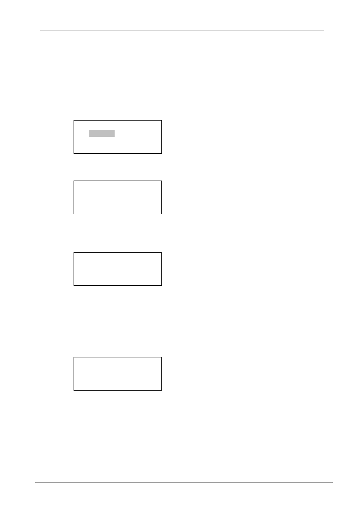
01. Pro ON OFF
02. Set value
03. Record
04. In and Out
05. Sample
06. Time
07. Energy
08. Routine
09. Device
10. Exit
The size of LCD is 16*4 English characters.
The keys are included “↑”, “↓”, “←”, “→”, “Ext”, “enter” and “RES”.
When the device is running normally, the LCD will display all measured information circularly. At
this time you can press “↑”, “↓” to select the expected display items, the display content can be
customized in “Routine” item. If you want to reset protection action or fault signal, you can press
“RES” key and then select the “Y” and “Enter” to confirm it. If you press “←”,”→” or “enter” key,
the main menu will be display as above.
48
ANNEXE A. POWER CABINET OPERATION
Page 51

POWER ELECTRONICS
01 Pro ON OFF
Put the cursor at “Pro ON OFF” and press the “enter” key, then come into the protection function
enable or disable setting as below: (e.g. Line protection)
OCInst
RLP01 ON
OCInst Dir
RLP02 OFF
Put the cursor at “ON/OFF” setting of “OCInst”, you can select the protection items by the key “↑”,
“↓”, then you can change the setting by the key “←”,”→”. After your setting, press the key “enter”
to save these settings.
After pressing the key “enter”, you will come into the PASSWORD setting, as the picture showing
below. You can select the bit you want to modify by the key “←”, “→”. And press the key “↑”, “↓”
will change the value per bit, and the default password is 0000 or 1000. After input the correct
password, the protection setting will be saved.
PASSWORD 1: 0000
02 Set value
Enter into the “Set value” function; you can modify the value on this submenu. There are three
different groups stored in the device, i.e. No.1, No.2 and No.3 groups. The group stored in No.00
is the current group number.
Setting Group
00: 001.00
Voltage ratio
kV1 01: 035.00
By the key “↑” and “↓” to choose the protection item which you want to modify, then press the key
“→” to enter the editing status, you can select the “↑”, “↓”, “←”, “→” keys to modify the setting
value. Press “enter” after modified, and enter the right password, then press the key “enter” again
to make the value into effective. If you press the “exit”, the modification will not be effective. For
further information about set values, see section 8.2.1.3.
Note: the setting voltage value of the PT or the current value of CT will be multiple with 10 times as the
practical measured value on the secondary side.
03 Record
The device can store more than 60 events by the record function. No.0000 is the latest record,
No.0001 is the earlier record. All records are stored in the EEPROM and can be saved after
power off. There are three types of event records, including switch operation, protection operation
and device fault. The display is shown as below:
No. 0000 02-06-26
Time 11:21:22.525
S. Operation
IN 3 OFF-> ON
VS65
ANNEXE A. POWER CABINET OPERATION
49
Page 52
VS65
POWER ELECTRONICS
Remark: the No.0000 is event number, 02-06-26 is the date when the event occurred, that
corresponds to year–month–day.11:21:22.525 is corresponding to hour-minute-secondmillisecond.
By the “↑”, “↓” to display all events. If the type of event is protection operation, press “enter” to
check the operation value, and then press the key “Ext” to return.
04 In and Out
Select the “In and Out” submenu and then display as below:
1. Input
2. Output
By the key “↑”, “↓” to check the input operation or the output operation. When choose the digital
input, the display as below:
Digital Input
01 – 08: 00000010
09 – 16: 00001000
Remark: “0” means that the switch is not closed, “1” means that the switch is closed. In the picture
showed above, the No.7 and No.13 digital inputs are “1”, others are “0”.
Pressing the key “Ext” will return to the previous menu.
When choose the digital output, the display is as show:
Digital Output
FEDCBA9876543210
00000000000000000
By the key “↑”, “↓”, “←”, “→” to select the digital output and modify the output status. The “1” is
closed or the indicator is ON, the “0” is opened or the indicator is OFF. After modifying, you have
to press “enter” and confirm the password, then press “enter” again, the corresponding relay will
be operated.
05 Sample
Select the “Sample” submenu and then the display as below:
0 5.00 5.01
2 56.80 57.02
4 56.87 4.98
6 4.78 5.11
Because the screen only show 4 lines, you can use the key “↑”, “↓” to select the sample data.
Normally, the channel “0” will measure the current of phase A, the channel “1” will measure the
current of phase B, the channel “2” will measure the voltage of phase A, the channel “3” will
measure the voltage of phase B, the channel “4” will measure the voltage of phase C, the channel
“5” will measure the protection current of phase A, the channel “6” will measure the protection
current of phase B, the channel “7” will measure the protection current of phase C. The channels
8 to 12 are different in the different types of device. Please refer to the real time display of
sampling.
50
ANNEXE A. POWER CABINET OPERATION
Page 53
POWER ELECTRONICS
06 Time
The device has a real-time clock that can be running after power off, after entering into the “Time”
submenu and then the display as below:
Date
04Y 06M 26D
Time
15H 36M 50S
You can regulate the real clock by the keypad. Press the “enter” key to enter into an editing
status. And then by the key “↑”, “↓”, “←”, “→” to modify the clock. Press “enter” to make the edit
into effective, or press “Ext” to return.
07 Energy
Choose the item of Energy submenu, and then you can set initial value for pulse energy meter.
This value will change according to the calculation of energy pulses. The device has two routes
input of pulse measurement.
08 Routine
The factory setting value is showed as below and concerned with the secondary transformer
reference. The value is not allowed to be modified by the user.
Nº Code Name Setting Range
0 Kv2 Secondary voltage ratio 11.80 (21)
1 Kic Secondary measured current ratio 235.50 (140)
2 Kib Secondary protective current ratio 14.20 (14.8)
3 Ki0 Secondary zero sequence current ratio 235.20 (14.8)
4 Kv0 Secondary zero sequence voltage ratio 4.75 (14.8)
09 Device
Display the basic information about the device, such as version, type and manufacturer.
VS65
ANNEXE A. POWER CABINET OPERATION
51
Page 54
VS65
POWER ELECTRONICS
8.2.1.3. Miscellaneous Tables
Real time display of sampling
Real time display of sampling
Channel 00 Measure current Ia (C7, D7) Channel 05 Protection current Ia (C9, D9)
Channel 01 Measure current Ic (C8, D8) Channel 06 Protection current Ib (C10, D10)
Channel 02 Busbar voltage Ua (C1, D1) Channel 07 Protection current Ic (C11, D11)
Channel 03 Busbar voltage Ub (C2, D2) Channel 08 Residual current Izero (C12, D12)
Channel 04 Busbar voltage Uc (C3, D3) Channel 09 Residual voltage Uzero (C4, D4)
Set value
Nº Parameter Description Setting Range
00 Setting groups Setting groups 1 – 3
01 kv1 Voltage ratio Real ratio / 10
02 ki1 Current ratio Real ratio / 10
03 Idz1 Current value of over current I 0.1 – 100A
04 tzd1 Delay time of over current I 0 – 100s
05 tqd Motor start-up time 0 – 300s
06 Idz2 Current value of over current II 0.1 -100A
07 tzd2 Delay time of over current II 0 – 100s
08 I2dz1 Current value of NPS I protection 0.1-100A
09 tzd3 Delay time of NPS I protection 0-100s
10 I2dz2 Current value of NPS II protection 0.1-100A
11 Tzd4 Delay time of NPS II protection 0-100s
12 Idz3 Current value of overload protection 0.1-100A
13 Tdz5 Delay time of overload protection 0-100s
14 10zd Current value of earth fault protection 0.1-100A
15 t10zd Delay time of earth fault protection 0-100s
16 U0dz Voltage value of residual voltage protection 3-100V
17 tu0dz Delay time of residual voltage protection 0-100s
18 Udz1 The value of under voltage protection 3-100V
19 tUudz1 Delay time of under voltage protection 0-100s
20 Udz2 The value of over voltage protection 100-140V
21 tUudz2 Delay time of over voltage protection 0-100s
22 k2 Heat factor of negative sequence current I2 0 -10
23 Tfr1 Heating time limited 0.1 – 100min
24 Cool Cooling time limited 0-5
25 GRBJ Heat factor of thermal overload protection 0-100
26 Tfd11 Delay time of temperature rise protection 0-100s
27 Tfd12 Delay time for Hi-temperature protection 0 -100min
28 Ie Rated motor current 1 – 6A
52
ANNEXE A. POWER CABINET OPERATION
Page 55
POWER ELECTRONICS
Pro ON OFF
Nº Code Parameter Description
01 RLP01 OCDTI Over current I protection
02 RLP02 OCDTII Over current II protection
03 RLP03 NPS I
04 RLP04 NPS II
05 RLP05 NPSIT II
06 RLP06 NPSIT II Trip
07 RLP07 Overload Overload protection
08 RLP08 Overload Trip Trip or warn of overload protection
09 RLP09 Earth Fault Earth Fault protection
10 RLP10 Earth Fault Trip Trip or warn of Earth Fault protection
11 RLP11 Calculation RV Calculating residual voltage
12 RLP12 Residual OV Residual over voltage protection
13 RLP13 Residual OV Trip
14 RLP14 Under Voltage Under voltage protection
15 RLP15 Over Voltage Over voltage protection
16 RLP16 Thermal-overload warn Warn of overheat protection
17 RLP17 Thermal-overload trip Trip of overheat protection
18 RLP18 Temperature Temperature rising protection
19 RLP19 Hi- temperature Hi-temperature protection
20 RLP20 Hi- temperature Trip Trip or warn of Hi-temperature protection
21 RLP21
22 RLP22 OCIT II Inverse time of over current II protection
32 RLP32 DRec
Record
Bit Parameter Description Bit Parameter Description
D0 OCDT I
D1 OCDT II
D2 NPS I
D3 NPS II
D4 Overload Overload protection D12 Hi- temperature Hi- temperature
D5 Earth Fault Earth Fault warning D13 PT Breaking PT breaking warning
D6 Residual OV Residual over voltage D14 Reserved Reserved
Ctrl-Loop-
D7
Break
PT (Voltage transformer)
breaking
Over current I
protection
Over current II
protection
Negative phase
sequence over current
I protection
Negative phase
sequence over current
II protection
Control loop breaking D15
D8 Under Voltage Under Voltage
D9 Over Voltage Over Voltage
D10
D11
Negative phase sequence over current I
protection
Negative phase sequence over current II
protection
Inverse time of Negative phase sequence
II protection
Trip or warn of Negative phase sequence
II protection
Trip or warn of residual over voltage
protection
PT breaking warning
Record A and V wave when the fault
occurred
Thermaloverload
Temperature
rising
Thermal
Overload Trip
Thermal overload
Temperature rising
Thermal overload
tripping
VS65
ANNEXE A. POWER CABINET OPERATION
53
Page 56

VS65
POWER ELECTRONICS
9. ANNEXE B. ELECTRICAL AND MECHANICAL
DRAWINGS
Next, electrical and mechanical drawings are attached in the following pages.
54
ANNEXE B. ELECTRICAL AND MECHANICAL DRAWINGS
Page 57
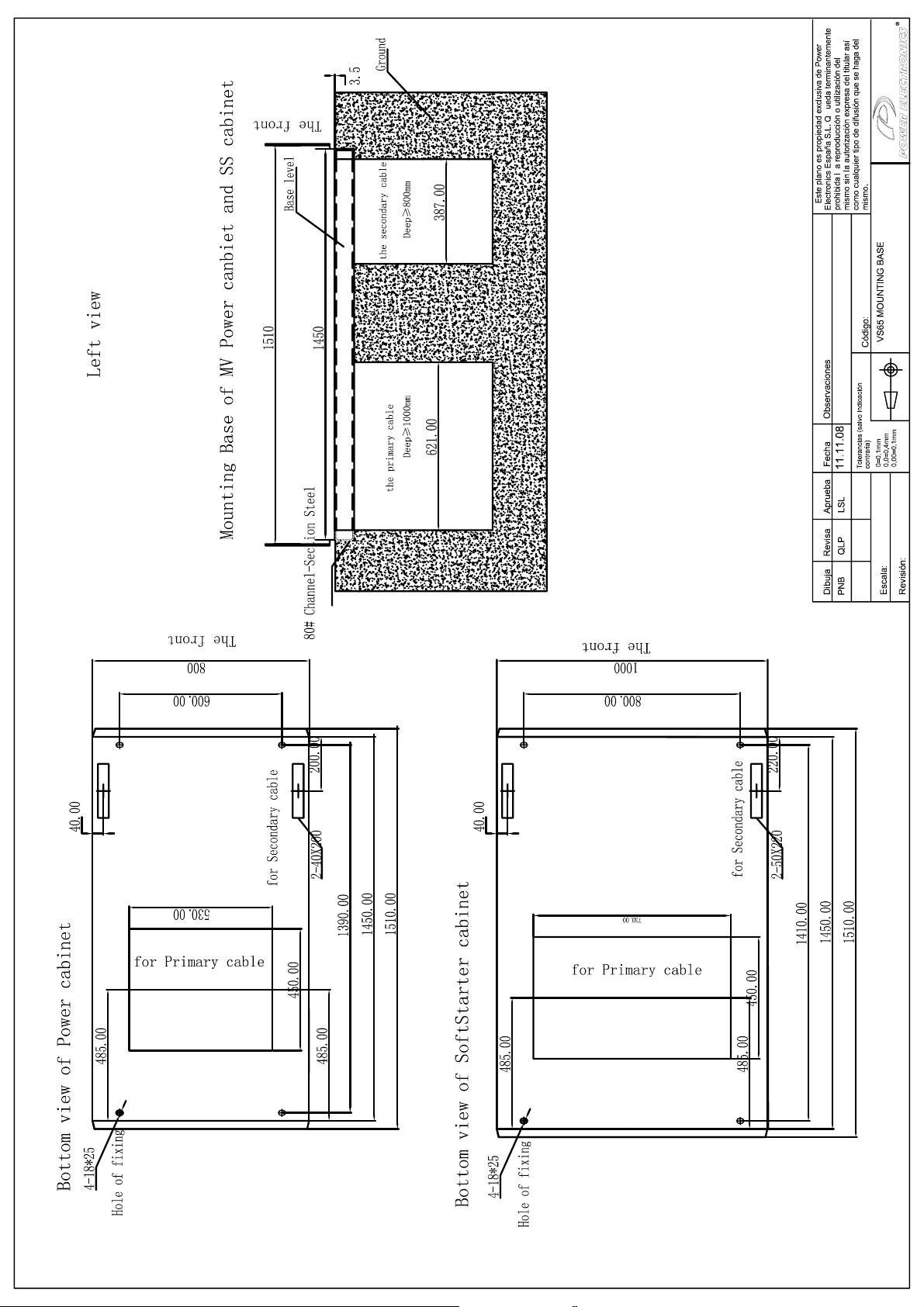
Page 58
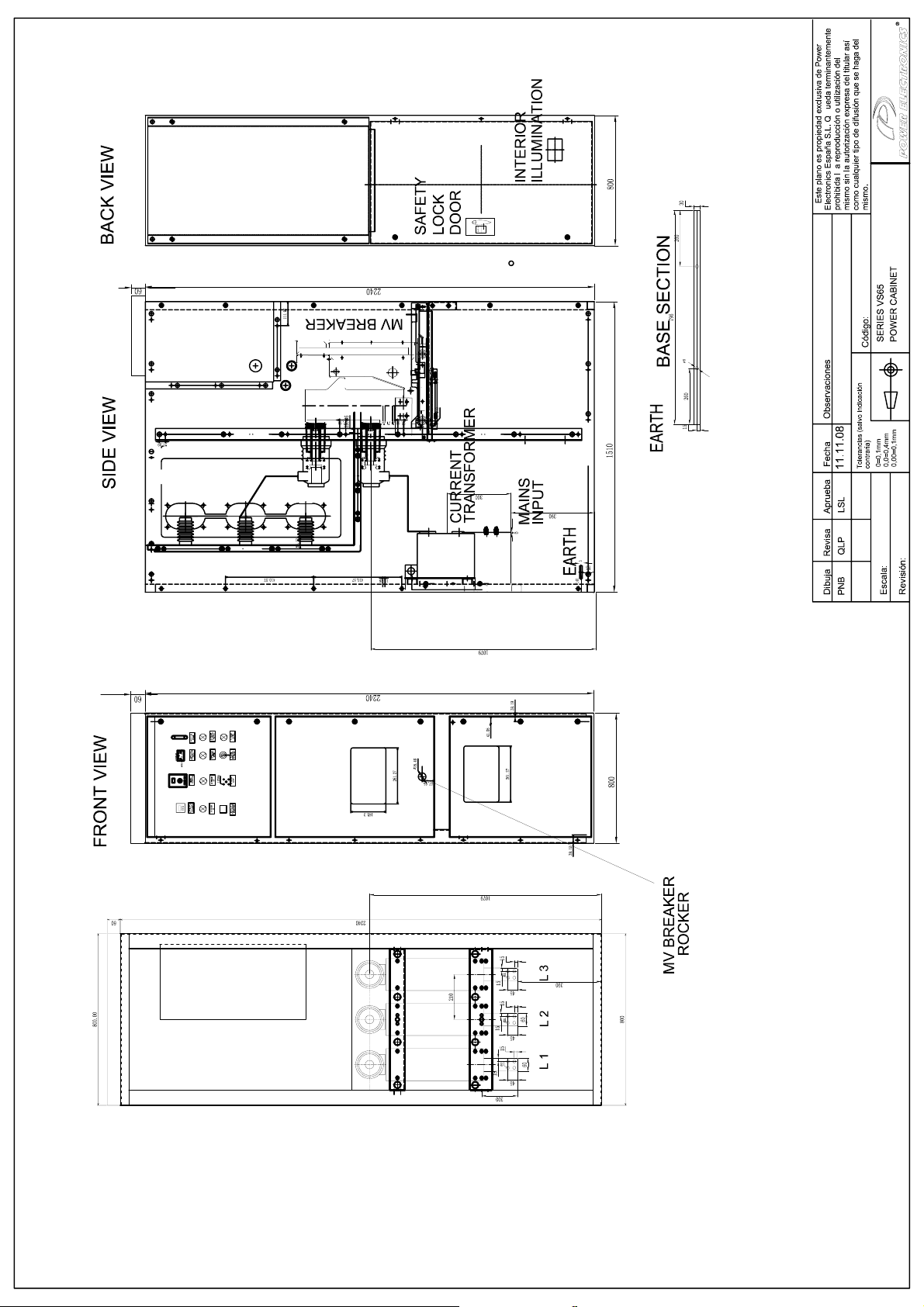
Page 59
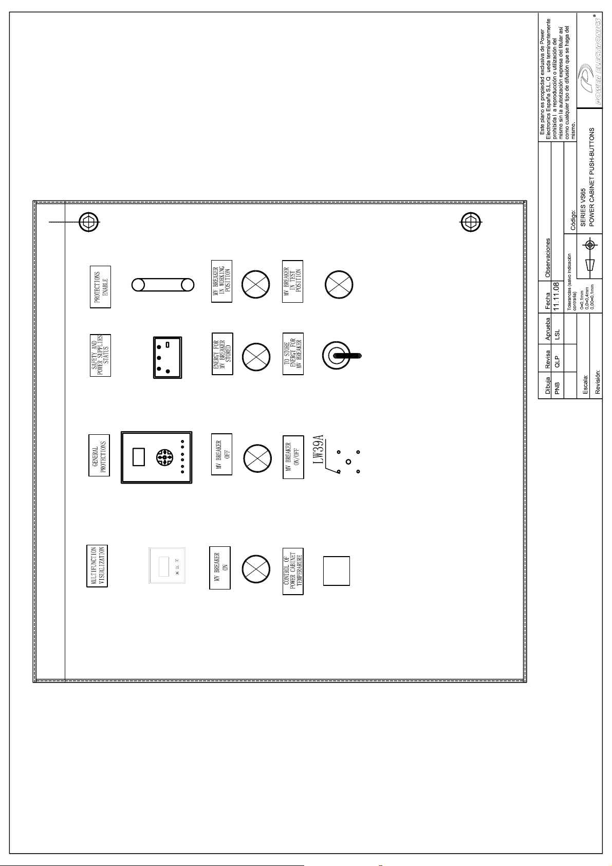
Page 60
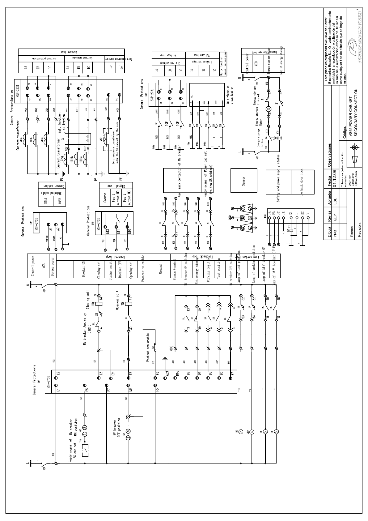
Page 61
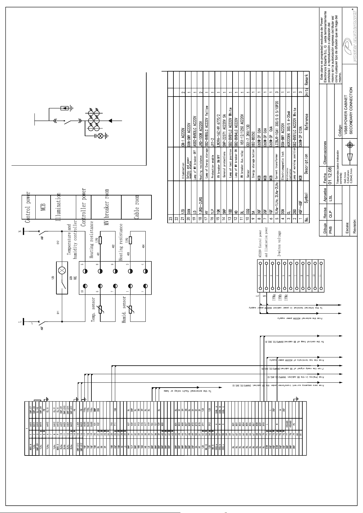
Page 62
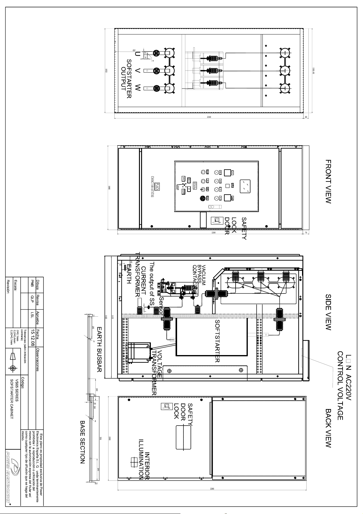
Page 63
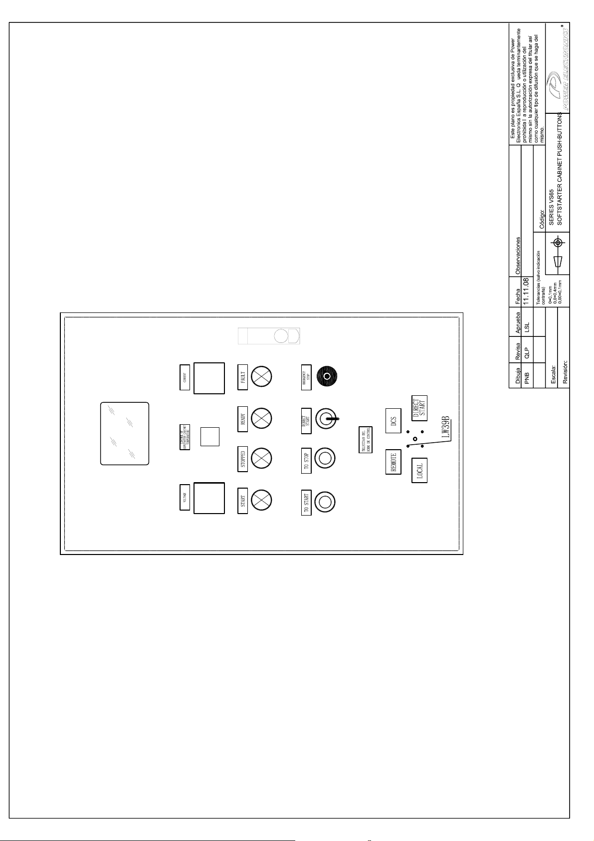
Page 64
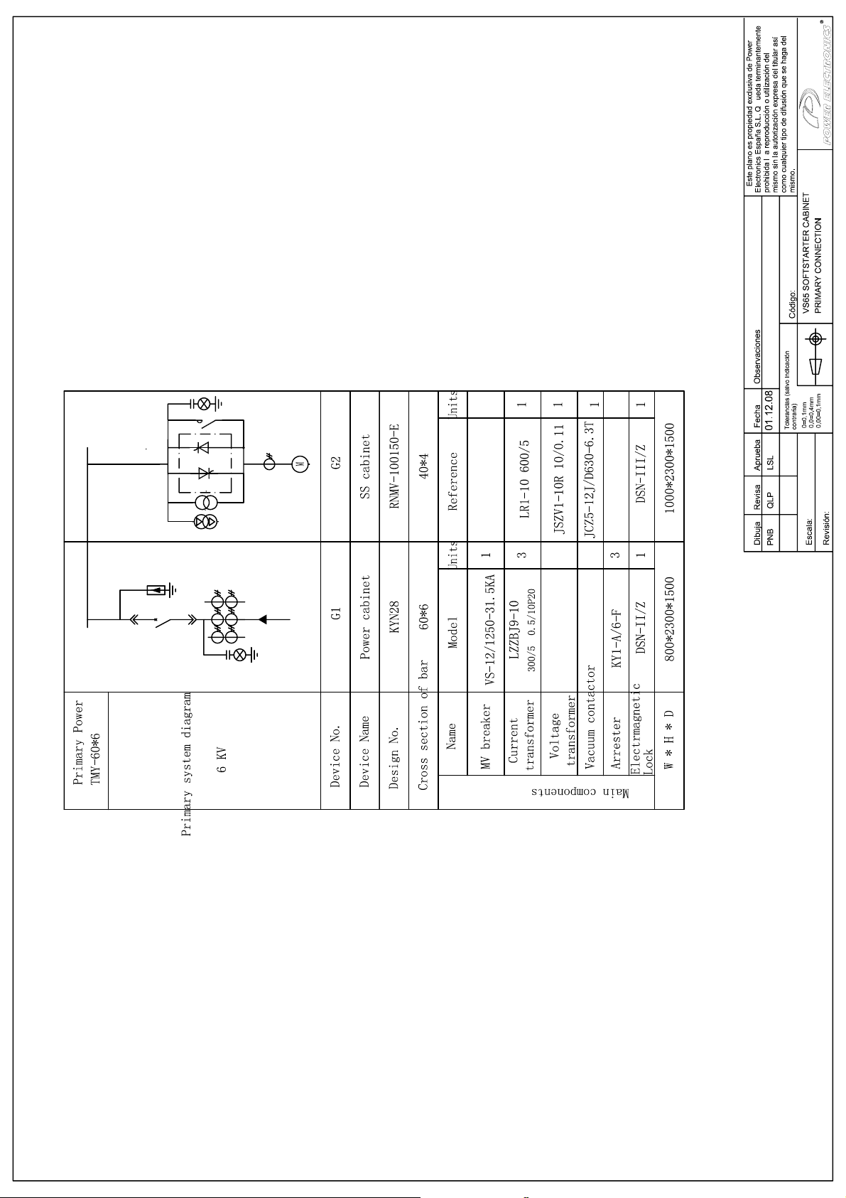
Page 65
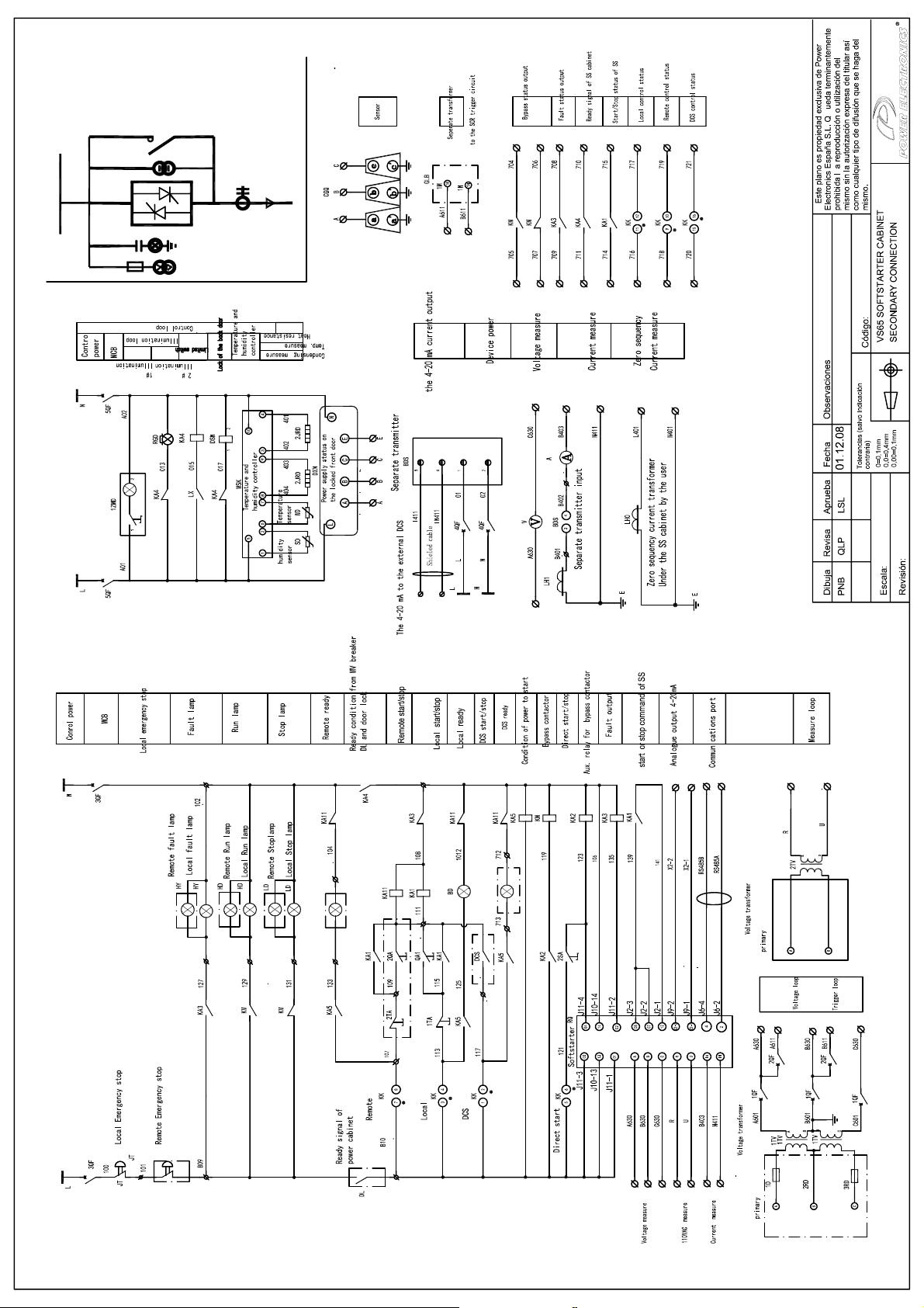
Page 66
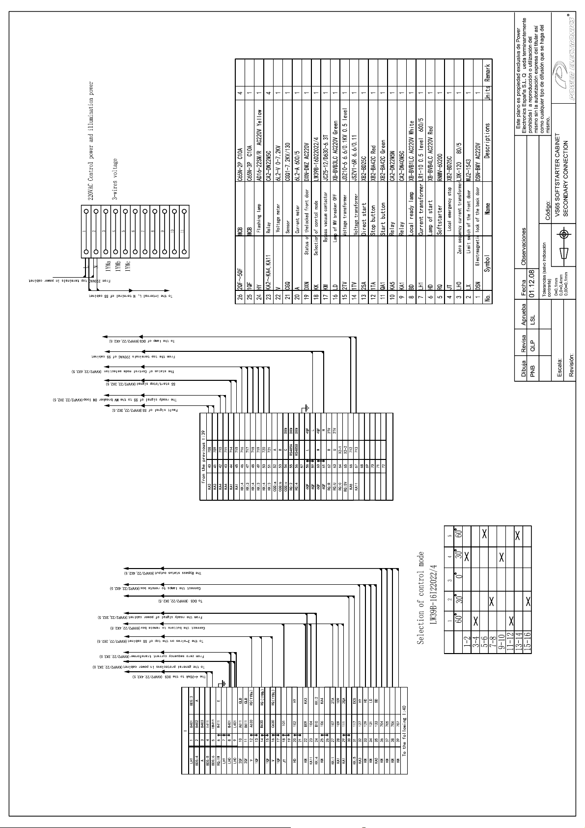
Page 67
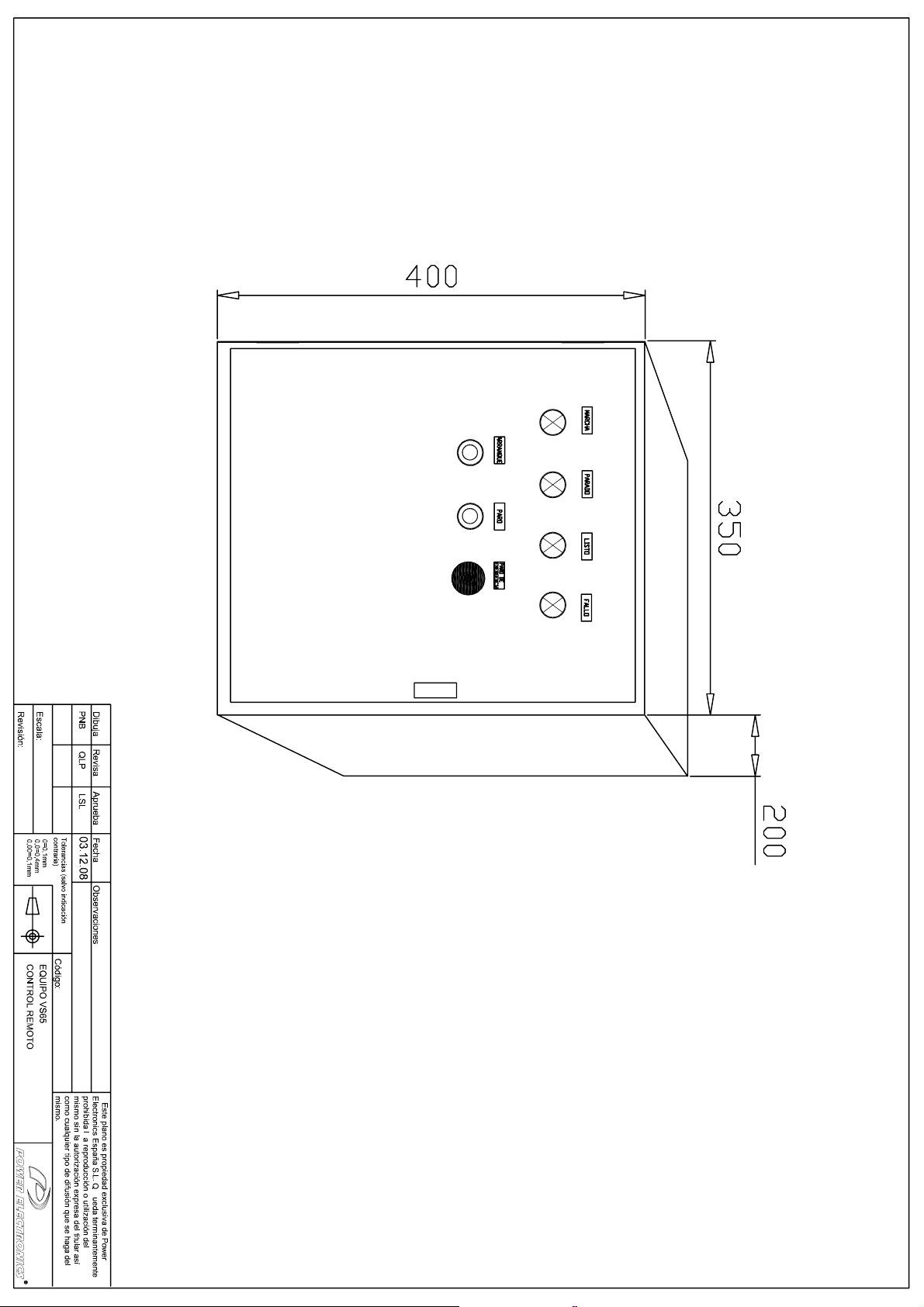
Page 68
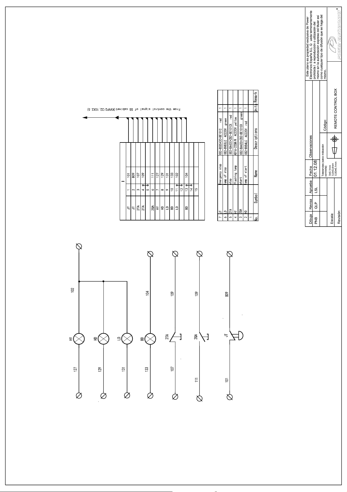
Page 69
3J
3J
$
0<D
,,
,,,,,
%
&
/
1
;$;$;$;$;$;$;$;$;$;$;$
<0E
<0F
/
1
;3;3;3;3;3;3;3;3;3;3;3
,,,,
$50$5,2
5(*/(7(52
$55$1&$'25
3$1(/)5217$/
PPß
$50$5,2
5(*/(7(52
$55$1&$'25
$50$5,2
327(1&,$
5(*/(7(52
1(*52
7(&+2
7(&+2
;$;$;$;$
PPß
1(*52
/
1
;3;3;3;3
966(5,(
96
%
%
$50$5,2
$55$1&$'25
96,17(5&21(;,Â1
327(1&,$$55$1&$'25
%
%
PPß
1(*52
$50$5,2
327(1&,$
/
1
0<D
<0E
<0F
/
,,,,,,,
,,
/
$50$5,2
327(1&,$
5(*/(7(52
1
1
%
%
,17(5&21(;,Â196
9
3$1(/)5217$/
9$
/6/
$
'LF
(1$55$1&$'25
6($/$50$5,2
6($/$50$5,2
327(1&,$/,672
$55$1&$'25/,672
680,1,6752&/,(17(
92/7$*(75$16)250(5
75$16)250$'25&255,(17(
6(&8(1&,$&(52$55$1&$'25
)HFKD'DWH
&RPSUREDGR&KHFNHG
(ODERUDGR'UDZQ
&DPELRV&KDQJHV
Page 70

Page 71

www.power-electronics.com
24 Hours Technical Assistance 365 days a year 902 40 20 70
HEAD OFFICE C/ Leonardo da Vinci, 24 - 26, Parque Tecnológico · 46980 · Paterna · VALENCIA
INTERNATIONAL
BRANCHES:
AUSTRALIA Power Electronics Australia Pty Ltd
CHILE Power Electronics Chile Ltda
CHINA Power Electronics Beijing
GERMANY Power Electronics Deutschland GmbH
INDIA Power Electronics India
KOREA Power Electronics Asia HQ Co.
MEXICO P.E. Internacional México S de RL de CV
Tel. (+34) 96 136 65 57 · Fax. (+34) 96 131 82 01
U6, 30-34 Octal St, Yatala, Brisbane, Queensland 4207 · P.O. Box 3166
Browns Plains · Queensland 4118 · AUSTRALIA
Tel. (+61) 7 3386 1993 · Fax. (+61) 7 3386 1997
Los Productores #4439 · Huechuraba
Santiago · CHILE
Tel. (+56) (2) 244 0308 / 0327 / 0335 · Fax. (+56) (2) 244 0395
Room 310, Estoril House No. 2, JiangTai Road
100016 · ChaoYang District
Beijing · P.R. CHINA
Tel. (+86 10) 6437 9196 / 97 · Fax (+86 10) 6437 9181
Conradtystrasse, 41 · D-902441 · NÜRNBERG · GERMANY
Tel. (+49) 911 99 43 99 0 · Fax (+49) 911 99 43 99 8
No. 26, 3rd Cross, Vishwanathapuram
625014 Madurai · INDIA
Tel. (+91) 452 434 7348 · Fax (+91) 452 434 7348
Room #305, SK Hub Primo Building 953-1, Dokok-dong, Gangnam-gu
SEOUL · 135-270 KOREA
Tel. (+82) 2 3462 4656 · Fax (+82) 2 3462 4657
Luz Savión, 205, Colonia del Valle
03100 México D. F. · MEXICO
Page 72

POWER ELECTRONICS reserves the right to modify whole or part of the content of this document at any time and without prior notice. November 2008.
 Loading...