

Page 1
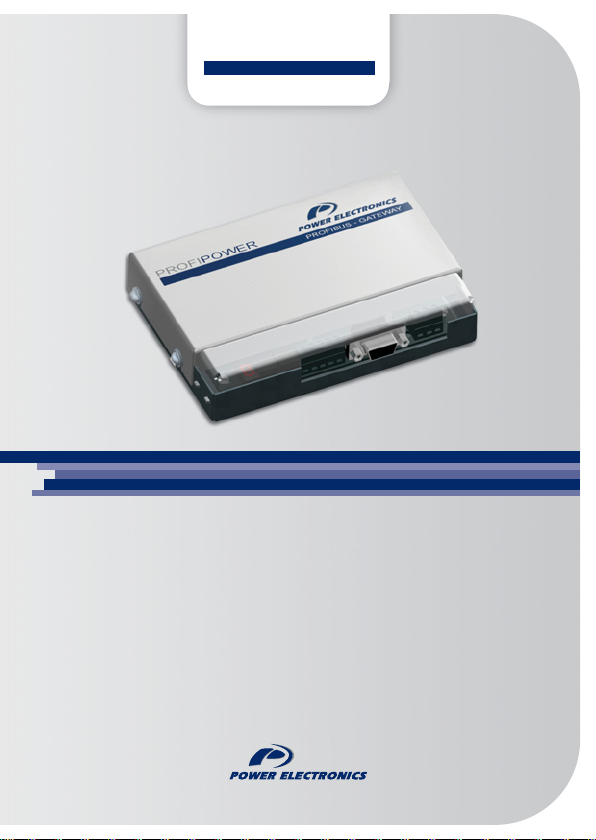
PROFIPOWER
PROFIBUS - GATEWAY
profibus gateway
Communication Network
Page 2

Page 3

modbus – profibus gateway
Communication Network
Edition: June 2007
GBC02CI Rev. C
Page 4

PROFIPOWER POWER ELECTRONICS
2
Page 5
POWER ELECTRONICS PROFIPOWER
SAFETY SYMBOLS
Always follow safety instructions to prevent accidents and potential hazards
from occurring.
This symbol means improper operation may results in
serious personal injury or death.
Identifies shock hazards under certain conditions.
Particular attention should be given because dangerous
voltage may be present. Maintenance operation should be
done by qualified personnel.
Edition of June 2007
This publication could present technical imprecision or misprints. The
information here included will be periodically modified and updated, and all
those modifications will be incorporated in later editions.
To consult the most updated information of this product you might access
through our website
www.power-electronics.com where the latest version of
this manual can be downloaded.
Revisions
Date Revision Description
16 / 06 /2006 A Software version Profipower 1.0
31 / 10 /2006 B Wiring updating for SD700 and V5
13 / 06 /2007 C Misprints update
SAFETY SYMBOLS
3
Page 6

PROFIPOWER POWER ELECTRONICS
4
Page 7

POWER ELECTRONICS PROFIPOWER
INDEX
SAFETY INSTRUCTIONS..............................................................................7
1. INTRODUCTION ....................................................................................10
1.1. Equipment Description...............................................................10
2. TECHNICAL CHARACTERISTICS ........................................................11
2.1. General Information...................................................................11
2.2. Dimensions................................................................................12
3. INSTALLATION AND CONNECTION....................................................13
3.1. Installation of Profipower Gateway............................................. 13
3.2. Connections of Profipower Gateway..........................................14
3.3. Setting of Profibus Address........................................................23
3.4. Display and Faults Code............................................................24
4. TRIAL RUN............................................................................................26
4.1. Introduction................................................................................26
4.2. Trial Run with Siemens (Step 7 Set-up).....................................31
4.3. Configuration and Set up ...........................................................33
5. PROGRAMMING FOR STEP 7..............................................................43
5.1. Example of program for Step 7..................................................44
5.2. Monitoring and Modification of Modbus Registers......................45
6. DIAGNOSIS............................................................................................46
INDEX
5
Page 8

PROFIPOWER POWER ELECTRONICS
6
INDEX
Page 9
POWER ELECTRONICS PROFIPOWER
SAFETY INSTRUCTIONS
IMPORTANT!
Safety instructions showed in this manual are useful to teach user
how to use the product in a correct and safety way with the purpose
of preventing possible personal injuries or property damages.
Safety messages included here are classified as it follows:
WARNING
Do not remove the cover while the power is applied or the unit is in
operation.
Otherwise, electric shock could occur.
Do not run the inverter with the front cover removed.
Otherwise, you may get an electric shock due to the high voltage
terminals or exposure of charged capacitors.
Do not remove the cover except for periodic inspections or wiring,
even if the input power is not applied.
Otherwise, you may access the charged circuits and get an electric shock.
Wiring and periodic inspections should be performed at least 10
minutes after the equipment that is going to be connected to this
gateway is disconnected from the input power and after checking
the DC Link voltage is discharged with a meter (below 30VDC).
Otherwise, you may get an electric shock.
Operate the switches with dry hands.
Otherwise, you may get an electric shock.
Do not use cables with damaged insulation.
Otherwise, you may get an electric shock.
Do not subject the cables to the abrasions, excessive stress, heavy
loads or pinching.
Otherwise, you may get an electric shock.
SAFETY INSTRUCTIONS
7
Page 10
PROFIPOWER POWER ELECTRONICS
CAUTION
Do not allow lint, paper, wood chips, dust, metallic chips or other
foreign matter into the gateway.
Otherwise, fire or accident could occur.
WARNINGS
RECEPTION
Material of Power Electronics is carefully tested and perfectly
packed before leaving the factory.
In the even of transport damage, please ensure that you notify
the transport agency and POWER ELECTRONICS: 902 40 20 70
(International +34 96 136 65 57) or your nearest agent, within
24hrs from receipt of the goods.
UNPACKING
Make sure received merchandise corresponds with delivery note,
models and serial numbers.
Each gateway is supplied with a technical manual.
SAFETY INSTRUCTIONS
8
Page 11

POWER ELECTRONICS PROFIPOWER
SAFETY
Before operating the equipment, read this manual thoroughly to
gain and understanding of the unit. If any doubt exists then
please contact POWER ELECTRONICS, (902 40 20 70 / +34 96
136 65 57) or your nearest agent.
Wear safety glasses when operating the equipment with power
applied and the front cover is removed.
Install the inverter according to the instructions within this
manual.
Ensure that the mounting orientation is correct.
Do not drop the gateway or subject it to impact.
The Profipower gateways contain static sensitive printed circuits
boards. Use static safety procedures when handling these
boards.
CONNECTION PRECAUTIONS
To ensure correct operation of the equipment it is recommended
to use a SCREENED CABLE for the control wiring.
TRIAL RUN
Follow the steps described in this manual.
Always apply voltage and current signals to each terminal that
are within levels indicated within this manual. Otherwise, damage
to the gateway may result.
SAFETY INSTRUCTIONS
9
Page 12
PROFIPOWER POWER ELECTRONICS
1. INTRODUCTION
1.1. Equipment Description
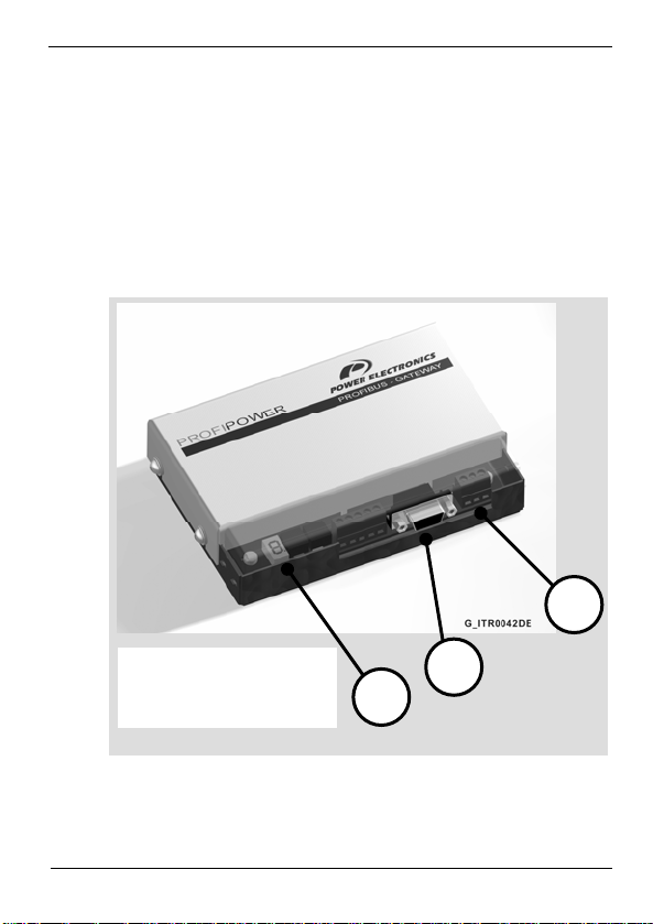
The Profipower gateway allows integrating all of the equipments of
Power Electronics into Profibus networks easily and comfortably.
Its useful design will allow you to know the operating status of the
gateway all the time.
1
1. Power supply connector
2. Communication connector
3. Status visualization
INTRODUCTION
10
2
3
Page 13

POWER ELECTRONICS PROFIPOWER
2. TECHNICAL CHARACTERISTICS
2.1. General Information
2.1.1. Interfaces
Profibus-DP Connector 9 Pin D-SUB / F.
Voltage terminals 3 wires.
RS232 terminals 3 wires.
2.1.2. Power Supply Source
Rated value 24 Vdc.
Allowed range (curly included) 18 to 28Vdc.
Maximum Consumption 130mA.
+24V Limitation to 130mA.
2.1.3. Electrical Insulation
Profibus – DP / RS232 connection 500Vac.
2.1.4. Local Indications
ON Led (Green): If it is lit indicates operative voltage. The gateway
is power supplied.
FAULT Led (Red): If it is lit indicates gateway fault.
7 segments display: it indicates the status of the gateway.
TECHNICAL CHARACTERISTICS
11
Page 14
PROFIPOWER POWER ELECTRONICS
2.1.5. Profibus-DP Interface
Profibus – DP Interface.
Transmission speed Auto-detected at 12Mb.
Diagnosis data length of 13 Bytes (maximum).
Data length of Set up of 176 Bytes (maximum).
Configuration data length of 8 Byte (maximum).
Polling length of 120 Bytes (maximum).
File GSD PWE_05DD.GSD.
2.2. Dimensions
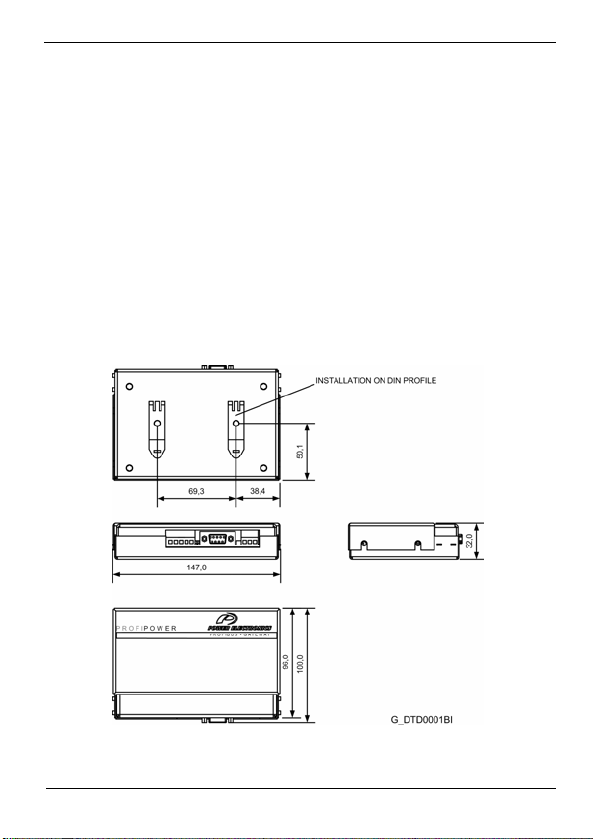
External dimensions of Profipower gateway can be observed in the
attached figure. The device is ready to be installed on Din profile.
Figure 2.1 Profipower dimensions. Modbus – Profibus gateway
TECHNICAL CHARACTERISTICS
12
Page 15
POWER ELECTRONICS PROFIPOWER
3. INSTALLATION AND CONNECTION
3.1. Installation of Profipower Gateway
The Profipower gateway of Power Electronics is a module to connect
the inverters and soft starters of Power Electronics to a PROFIBUS
network directly. It is necessary to use one gateway for each
equipment to connect it to the network.
Note: Gateway installation does not involve that the inverter or soft
starter and/or the power is configured or connected in a correct way
respectively. Make sure the peripheral installation is well done to
guarantee a correct operation of the system.
CAUTION
Motor controllers of Power Electronics operate with a high electric
energy.
Make sure the power supply has been disconnected and wait for at least
10 minutes to guarantee that DC Link voltage is discharged, before
installing the interface module of Profibus. Otherwise, you may get
personal injuries or an accident could occur.
The gateway should be installed near to the motor controller. The
maximum distance between the motor controller and the gateway
should be of 3 meters, but only if it is necessary.
INSTALLATION AND CONNECTION
13
Page 16
PROFIPOWER POWER ELECTRONICS
3.2. Connections of Profipower Gateway
3.2.1. Description of terminals and Leds
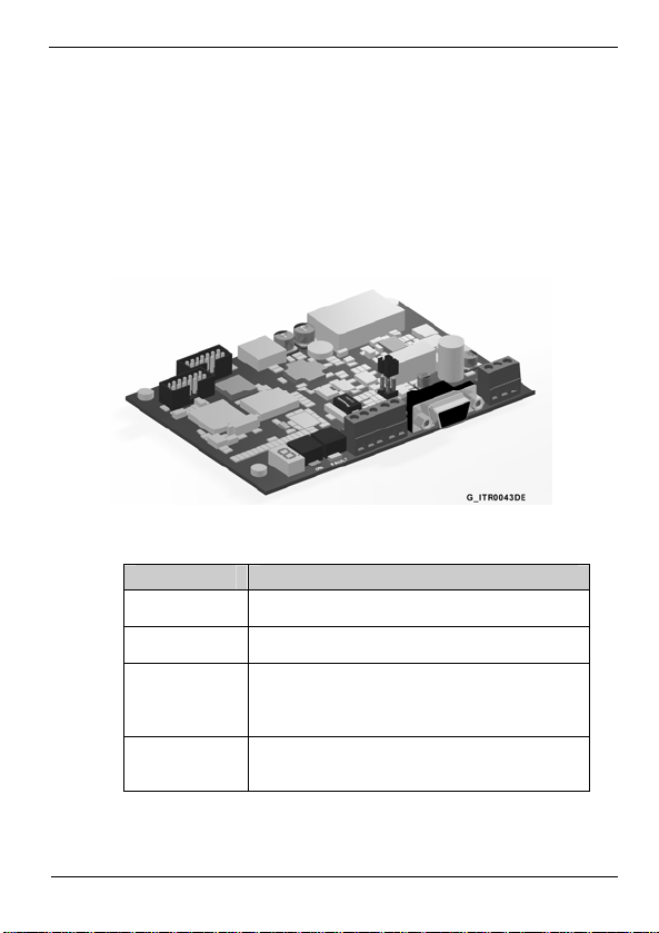
In the Profipower gateway, it exist different connectors to install this
gateway and to connect it to the variable speed drives and digital
soft-starters of Power Electronics.
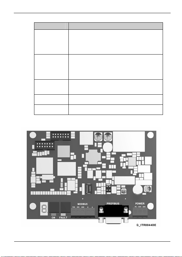
Figure 3.1 Location of the connectors of the Profipower interface
TERMINALS DESCRIPTION
U109
J201
(PROFIBUS)
JP203
(MODBUS)
JP204
(MODBUS)
7 segments display. It shows the operation status of the
Profipower gateway.
Connector SUB-D 9 pins to connect the signals of the
Profibus network.
RS232 port to connect Modbus signals.
1: TxD signal
2: RxD signal
GND: Common for communications
RS485 port to connect Modbus signals.
B: High Signal (+)
A: Low Signal (-)
INSTALLATION AND CONNECTION
14
Page 17
POWER ELECTRONICS PROFIPOWER
TERMINALS DESCRIPTION
Connector for the signals of the gateway power supply.
Power supply connection of 24Vdc.
J301 (POWER) +24V: Positive of the power supply source.
GND: Negative of the power supply source.
PE: Ground
To connect the ending resistors of the network. If it is
not necessary to enable the ending resistor of the
J1 (Jumper 1)
network, the jumper will be not connected. Otherwise,
the jumper will be connected and so these resistors will
be enabled.
Rotary selectors to adjust the addresses in
U107, U108
ON Led
FAULT Led
Hexadecimal. Selectors are on the right-hand side of
the 7 segments display.
Green. If it is lit indicates that the gateway is power
supplied.
Red. If it is lit indicates that the gateway is in fault
status.
You can observe the above mentioned terminals below:
Figure 3.2 Description of the Profipower interface terminals
INSTALLATION AND CONNECTION
15
Page 18
PROFIPOWER POWER ELECTRONICS
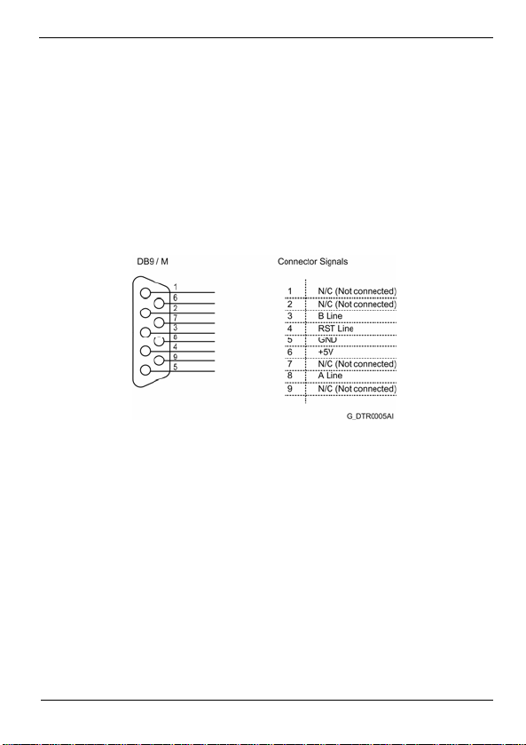
3.2.2. Profibus Connections
For profibus connection, a standard connector SUB-D 9 pins is used
according to the definition of the standard EN 50170. The wiring for the
connector of nine pins is shown in the attached figure.
If additionally, more information is required, refer to “Installation Guide
of PROFIBUS DP/FMS" of the profibus users group, where you can
find more detailed information about the connection.
16
Figure 3.3 Connections of the connector SUB-D 9 pins
INSTALLATION AND CONNECTION
Page 19
POWER ELECTRONICS PROFIPOWER
3.2.3. Connection for Equipments of Power Electronics
3.2.3.1. Variable Speed Drives of SD250 Series
Use S+ terminal to connect RS485 high signal and use S- terminal
to connect RS485 low signal.
RS485 communication data:
Transmission form: Bus method, Multi drop Link System.
Applicable drives: SD250.
Converter: RS232 converter.
Connectable drives: Maximum 31.
Transmission distance: Below 1.200m maximum (700m recommended).
Recommended cable: 0.75mm² (18AWG), Shield type twisted-pare.
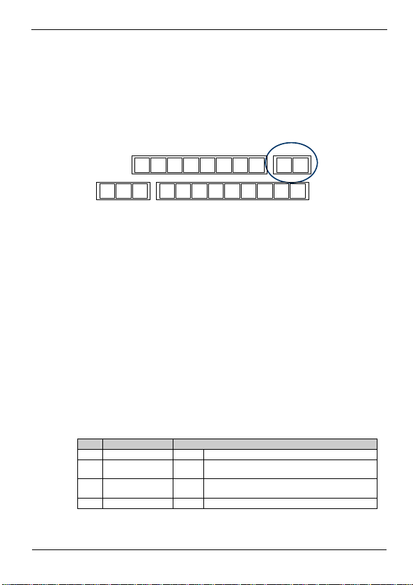
Installation: S+ and S- terminals of TB1 connector located on control board.
Power supply: Power supply insulated from the drive power supply.
After connecting the communication line, set the following
parameters as follows:
Par. Description Setting
drv Drive mode 3 RS485 communication.
Frq Frequency setting
I60 Slave No. in
I61 Transmission speed 3 9.600bps; factory setting.
TB3 TB1
TB4TB2
P5 CM P6 P7 P8 VR V1 I AM3A 3C 3B
Figure 3.4 TB1 connector of the control board
mode
communic. network
7 RS485 communication.
Use different numbers in case of more than 1 inverter is
1 – 250
installed.
P4MO MG 24 P1 P2 CM P3 S+S-
SD25DTC0005AE
INSTALLATION AND CONNECTION
17
Page 20
PROFIPOWER POWER ELECTRONICS
Par. Description Setting
I62 Stop mode after
signal loss
I63 Time to determ.
signal loss
I59 Communication
protocol
0 Non stop. Factory setting.
1.0sec Factory setting.
0 0: Modbus RTU
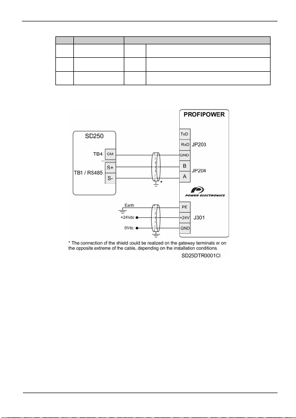
Connection drawing:
Figure 3.5 Connection of SD250 – Profipower gateway
INSTALLATION AND CONNECTION
18
Page 21
POWER ELECTRONICS PROFIPOWER
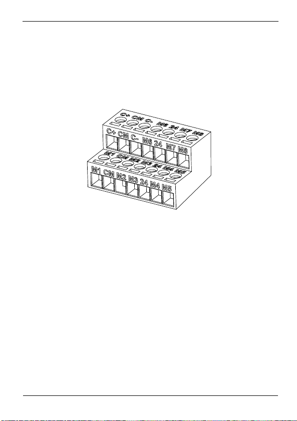
3.2.3.2. Variable Speed Drives of SD450 Series
Use C+ terminal to connect the RS485 high signal and C- terminal to
connect the RS485 low signal.
Ground will be connected to the CM terminal. All of these terminals
are located in the connector of the figure.
Figure 3.6 TER2 connector of control board
RS485 communication data:
Transmission form: Bus method, Multi drop Link System.
Applicable drives: SD450.
Connectable drives: Maximum 31.
Transmission distance: Below 1200m maximum (700m recommended).
Recommended cable: 0.75mm² (18AWG), shield type twisted-pare.
Installation: C+, C- and CM terminals.
Power supply: Power supply insulated from the drive power supply.
SD45DTC0012AE
INSTALLATION AND CONNECTION
19
Page 22
PROFIPOWER POWER ELECTRONICS
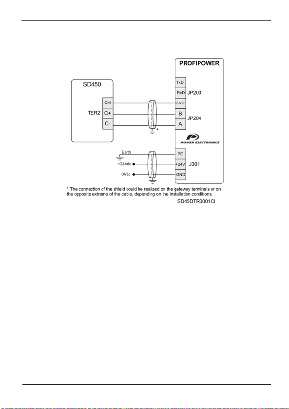
Connection drawing:
Figure 3.7 Connection of SD450 – Profipower gateway
INSTALLATION AND CONNECTION
20
Page 23
POWER ELECTRONICS PROFIPOWER
3.2.3.3. Variable Speed Drives of SD700 Series
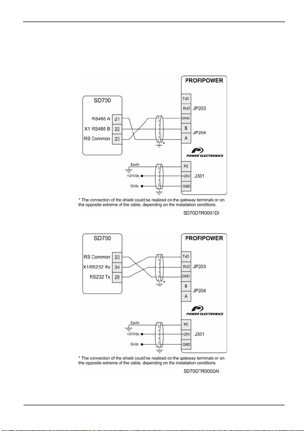
Connection drawing:
Figure 3.8 Connection of SD700 – Profipower gateway RS485 port
Figure 3.9 Connection of SD700 – Profipower gateway RS232 port
INSTALLATION AND CONNECTION
21
Page 24
PROFIPOWER POWER ELECTRONICS
3.2.3.4. Digital Soft-Starter V5 Series
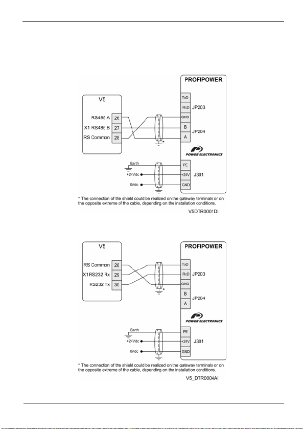
Connection drawing:
Figure 3.10 Connection of V5 – Profipower gateway RS485 port
Figure 3.11 Connection of V5 – Profipower gateway RS232 port
INSTALLATION AND CONNECTION
22
Page 25
POWER ELECTRONICS PROFIPOWER
3.3. Setting of Profibus Address
Two rotary selectors are used to adjust the Profibus address of the
gateway. Through these selectors, we obtain a hexadecimal reading of
the device address.
The range of the valid addresses goes from 1 to 125. That is, from
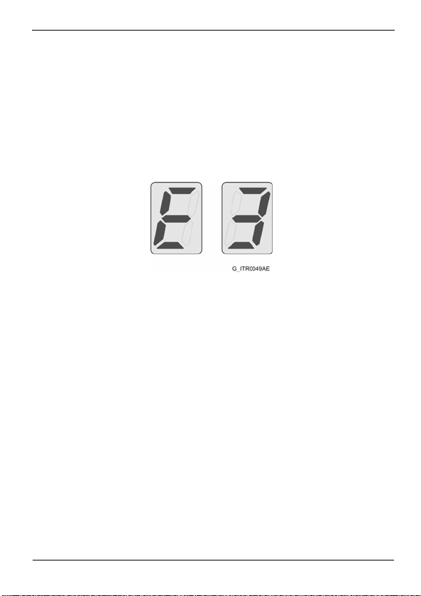
0x01 to 0x7D. In case of trying to assign a not valid address, for
example 0xFF, display will show Error 3.
Figure 3.12 Message of Error 3 – Error in Profibus controller
When the Profipower gateway starts at the first time, it will try to
communicate by the Modbus address that is given by the Profibus
address, that is, it will try to communicate with the address established
in the rotary selectors. This address is established as 1 by default, that
is, 0x01.
If the set address is out of the allowed range, the error above indicated
will be shown. Verify the setting of both rotary selectors and adjust
them properly.
If, after all, the gateway does not obtain any answer, a search of the
Modbus address of the connected equipment will be realized. This
process can take around 35 seconds (approximately). Once an answer
is found, it assigns the Profibus address to the equipment.
INSTALLATION AND CONNECTION
23
Page 26
PROFIPOWER POWER ELECTRONICS
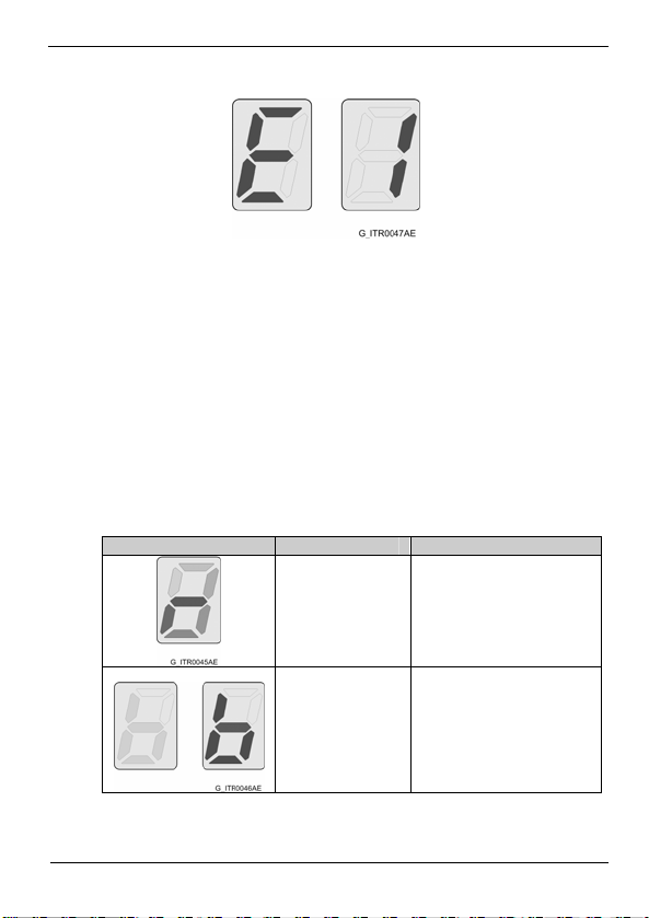
If it does not find any answer, display will show Error 1.
Figure 3.13 Message of Error 1 – Modbus communication error
The Profibus part of the gateway starts completely for the purposes of
configuration by the Profibus Master. Obviously, the sending and
reception through Modbus will not be realized until the Modbus part is
initialized.
If the Profibus address is changed, the gateway will be restarted and
the process will be repeated.
3.4. Display and Faults Code
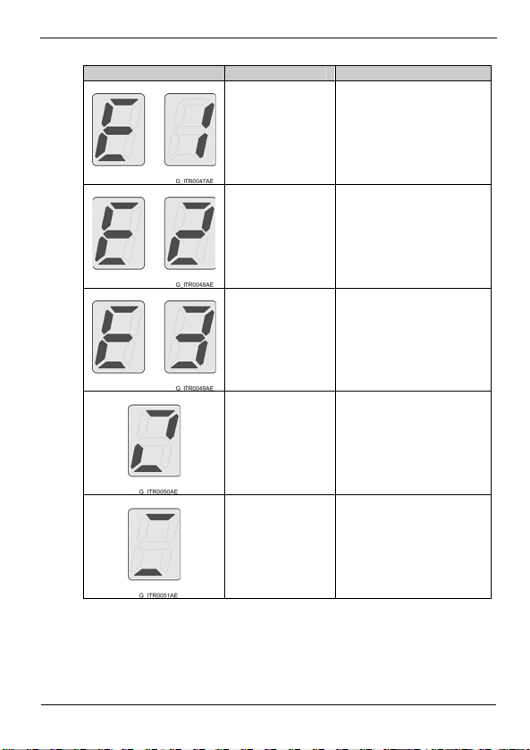
The display that indicates the status will show different messages
according to the following codification:
Display Message Description
INSTALLATION AND CONNECTION
24
Consecutive
lighting of all of the
leds
"b" blinking
Firmware reset of the
gateway.
It is searching a Modbus
device.
Page 27
POWER ELECTRONICS PROFIPOWER
Display Message Description
Error 1. It alternates
"E" with "1"
Error 2. It alternates
"E" with "2"
Error 3. It alternates
"E" with "3"
Modbus communication error.
Profibus controller is not
initialized.
Error in Profibus controller.
The gateway is not
Double blade
configured by the Profibus
master.
Two horizontal lines
The gateway is in data
exchange status.
INSTALLATION AND CONNECTION
25
Page 28

PROFIPOWER POWER ELECTRONICS
4. TRIAL RUN
4.1. Introduction
Profipower-Gateway device is a ProfiBus-DP slave with the following
characteristics:
Modular station with 6 modules.
Diagnosis with status message.
Before beginning the information exchange between the slave and the
Profibus network, the slave should be configured by the master. There
are several main services that are described below.
4.1.1. Diagnosis
Between the standard continuous cycles of communication and in
the beginning stage of the network, the master sends continuous
diagnosis messages. These messages allow the master to know if a
new slave has been configured by reading the status in the network
of the drive.
The master supplies the required parameters and configurations that
still have not been installed.
Once the slave is into the network, diagnosis data exchange is only
used by the slave to notify the master a change in the operation
status. The use of these messages is extensive to notify errors in the
gateway.
4.1.2. Set up
The set up messages are frames (up to 244 bytes of length) that
contain all of the configuration parameters of the Profipower
gateway. The gateway uses this information to configure the
Modbus communication before entering in data exchange mode.
TRIAL RUN
26
Page 29

POWER ELECTRONICS PROFIPOWER
4.1.3. Configuration
Configuration message indicates the size of the I/O transference
messages to the slave.
The modules that can be configured are the following ones:
ProfiPower Type 1
Generic module. 5 output registers, 5 input registers.
ProfiPower Type 2
Generic module. 60 output registers, 60 input registers.
ProfiPower SD700 Type 1
Specific module for Variable Speed Drive SD700.
5 output registers, 5 input registers.
ProfiPower SD700 Type 2
Specific module for Variable Speed Drive SD700.
60 output registers, 60 input registers.
ProfiPower SD700 Type 3
Pre-defined module for SD700 Series.
5 output registers Output, 2 input registers.
ProfiPower SD700 Type 4
Pre-defined module for SD700 Series.
27 output registers, 23 input registers.
The gateway reports the Profibus Master the possible errors that can
be produced in it. For that, it uses the frames of diagnosis
notification that can be visualized by any Profibus Master Software.
The errors that can be notified are the following ones:
TRIAL RUN
27
Page 30

PROFIPOWER POWER ELECTRONICS
4.1.4. Errors referred to the configuration
o Err. WR REG. NUMBER
Number of writing registers is not valid.
o Err. RD REG. NUMBER
Number of reading registers is not valid.
o Err. PARAM. LENGTH
Parameters length is not valid.
o Err. SCEN. NUMBER
Number of scenarios is not valid.
o Err. MODBUS DEVICE
Fault in the Modbus part.
o Err. CONFIG. FRAME
Fault in the Profibus frame.
o Err1: MODBUS CRC
Error CRC.
o Err2: FN UNKNOWN
Unknown Modbus function.
o Err4: MODBUS Timeout
Communication fault. Exceeded time.
28
TRIAL RUN
Page 31

POWER ELECTRONICS PROFIPOWER
4.1.5. Errors referred to the communication
o Err11: ILLEGAL FUNCTION
Not valid function. The received function code is not allowed for the
slave. This is possible because the code is only for newer elements
and it is not implemented in the selected unit. Also it can indicate
that the master or the slave is in a wrong status for the processing of
this type of functions (for example, because the device is not
configured and registers values are being asked to it).
o Err12: ILLEGAL DATA ADDRESS
The received data address is not an address allowed for the master
or the slave. In detail, the combination of the reference number and
the transferred length is not valid. For a controller with 100 registers,
a request with an offset of 96 and length of 4 will operate correctly,
but a request with an offset of 96 and length of 5 will generate an
exception code 12.
o Err13: ILLEGAL DATA VALUE
A value contained in the data field of the request is not allowed for
the master or the slave. This indicates a fault in the remainder
structure of a complex request, therefore, the implicated length is
not correct.
o Err14: SLAVE DEVICE FAI LURE
Non-recoverable error has been produced while the master or the
slave was waiting for executing the requested action.
TRIAL RUN
29
Page 32

PROFIPOWER POWER ELECTRONICS
o Err15: ACKNOWLEDGE
Specific use together with programming orders. The master or the
slave has accepted the request and is processing it, but the device
will take a long time to do it. To avoid a fault due to exceeded time
(time-out) in the customer part, it will send this answer.
o Err16: SLAVE DEVICE BUSY
Specific use together with programming orders. The master or the
slave is processing a long duration command. The master should
transmit this request later again.
o Err18: MEMORY PARITY ERROR
Specific use together with function codes 20 and 21. The reference
type 6, to indicate that the extended part of the file, has failed when
passing the consistency test. The master or the slave tries to read a
recorded file, but a parity error in the memory is detected.
o Err20: GATEWAY PATH UNAVAILABLE
Specific use together with interfaces. It indicates that the interface
(gateway) is unable to assign an internal communication path from
the input port to the output port to process the requests.
o Err21: GATEWAY FAIL ED TO RESPOND
Specific use together with interfaces. It indicates that any answer
has not obtained from the device. It usually means that the element
is not present in the network.
4.1.6. Data Exchange
Once the Set up and Configuration telegrams have been accepted,
the gateway goes into the information exchange mode with the
profibus master.
TRIAL RUN
30
Page 33
POWER ELECTRONICS PROFIPOWER
4.2. Trial Run with Siemens (Step 7 Set-up)
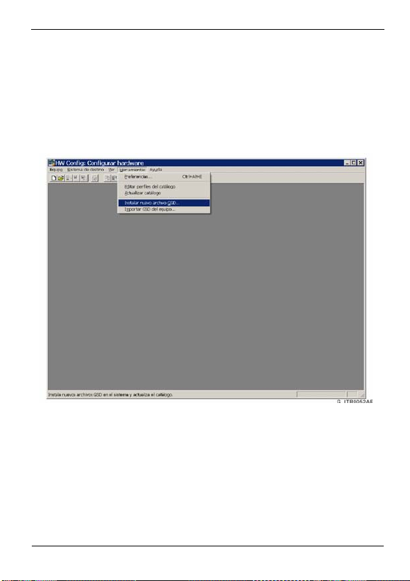
4.2.1. Installation of GSD File
Install GSD file with the hardware configuration tool of the SIMATIC
administrator.
Figure 4.1 Screen 1 of GSD file installation
TRIAL RUN
31
Page 34
PROFIPOWER POWER ELECTRONICS
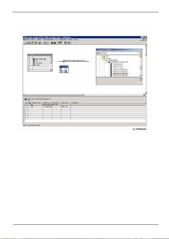
Select PWE_O5DD.GSD file.
Then, create a new project and insert a master and a slave.
Figure 4.2 Screen 2 of GSD file installation
Once inserted the slave, a module should be assigned to this slave,
and should be configured correctly. For that reason, it is
fundamental to know how many registers are going to be written and
how many registers are going to be read.
All of the modules available in the Profipower gateway are described
in the following section.
32
TRIAL RUN
Page 35

POWER ELECTRONICS PROFIPOWER
4.3. Configuration and Set up.
4.3.1. Profipower Type 1 module.
It is a generic module that allows 5 output registers and 5 input
registers.
To configure this generic module, we will define the parameter
“Scenario”. The Scenarios are the Modbus frames that we want to
send.
Each Scenario is completely defined with a base address of Modbus
register and a number of Modbus registers from this base address.
This determines the Modbus registers block to be read or written.
If base address is 40000, and 5 registers can be written, the
scenario can be configures with the address 40000 and the position
5. This allows writing in the addresses from 40000 to 40004, all
consecutive. This is also valid for the reading function.
For this module it can be defined up to 10 Scenarios, such as it has
been indicated above. These Scenarios are 5 for the write command
and the other 5 are for read command. This is a generic module
and, therefore, it is independent of the equipment connected to the
gateway. For this reason, user will be responsible of the knowledge
of the valid Modbus registers for the equipment that is going to be
connected.
Thanks to this, the registers can be alternate or random instead of
consecutive. In this way, for example, if you want to write in the
registers 40000, 40008, 40012, you should configure 3 writing
scenarios: the first one with the address 40000 and the position 1,
the second one with the address 40008 and the position 1, and the
third one with the address 40012 and the position 1. So, it is being
indicating from each position it only will be written 1 register (the
indicated one).
TRIAL RUN
33
Page 36

PROFIPOWER POWER ELECTRONICS
The defined frames for this module are: 10 bytes of Data-Output and
10 bytes of Data-Input.
Therefore, the maximum number of selected Modbus registers will
be 5 for the writing Scenarios and 5 for the reading Scenarios. That
is, all the registers selected for the configured writing Scenarios do
not exceed 5. And in the same way, all the registers selected for the
configured reading Scenarios do not exceed 5.
Note: When you introduce the Modbus addresses of the desired
parameters for reading and writing in the Hardware configuration of
the gateway, you should consider the following points:
If the slave equipment is a model of SD250 or SD450
Series, the addresses will be introduced by subtracting “1”
to the value that appears in the manual of this equipment.
For example: if the address indicated in the manual is
“0x000A”, you should introduce the value “9”.
If the slave equipment is a model of SD700 Series or V5,
you should subtract “40001” to the address indicated in the
manual of the equipment, and then you should introduce the
resultant value in the gateway configuration. For example, if
the address indicated in the manual is “40003” you should
introduce the value “2”.
Is the slave equipment is a model of SD700 Series and it is
configured from a base address as much of reading as of
writing, you should make sure the registers that you want to
access have modbus addresses correlative to selected
base address. Consult the modbus communication manual
of the equipment for additional information.
The description of the Profibus frame will be determined by the
realized set up of the scenarios.
As well as the Scenarios, we will have to configure the parameter
“Modbus Device” to indicate the Modbus device that is going to be
connected to the gateway.
34
TRIAL RUN
Page 37

POWER ELECTRONICS PROFIPOWER
The gateway supports the following Modbus slaves:
Variable Speed Drive of SD700 Series.
Variable Speed Drive of SD450 Series.
Variable Speed Drive of SD250 Series.
Digital Soft-Started of V5 Series.
Note: To connect other slaves, contact with Power Electronics.
Finally, also the parameters related to the Modbus communica tion
can be configured:
Transmission Speed (Baud rate)
Exceeded Time (Time out)
Stop bit
Parity bit
Retries
4.3.2. Profipower Type 2 Module
For this module it can be defined up to 20 Scenarios, 10 for the write
command and the other 5 for the read command. It is a generic
module and, therefore, it is independent of the equipment connected
to the gateway. For this reason, user will be responsible of the
knowledge of the valid Modbus registers for the equipment that is
going to be connected.
The defined frames for this module are: 120 bytes of Data-Output
and 120 bytes of Data-Input.
TRIAL RUN
35
Page 38

PROFIPOWER POWER ELECTRONICS
Therefore, the maximum number of selected Modbus registers will
be 60 for the writing Scenarios and 60 for the reading Scenarios.
That is, all the registers selected for the configured writing Scenarios
do not exceed 60. And in the same way, all the registers selected for
the configured reading Scenarios do not exceed 60.
The configuration of the Scenarios will be realized in the same way
that has been explained for the Profipower Type 1 Module.
Note: When you introduce the Modbus addresses of the desired
parameters for reading and writing in the Hardware configuration of
the gateway, you should consider the following points:
If the slave equipment is a model of SD250 or SD450
Series, the addresses will be introduced by subtracting “1”
to the value that appears in the manual of this equipment.
For example: if the address indicated in the manual is
“0x000A”, you should introduce the value “9”.
If the slave equipment is a model of SD700 Series or V5,
you should subtract “40001” to the address indicated in the
manual of the equipment, and then you should introduce the
resultant value in the gateway configuration. For example, if
the address indicated in the manual is “40003” you should
introduce the value “2”.
Is the slave equipment is a model of SD700 Series and it is
configured from a base address as much of reading as of
writing, you should make sure the registers that you want to
access have modbus addresses correlative to selected
base address. Consult the modbus communication manual
of the equipment for additional information.
The description of the Profibus frame will be determined by the
realized set up of the scenarios.
As well as the Scenarios, we will have to configure the parameter
“Modbus Device” to indicate the Modbus device that is going to be
connected to the gateway. The gateway supports the Modbus slaves
that have been enumerated in the previous section.
36
TRIAL RUN
Page 39

POWER ELECTRONICS PROFIPOWER
And also the parameters related to the Modbus communication that
have been indicated for the generic module type 1 can be
configured.
4.3.3. Profipower SD700 Type 1 Module
For this module it can be defined up to 10 Scenarios, 5 for the write
command and the other 5 for the read command. This module is
specific for the SD700 drive, therefore, the gateway will be set up
with the valid Modbus address for the SD700. User only must select
the available Modbus registers.
The defined frames for this module are: 10 bytes of Data-Output and
10 bytes of Data-Input.
Therefore, the maximum number of selected Modbus registers will
be 5 for the writing Scenarios and 5 for the reading Scenarios. That
is, all the registers selected for the configured writing Scenarios do
not exceed 5. And in the same way, all the registers selected for the
configured reading Scenarios do not exceed 5.
The description of the Profibus frame will be determined by the
realized set up of the scenarios.
And also the parameters related to the Modbus communication that
had been indicated for the generic module type 1 can be configured.
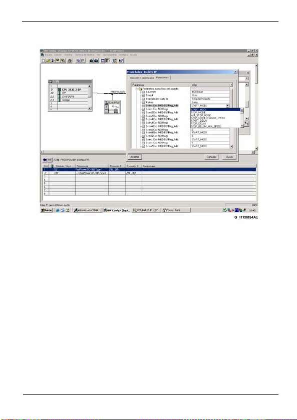
The following figure shows an example of Scenarios set up for the
Profipower SD700 Type 1 Module.
TRIAL RUN
37
Page 40
PROFIPOWER POWER ELECTRONICS
Figure 4.3 Configuration screen of Profipower SD700 type 1 Module
Once selected this module, it will not be necessary to introduce the
memory addresses, but rather it will be possible to work with the
name of the variables directly, such as the previous figure shows.
38
TRIAL RUN
Page 41

POWER ELECTRONICS PROFIPOWER
4.3.4. Profipower SD700 Type 2 Module
For this module it can be defined up to 20 Scenarios, 10 for the write
command and the other 10 for the read command. This module is
specific for the SD700 drive, and it will operate in the same way that
the module described previously. The gateway will be set up with the
valid Modbus address for the SD700. User only must to select the
available Modbus registers.
The defined frames for this module are: 120 bytes of Data-Output
and 120 bytes of Data-Input.
Therefore, the maximum number of selected Modbus registers will
be 60 for the writing Scenarios and 60 for the reading Scenarios.
That is, all the registers selected for the configured writing Scenarios
do not exceed 60. And in the same way, all the registers selected for
the configured reading Scenarios do not exceed 60.
The description of the Profibus frame will be determined by the
realized set up of the scenarios.
And also the parameters related to the Modbus communication that
had been indicated for the generic module type 1 can be configured.
TRIAL RUN
39
Page 42
PROFIPOWER POWER ELECTRONICS
4.3.5. Profipower SD700 Type 3 Module
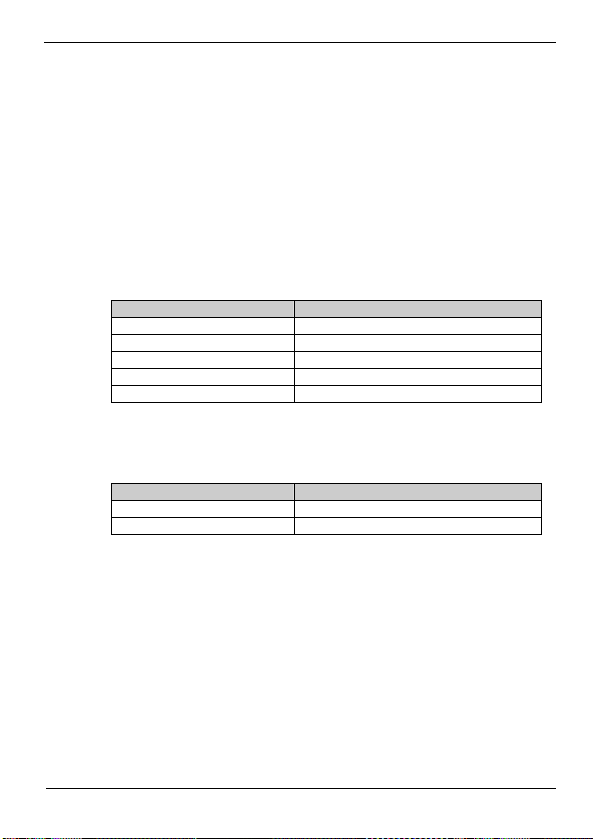
This module and the next one are modules for the SD700 that
already have the Modbus registers for reading and writing defined.
User only must write the value of the registers.
Pre-defined registers for these modules are shown in the attached
table.
The Profipower gateway receives 10 bytes of output data of the
ProfiBus-DP Mast er.
Output Data (Word) Variables
0 LOCAL_SPEED_REF
1 HOST_START_CONTROL
2 HOST_STOP_CONTROL
3 HOST_RESET_CONTROL
4 HOST_TRIP_CONTROL
The Profipower gateway sends 4 bytes of input data to the ProfiBusDP Master.
Input Data (Word) Variables
0 ACTUAL_SPEED_REFERENCE
1 GENERAL_STATUS
40
TRIAL RUN
Page 43
POWER ELECTRONICS PROFIPOWER
4.3.6. Profipower SD700 Type 4 Module
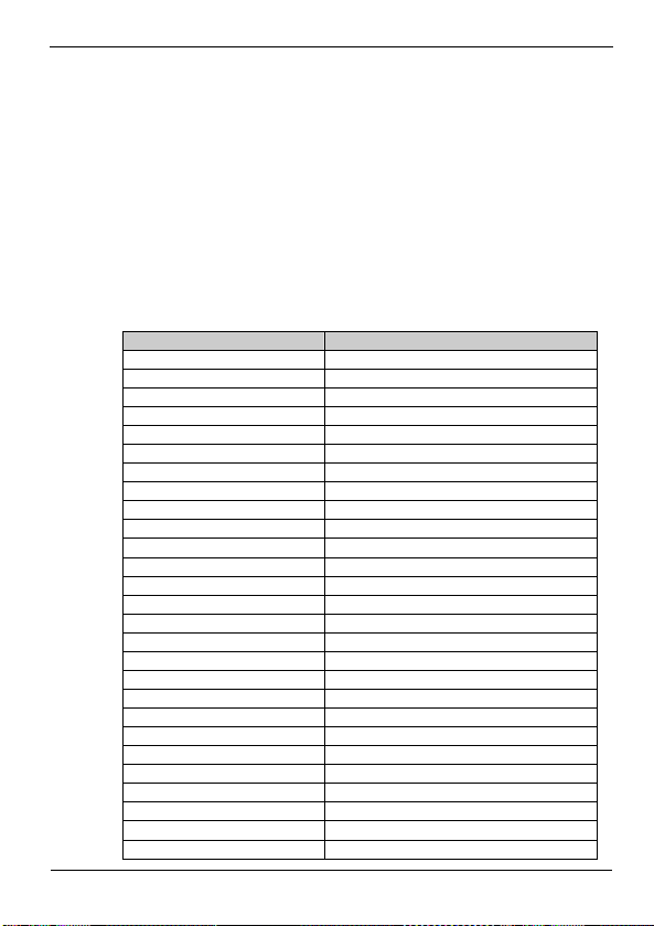
This is also a pre-defined module, although broader than the
previous one. A high number of Modbus registers for reading and
writing has been defined. User only must write the value of the
registers.
Pre-defined registers for these modules are shown in the attached
table.
The Profipower gateway receives 54 bytes of output data of the
ProfiBus-DP Mast er.
Output Data (Word) Variables
0 LOCAL_SPEED_REF
1 HOST_START_CONTROL
2 HOST_STOP_CONTROL
3 HOST_RESET_CONTROL
4 HOST_TRIP_CONTROL
5 LIMIT1_MIN_SPEED
6 LIMIT2_MIN_SPEED
7 LIMIT1_MAX_SPEED
8 LIMIT2_MAX_SPEED
9 CURRENT_LIMIT
10 TORQUE_LIMIT
11 INVERTED_SPEED_ENABLED
12 NAMEPLATE_MOTOR_CURRENT
13 NAMEPLATE_MOTOR_POWER
14 ACCELERATION_RATE
15 ALT_ACCELERATION_RATE
16 DECELERATION_RATE
17 ALT_DECELERATION_RATE
18 ACC_BRAKE_SPEED
19 DEC_BRAKE_SPEED
20 CURRENT_LIMIT_TIMEOUT
21 STOP_TIMEOUT
22 TORQUE_LIMIT_TIMEOUT
23 SUPPLY_UNDER_VOLTAGE
24 SUPPLY_OVE_VOLTAGE
25 CURRENT_LIMIT
26 TORQUE_LIMIT
TRIAL RUN
41
Page 44
PROFIPOWER POWER ELECTRONICS
The Profipower gateway sends 46 bytes of input data to the
ProfiBus-DP Mast er.
Input Data (Word) Variables
0 ACTUAL_SPEED_REFERENCE
1 GENERAL_STATUS
2 OUTPUT_MOTOR_CURRENT
3 OUTPUT_MOTOR_TORQUE
4 OUTPUT_MOTOR_POWER
5 OUTPUT_MOTOR_VOLTAGE
6 OUTPUT_MOTOR_FREQUENCY
7 MOTOR_COS_PHI
8 MOTOR_SPEED_RPM
9 MOTOR_SPEED_PERCENTAGE
10 DC_BUS_VOLTAGE
11 INPUT_VOLTAGE
12 ANALOG_INPUT_1_VALUE
13 ANALOG_INPUT_2_VALUE
14 ANALOG_OUTPUT_1_VALUE
15 ANALOG_OUTPUT_2_VALUE
16 DIGITAL_INPUT_STATUS
17 DIGITAL_OUTPUT_STATUS
18 COMPARATOR1_STATUS
19 COMPARATOR2_STATUS
20 COMPARATOR3_STATUS
21 ACTUAL_CTRL_SETPOINT
22 ACTUAL_FEEDBACK
42
TRIAL RUN
Page 45
POWER ELECTRONICS PROFIPOWER
5. PROGRAMMING FOR STEP 7
The controller of the device that is going to be connected to the gateway will
be realized by using the PDOs (Process Data Objects) defined as modules of
different length, in the gateway configuration. These PDOs can be mapped in
the data area of a PLC, in case of using this one like Master ProfiBus.
Since all of the modules (or PDOs) defined for the gateway have more than 3
or 4 bytes of length, the SFCs (special system functions) SFC14 DPRD_DAT
and SFC 15 DPWR_DAT will be used for data transmission and reception.
The following table shows the SFCs that will be used according to the
modules selected for the gateway.
ProfiPower Module Access path for Step 7
Profipower type 1 SFC14 (10 bytes)
Profipower type 2 SFC14 (32 + 32 + 32 + 24 bytes)
Profipower SD700 type 1 SFC14 (10 bytes)
Profipower SD700 type 2 SFC14 (32 + 32 + 32 + 24 bytes)
Profipower SD700 type 3 SFC14 (4 bytes)
Profipower SD700 type 4 SFC14 (32 + 14 bytes)
SFC15 (10 bytes)
SFC15 (32 + 32 + 32 + 24 bytes)
SFC15 (10 bytes)
SFC15 (32 + 32 + 32 + 24 bytes)
SFC15 (15 bytes)
SFC15 (32 + 22 bytes)
PROGRAMMING FOR STEP 7
43
Page 46

PROFIPOWER POWER ELECTRONICS
5.1. Example of program for Step 7
In the following example, the Profipower gateway is configured with the
Profipower SD700 Type 3 Module.
Two Data Blocks are created: DB1 (Data Block 1) with 5 registers and
DB2 (Data Block 2) with 2 registers.
Input data are copied to the DB2 by calling SFC14. Output data are
copied from DB1 by calling SFC15.
Verify the length in bytes for the RECORD field must be the same as
the configured module.
For additional information about the SFCs, consult the STEP 7 aid.
// Data Input
CALL "DPRD_DAT"
LADDR :=W#16#100
RET_VAL:=MW1
RECORD :=P#DB2.DBX0.0 BYTE 4
// Data Output
CALL "DPWR_DAT"
LADDR :=W#16#100
RECORD :=P#DB1.DBX0.0 BYTE 10
RET_VAL:=MW2
PROGRAMMING FOR STEP 7
44
Page 47
POWER ELECTRONICS PROFIPOWER
5.2. Monitoring and Modification of Modbus
Registers
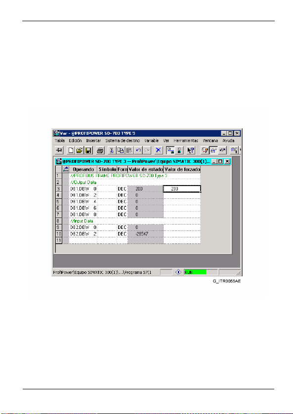
The following figure shows a value table created with Step7 for
monitoring and modifying Modbus registers. This table corresponds to
a gateway configuration with the Profipower SD700 Type 3 Module.
Figure 5.1 Monitoring and modification of Modbus registers
PROGRAMMING FOR STEP 7
45
Page 48
PROFIPOWER POWER ELECTRONICS
6. DIAGNOSIS
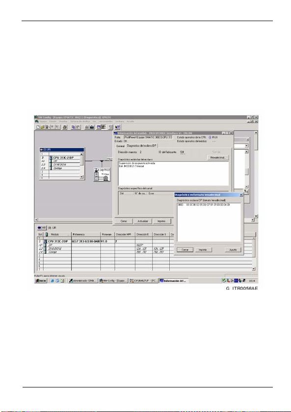
The Profipower gateway is able to send diagnosis messages.
The following figure shows an example of gateway diagnosis notification.
Concretely, it notifies a Modbus communication error due to TimeOut.
Figure 6.1 Sending of diagnosis messages
46
DIAGNOSIS
Page 49

POWER ELECTRONICS PROFIPOWER
DIAGNOSIS
47
Page 50

www.power-electronics.com
24 Hours Technical Assistance 365 days a year 902 40 20 70
HEAD OFFICE
INTERNATIONAL
BRANCHES:
GERMANY
KOREA
CHINA
AUSTRALIA
C/ Leonardo da Vinci, 24 - 26, Parque Tecnológico · 46980 · Paterna · VALENCIA
Tel. (+34) 96 136 65 57 · Fax. (+34) 96 131 82 01
Power Electronics Deutschland GmbH
Conradtystrasse, 41 · D-902441 · NÜRNBERG · GERMANY
Tel. (+49) 911 99 43 99 0 · Fax (+49) 911 99 43 99 8
Power Electronics Asia HQ Co.
Room #305, SK Hub Primo Building 953-1, Dokok-dong, Gangnam-gu · SEOUL ·
135-270 KOREA
Tel. (+82) 2 3462 4656 · Fax (+82) 2 3462 4657
Power Electronics Guangzhou
Room 3608 (IVEX) CITIC Plaza Building 233, TianHe North Road
510613 · Guangzhou · Guangdong · P.R. CHINA
Tel. (+86) 20 87 520 092 · Fax (+86) 20 38 773 559
Power Electronics Australia Pty Ltd
U6, 30-34 Octal St, Yatala, Brisbane, Queensland 4207 · P.O. Box 3166
Browns Plains · Queensland 4118 · AUSTRALIA
Tel. (+61) 7 3386 1993 · Fax. (+61) 7 3386 1997
Page 51
www.power-electronics.com
 Loading...