

Powered Aire RBT1-36 Installation Manual
POWERED AIRE
INC.
www.poweredaire.com
POWERED AIRE
TM
INC.
INSTALLATION INSTRUCTIONS
(Model RBT)
*Trained and experienced mechanic / electrician required
Visible or Concealed Damage:
Claims should be made immed ia te ly to th e transportation company. Do no t de lay filing a claim. Powered Aire will not be liable
for damage claims submitted late.
Unpacking:
Carefully remove enough of crate to expose inlet screws. Remove Phillips head screws holding intake screen in place. Remove
screen and filters (if provided ), sav e screws. Use 3/8" socket and extension to remove four lag bolts. Unit is now ready for
removal. Unit can be lifted by blower housing inlets . (Ca utio n - Be caref ul not to grasp by blo we r wh ee ls . The y will bend and
throw wheels out of balance, affecting safety and performance of air curtain.)
Electrical Installation:
Units must be field wired in accordance with all local and national electric codes, including wire size and materials.
Mounting Note:
The air curtain should be mounte d as close to the door header/opening as possible for maximum performance. For every one inch
the bottom of the aire curtain is mounted above the door header, the back side of aire curtain should be moved
away from the wall 1/2 inch. The unit is to be inst alled such that the bottom of the air curtain is no more than 7' above the finished
floor in order to comply with the NSF/ANSI 37 standard.
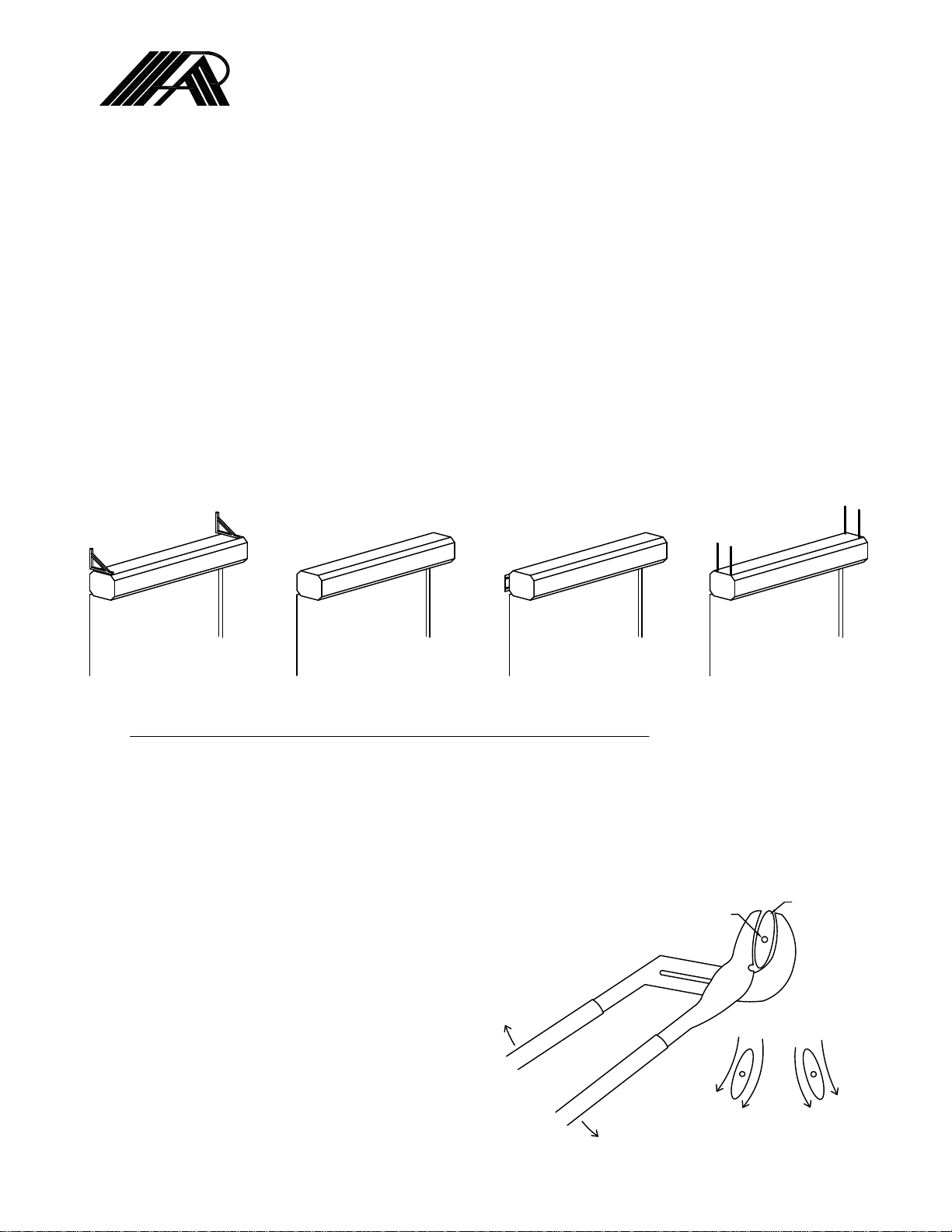
Mounting Option 1:
Top Mount - Unit has four 3/8-16 threaded inserts for installing one end of threaded rods. The other ends of the thre aded rods
can be attached to the ceiling. Threaded rod should not extend more than 3/4 inch into aire curtain.
Threaded rods, angle brackets, and struts provided by others.
For mounting over turnback doors, roll up canister doors, or other special applications consult factory.
Note: All hardware a n d brackets must b e of sufficient strength to safely support aire curtain.
Mounting Option 2:
Wall Mount - Back side of aire curtain has 4 mounting holes capable of accepting four 3/8 mounting bolts or lags, with washers
(use these holes only for mounting). Mark and pr e-drill mounting surface accurately. A long extension and rac he t will negate the
need to remove the motor/blower plate when installing. Mounting bolts or lags of sufficient size and strength should be installed
and tightened through the four 7/8 inch holes in motor/blower plate. If motor/blower plate has to be removed, the junction box
inside the unit must be removed along with any electrical switches that may be in the way. The electrical switc hes have a lever
that slides in one direction t o release the switch contacts f rom the switch body. All wires will then stay intact for easy installation
when replacing blower plate. Remove 7/16 whizlock nuts holding plate in place, and slide plate out, rotating top portion of plate
so it comes out first. Rememb er when install i ng plate to put bottom of plate in first and rotate top in last.
VANE PIVOT POINT
VANE
Air Directional Adjustment:
Air curtain comes equipped with a steering vane in the
discharge to allow for the outward adjustment of the
discharge air direction. To adjust, fir st wrap a rag
around the vane so it is not scratched. Grip the vane
near the end on one side with a pair of channel locks
and rotate it in the direction that you want the air to
flow. Repeat for the other side.
Periodic cleaning of the steering vane may be required.
W
O
L
F
R
I
A
A
I
R
F
L
O
W
To clean it just wipe it down with a damp rag.
109 Mortensen Rd. Greenville, PA 16125 Phone: 888-321-AIRE or 724-588-3305 Fax: 724-588-3371
October, 2013
 Loading...