

Page 1
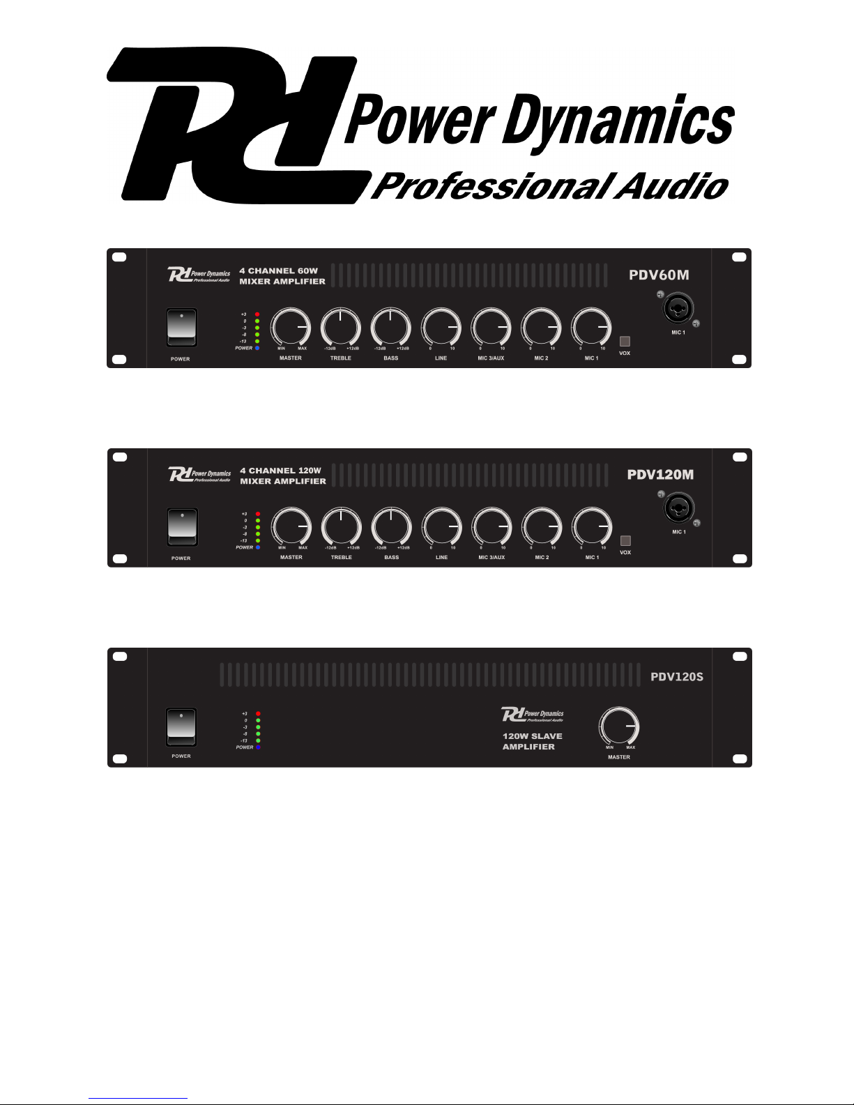
PDV60M 60W/100V 4 Ch. Mixer Amp.
Ref. nr. 952.050
PDV120M 120W/100V 4 Ch. Mixer Amp.
Ref. nr. 952.053
PDV120S 120W/100V Slave Amplifier
Ref. nr. 952.056
Instruction Manual
Gebruiksaanwijzing
Gebrauchsanleitung
Mode d’ Emploi
Manual de Instrucciones
Page 2
SPECIFICATIONS OF AMPLIFIERS
PDV60M PDV120M PDV120S
Output RMS 60W 120W 120W
Output 10% THD 70W 160W 160W
Output regulation < 2dB, no load to full load < 2dB, no load to full load < 2dB, no load to full load
Speaker imp. output 8 Ohm 8 Ohm 8 Ohm
Speaker imp. output 100V 166 Ohm 83 Ohm 83 Ohm
Line output (stereo) 1V @ 600 Ohm (0dB) 1V @ 600 Ohm (0dB) 1V @ 600 Ohm (0dB)
Slave output (mono) 1V @ 600 Ohm (0dB) 1V @ 600 Ohm (0dB) 1V @ 600 Ohm (0dB)
Input sensitivity Mic 1+2 1.5mV balanced 1.5mV balanced -Input sensitivity Mic 3 1.5mV unbalanced 1.5mV unbalanced -Input sensitivity Aux/Line 300mV unbalanced 300mV unbalanced 300mV unbalanced
Input impedance Mic 5 kOhm 5 kOhm -Input impedance Aux/Line 10 kOhm 10 kOhm 10 kOhm
Input Connectors Mic 1+2 XLR XLR -Input Connectors Mic 3 6.35mm Jack 6.35mm Jack -Input Connectors Aux/Line RCA socket RCA socket RCA socket
Frequency Response 100Hz - 12kHz ±3dB
Distortion THD+N < 2% @ 1KHz, on rated power
SNR (signal noise ratio) >92dB (Mic >70dB, Line 75dB)
Tone control Bass: +0dB, -10dB @ 100Hz Treble: +0dB, -10dB @ 10kHz
Protection circuits
Muting function
Power Voltage 220-240Vac / 50Hz
Power Consumption 200W 300W 300W
Dimension 19” x 2HE (425 x 88mm)
Weight 7.5kg 10kg 10kg
Ref. Nr. Tronios 952.050 952.053 952.056
Mixer Amplifier:
Slave Amplifier:
Page 3

ERIES 900 952.966 952.969 952.972 952.975
INTRODUCTION
The POWER DYNAMICS PDV series of amplifiers are designed for industrial use in factories, offices and
public buildings. Three microphone inputs are provided. In addition a LINE input is also available which can be
used for music sources and similar higher signal sources. There is also an output suitable for feeding the
POWER DYNAMICS slave amplifier in the same series thus making amplifier stacking a possibility. Provision is
made for connecting to either 100 volts to line or low impedance loudspeakers. The amplifier can be used from
either a 220-volt AC or a DC power source. Within the packaging will be found a 3 core 230V mains lead
terminated with a IEC connector at one end.
WARNING: DO NOT CONNECT THE MAINS SUPPLY TO THE AMPLIFIER UNTIL ALL THE
NECESSARYINPUT AND OUTPUT CONNECTIONS HAVE BEEN MADE.
NOTE: If you are connecting the amplifier to two-wire power source i.e. have no earth pin available then
essential that a suitable wire is run from the chassis binding post adjacent to the mains lead on the rear to a
proven earth.
PANEL DISCRIPTION
FRONT PANEL viewed from right to left. See the front page for a diagram. Three controlled channels are
provided. MIC 1 and MIC 2 are on the right with the LINE, BASS and TREBLE cut controls towards the left
hand side. The MASTER control is next with the signal monitoring and the mains on/off switch at the extreme
right.
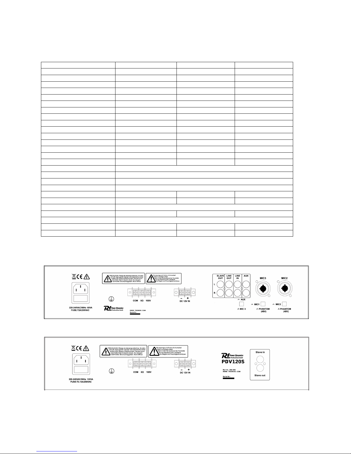
REAR PANEL viewed from left to right. See the front page for a diagram. On the left is found the IEC input
incorporating a mains fuse. Next is the chassis binding post with the DC input terminals adjacent to the
loudspeaker termination. Towards the right there is the SLAVE OUT RCA socket which can be used for
recording purposes. Next are the LINE OUT and LINE IN sockets followed by the socket for MIC. See the
specification panel for full technical details.
PROTECTION
The amplifier is automatically protected for short, open circuit and overheating. A short or open circuit on the
loudspeaker line is indicated by the POWER indicator pulsing slowly on and off. Overheating in excess of
105°C is protected by a thermal cut out and if this occurs then the amplifier will cut out completely. The cause
is usually by the placing of papers on top of the amplifier or by enclosing it in a poorly ventilated place. If this
happens remove any restrictions on ventilation and leave the amplifier switched off for five minutes. This will
restore the protection circuits to their monitoring mode. If the fault had existed for some time then the fuse
located adjacent to the IEC connector on the rear panel may also need replacement. In this case the POWER
indication on the front panel will fail to illuminate.
INSTALLATION
MIC is for a balanced microphone on an XLR3 socket: twin screened wire should be used for connection.
Termination follows the convention i.e. pin 1 – Screening; pin 2 - Signal go; pin 3 – Signal return. MIC 1 has
the added facility of being able to duck all other inputs on the presence of a signal. No additional wiring is
required and the switch to activate this facility (VOX) will be found at the front. Compact disc and tape players
will use the LINE IN phono (RCA) socket and need to be terminated with a phono (RCA) plug, the live (inner)
wire going to the central pin with the outer screening being soldered to the body. If a recording facility is
required then suitable feed can be found by using the SLAVE OUT socket at the rear. Connect as for players
(see above) This socket can also be used for distributing a signal to up to ten POWER DYNAMICS slave
amplifiers. Caution Care must be taken when fitting any connectors to avoid damaging the cable or the
connector through excessive heat from the soldering tool.
LOUDSPEAKERS
All connections to the loudspeaker terminals should be made suing suitable spade lugs crimped or soldered to
the loudspeaker cables. Any other method can give rise to short circuit. There is provision for both 100 volts
line and low impedance loudspeakers but it is not advisable to use both together. Low Impedance
loudspeakers should he connected in a series parallel arrangement such that the total load is never less than 8
ohm. i.e. two 4 ohm loudspeakers could be connected in series and connected between the common and the 8
Page 4

ohm tap. Care should be taken with this arrangement that the volume level is carefully controlled, as it is
possible to damage loudspeakers by using too high a volume setting. The 100 volt line loudspeakers should be
connected to the common and the 100 volt line terminals taking care that the sum of the wattage of all the
loudspeakers on he line does not exceed the total power available from the amplifier. Please Note that all the
loudspeaker terminals are fully floating with respect to chassis. In the event of cross talk to other services or
instability then it may be beneficial if the ‘com’ terminal is strapped to the earth binding post. Please remember
that a low impedance loudspeaker system requires heavy cable feeding the loudspeakers to minimize losses.
For a widespread installation (i.e. a factory system) it is far better and more cost effective to use the 100 volt
line system.
MOUNTING BRACKETS.
These will be found in the packaging with the mains lead. The mounting holes can be used in one of two ways:
1. As ears for use when mounting the amplifier into an equipment rack.
2. To mount the amplifier on top of a shelf.
BATTERY OPERATION
A battery can be connected using suitable spade lugs crimped and soldered to the battery cables. Care must
be taken to ensure that the terminals lie in the spaces provided and do not swing to one side and thus short out
on the mounting screws. Polarity should be observed when connecting to the amplifier although there is
reverse polarity protection. The power output will be reduced on battery working, the output also depending on
the state of the battery. Please note that the power switch does not control the DC supply to the amplifier. If
battery On/Off control is required then a separate switch will need to be installed remote to the amplifier.
SETTING UP
When all connections have been made, check that all controls are at zero then plug the mains lead provided
into the amplifier and the plug top into a suitable 230 volt socket. Depress the double pole power switch on the
left-hand side of the front panel. Observe that the POWER LED illuminates. Advance the MASTER control to 6
on its scale then using a local microphone in MIC 1 socket slowly advance its volume control whilst speaking
into the microphone. Observe the SIGNAL indicator on the right hand side whilst doing so. As the control is
advanced the indicator will start flashing in time with the peaks of speech. This indicates that a signal is being
passed to the loudspeakers. The control should be set such that the peaks of sound keep the SIGNAL indicator
almost continuously lit but that the PEAK indicator only shows on rare occasions or not at all. Continuous
illumination of the PEAK led indicates that the amplifier is being overloaded. If the MIC control is at maximum
without achieving the desired output then it will be necessary to increase the MASTER setting a little and
recommence the setting up procedure until a satisfactory level of output is achieved. It may be that, before this
setting can be achieved, a howl-round point is reached where the system appears to become unstable, if this is
so then the nearest loudspeaker and the microphone you are using are in each others’ sound fields and need
to be repositioned the one with the other. If the 100 volt line system is being employed you can reset the nearer
loudspeaker to a lower wattage tap to minimize the howl-round. The object of this setting-up exercise is to
balance the MASTER and MIC 1 controls such that neither is at a very low or a very high setting in relation to
each other. When this initial setting-tip procedure has been completed try the other input channels in a similar
manner. Make a note of the control settings for future reference. Most tape and CD players have additional
level controls of their which can be usefully employed to fine balance their volume levels with the LINE or the
AUX control. The bass and treble cut controls should initially be set to their minimum (anticlockwise) positions
for setting up. Once this has been carried out then these can be set for personal taste. However when speech
is being transmitted into a noisy or reverberant environment then intelligence can he significantly improved by
rotating the bass cut control fully clockwise. When horn type loudspeakers are in use then the control must be
set fully clockwise to minimize the risk of low frequency damage to the loudspeakers.
INTERFERENCE
Whilst this equipment complies in all respects with EMC legislation its use in an industrial environment where
there are many potential sources of interference means that steps may need to be taken to minimize any
difficulties. Always check that the amplifier has a good earth. In the event of interference secure the services of
a qualified electrician to carry out tests on the socket in use to ensure that a low resistance earth path exists.
Do not position the amplifier very close to large transformers. television monitors and computers
Page 5

INTRODUCTIE
De POWER DYNAMICS PDV versterkers zijn ontworpen voor gebruik in fabrieken, kantoren en openbare
ruimten. De versterkers zijn voorzien van drie microfoon ingangen, en een lijningang welke gebruikt kan
worden voor het weergeven van een audiobron of vergelijkbaar signaal. De versterkers zijn voorzien van een
extra uitgang voor het aansluiten van de POWER DYNAMICS SLAVE versterker, hiermee heeft u ongelimiteerde uitbreidingsmogelijkheden. De versterkers zijn geschikt voor het aansluiten van 100 V of 8 Ohm
luidsprekers, tevens kunnen ze aangesloten worden op een 220V AC of DC voedingsspanning.
Opmerking: Het is van groot belang dat, indien de voedingsbron niet voorziet in een aardaansluiting, de
versterker met een daarvoor geschikte kabel met aarde wordt verbonden.
BEDIENING/AANSLUITINGEN
Voorzijde: Van links naar rechts, potmeters voor de microfoonkanalen, lijnsignaal, BASS en TREBLE
instellingen, de MASTER volumeregeling met uitlezing van het signaalvolume en de netschakelaar.
Achterzijde: Van links naar rechts, de aansluiting voor de 220V AC voedingsspanning, aansluiting voor de DC
voedingspanning. Aansluiting voor de luidsprekeruitgangen en de SLAVE OUT voor opname- of koppelfunctie.
LINE IN en LINE OUT met daarnaast de ingangen voor de microfoons. Voor specificaties zie het datablad.
BEVEILIGING
Opmerking: De versterkers zijn beveiligd tegen kortsluiting, onderbelasting en oververhitting. Indien de
versterker in de protect-stand staat, gelieve alle aansluitingen te controleren om eventuele storingen te
elimineren, na ongeveer 5 minuten herstelt de versterker zich (alle beveiligingscircuits zijn weer beschikbaar).
Indien een storing vaker voorkomt kan het noodzakelijk zijn de netzekering te vervangen ( indien deze defect is
zal de aan/uit- schakelaar niet oplichten).
INSTALLATIE
MIC: ingang voor het aansluiten van een gebalanceerde microfoon. Aansluitingen: Pen 1 aarde, Pen 2 +, Pen
3 -. MIC 1 is standaard voorzien van een prioriteitsfunctie, waarbij de overige signalen onderdrukt worden.
Cd-spelers en cassettedecks kunnen op de RCA-connector van de LINE-IN worden aangesloten, Indien u het
uitgangssignaal wilt opnemen of doorkoppelen dient u de LINE-OUT te gebruiken.
Opmerking: Om beschadiging van uw versterker te voorkomen dient u die juiste connectoren te gebruiken.
LUIDSPREKERS
De aansluitingen van de luidsprekers dient te gebeuren met vork- of ringterminals welke aan de draad gesoldeerd of gekrompen is. Elke andere montagemethode kan kortsluiting of niet functioneren als gevolg
hebben. Het is niet toegestaan 100V en laagohmige luidsprekers tegelijk aan te sluiten. Laagohmige luidsprekers moeten op een dusdanige wijze worden aangesloten dat de belasting nooit hoger wordt dan 8 Ohm.
Twee 4 Ohm luidsprekers dienen dus in serie te worden aangesloten op de versterkeruitgang. Het is belangrijk
om bij een laagohmige configuratie er op toe te zien dat luidsprekers nooit overbelast worden, dit om onherstelbare schade aan de installatie te voorkomen. De 100V luidsprekers moeten aangesloten worden op de
common en 100V connectoren, het totale vermogen van de luidsprekers mag nooit groter zijn dan het
maximale vermogen van de versterker. Alle luidsprekeruitgangen zijn zwevend, het kan raadzaam zijn (bijv. bij
instabiliteit) de common uitgang van de luidsprekers te verbinden met de aardaansluiting van de versterker.
Opmerking: De versterkers bij voorkeur gebruiken met 100V luidsprekers.
AANSLUITING OP EEN ACCU
Een Accu dient aangesloten te worden d.m.v. vork- of ringterminals welke aan de draad gesoldeerd of gekrompen is. Elke andere montagemethode kan kortsluiting of niet functioneren tot gevolg hebben. U dient er
voor zorg te dragen dat de spanning op de juiste wijze wordt aangesloten. Het afgegeven vermogen op de
luidsprekeruitgangen is afhankelijk van de capaciteit van de aangesloten voedingsbron. Opmerking: De aan /
uit schalekaar is specifiek bedoeld voor de 220 Volt voedingsspanning. Indien u de versterker, welke aangesloten is op een accu, wilt schakelen dient u hiervoor een extra schakelaar te monteren.
Page 6

INGEBRUIKNAME
Als de configuratie zoals die u wenst is gerealiseerd dient u ervoor te zorgen dat de spanning is uitgeschakeld
en alle volumepotmeters in de minimale stand staan. Indien u nu de voedings-spanning aansluit en de
versterker aanschakelt dient het lampje in de schakelaar op te lichten. Stel het MASTERVOLUME in op 6 en
vervolgens draait u het volume van de MIC1 omhoog terwijl u tegelijkertijd een signaal aanbiedt op deze
ingang, de weergave van het signaal-volume zal oplichten. Bij voorkeur dient het volume dusdanig ingesteld te
worden dat het PEAK-signaal minimaal oplicht of net niet, u benut in dit geval het maximale vermogen van de
versterker. Indien het PEAK-signaal continue oplicht wordt de versterker overstuurd en zal het signaal
vervormd worden weergegeven. Het kan voorkomen dat het MIC1 signaal maximaal is ingesteld en het
uitgangs-signaalvolume het maximum nog niet heeft bereikt, in dit geval kan het noodzakelijk zijn het
MASTERVOLUME te verhogen totdat het gewenste resultaat is behaald. Vervolgens stelt u de overige
signalen in op het door u gewenste niveau, dit ten opzichte van het MIC1-signaal om er voor zorg te dragen dat
u het MASTER-signaal kunt variëren met behoud van u originele configuratie. De meeste lijnuitgangen van
aangesloten apparatuur zijn instelbaar, het kan wenselijk zijn deze te variëren om een juiste balans op de
versterker te realiseren. Met de BASS en TREBLE potmeters kunt u het uitgangssignaal aanpassen aan uw
persoonlijke wensen. Bij gebruik van hoornluidsprekers is het aan te raden een minimum aan laag aan te
bieden, daar deze luidsprekers erg gevoelig zijn voor teveel laag.
INTERFERENTIE
Alle POWER DYNAMICS apparatuur voldoen aan de daarvoor geldende EMC-eisen. Indien er echter in de
directe omgeving van de versterker, leidingen of luidsprekers ernstige storingsbronnen voorkomen kan het
noodzakelijk zijn maatregelen te nemen. Het is essentieel dat de versterker met aarde wordt verbonden, dit om
te voorkomen dat er stoorsignalen kunnen ontstaan. De versterker bij voorkeur niet in de buurt van
transformators, televisies en computers plaatsen.
OPERATION MANUAL - POWER DYNAMICS 900 SERIES
Page 7

INTRODUCTION
La gamme d'amplificateurs POWER DYNAMICS a été conçue pour une utilisation industrielle dans des usines,
ainsi que dans des immeubles de bureaux et des bâtiments publics. En plus trois entrées de microphone, les
amplificateurs sont pourvus d'une entrée LIGNE qui peut être utilisée pour des sources musicales et autres
sources similaires de haut niveau. Une sortie est prévue pour alimenter un amplificateur esclave POWER
DYNAMICS, permettant la connexion en cascade des appareils. Il est possible de brancher des haut-parleurs
en technique de ligne 100V ou bien de basse impédance. L'amplificateur peut être alimenté en 220Vac ou en
DC. Le contenu du carton comprend un cordon secteur 230Vac à 3 conducteurs muni d'une fiche IEC d'un
côté et d'une fiche 13A avec fusible 5A de l'autre.
NOTE: Si vous branchez l'amplificateur sur une prise non-reliée à la terre, il est primordial que vous passiez un
fil de la borne de masse à côté du cordon secteur au dos de l'appareil à un point de masse/terre.
FACADE (vue de gauche à droite). Voir schéma sur la première page. L'amplificateur dispose de trois
canaux: MIC1 et MIC2 se trouvent sur l'extrême gauche ensemble avec les contrôles de ligne (LINE), graves
(BASS) et aigus (TREBLE). Lecontrôle général (MASTER) avec le monitor signal ainsi que l'interrupteur
général M/A se trouvent à l'extrême droite.
PANNEAU ARRIERE (vue de gauche à droite). Voir schéma sur la première page L'entrée IEC protégée par
un fusible secteur se trouve à gauche à côté du point de masse avec les fiches d'entrée 24Vdc et les fiches de
haut-parleurs. La fiche RCA SLAVE OUT peut être utilisée pour des enregistrements. Les fiches adjacentes
LINE OUT et LINE IN sont suivies par la fiche jack mono "-" pour le micro 2 avec le commutateur M/A pour la
fonction VOX. La fiche XLR pour le micro 1 se trouve complètement à droite. Vous trouverez tous les détails
techniques dans le tableau des caractéristiques.
PROTÉGÉ
L'amplificateur est automatiquement protégé contre les courts-circuits, les circuits ouverts et la surchauffe. Si la
protection se déclenche, éteignez l'amplificateur et vérifiez l'installation. Attendez 5 minutes avant une nouvelle
mise sous tension de l'amplificateur afin de remettre les circuits de protection en mode normal. Si le défaut
persiste depuis un certain temps, il peut être nécessaire de changer le fusible au dos
de l'appareil à côté de la prise IEC. Dans ce cas, l'indicateur POWER en façade ne s'allumera pas.
INSTALLATION
L'entrée MIC1 est prévue pour un microphone symétrique sur la fiche XLR3. Il est recommandé d'utiliser un
câble à double blindage. Les raccordements sont: Broche 1 = blindage, Broche 2 = envoi du signal, Broche 3 =
retour du signal. Par ailleurs l'entrée MIC1 atténue toutes les autres entrées en présence d'un signal. Cette
fonction ne nécessite pas de câblage supplémentaire. Le commutateur VOX qui permet d'activer cette fonction
se trouve au dos de l'appareil. Les entrées MIC2 et MIC3 sont des fiches jack destinées aux microphones
asymétriques de basse impédance. Il est recommandé d'utiliser un câble à blindage simple. Le conducteur
intérieur est à brancher sur la pointe et le blindage extérieur sur le corps de la fiche jack mono. S'il est
nécessaire de brancher un microphone symétrique sur l'une des entrées asymétriques, l'un des deux
conducteurs blindés intérieurs doit être connecté à la pointe et l'autre au corps de la fiche ensemble avec le
blindage extérieur. Des lecteurs de CD et de cassettes se branchent sur la fiche RCA LINE IN. Le fil positif
intérieur se connecte à la broche centrale et le blindage extérieur doit être soudé au corps. La fiche SLAVE
OUT au dos de l'appareil peut être utilisée pour raccorder un enregistreur qui se branche exactement de la
même façon qu'un lecteur (voir cidessus). Cette fiche peut également servir à l'envoi d'un signal à dix
amplificateurs esclaves POWER DYNAMICS au maximum.
Attention: Soyez particulièrement vigilent lors du branchement d'une fiche parce que la
chaleur du fer à souder risque d'endommager le câble ou la fiche.
Haut-parleurs
Toutes les connexions aux bornes de haut-parleurs se font par des cosses appropriées qui sont serties ou
soudées aux câbles des haut-parleurs. Tout autre méthode de connexion présente un risque de court-circuit. Il
y a des bornes pour des haut-parleurs à ligne 100V et des haut-parleurs de basse impédance. Il est cependant
déconseillé d'utiliser les deux en même temps. Des haut-parleurs basse impédance doivent être connectés
dans une configuration série / parallèle de façon à ce que la charge totale ne descende jamais en dessous de
Page 8

8 Ohms. Cela veut dire que deux haut-parleurs de 4 Ohms peuvent être connectés en série et branchés entre
le commun et le niveau de puissance 8 ohms. Dans cette configuration il faut contrôler de près le niveau du
volume puisqu'un volume trop élevé risque d'endommager les haut-parleurs.
Il faut connecter les haut-parleurs de ligne 100V à la borne commune et à la fiche de ligne 100V en veillant à
ce que la somme de la puissance de tous les haut-parleurs ne dépasse pas la puissance totale admissible de
l'amplificateur. Notez que toutes les bornes de haut-parleurs sont entièrement isolées de la masse. En
cas de parasites ou d'instabilité, il peut être nécessaire de relier la borne "COM" au point de terre.
Il faut garder à l'esprit qu'un système de haut-parleurs basse impédance exige un câblage très performant afin
de minimiser les pertes. Dans une installation étendue (p.ex. dans une usine), il est de loin préférable et plus
économique d'utiliser un système à ligne 100V.
ALIMENTATION PAR BATTERIE
Connectez une batterie au moyen de cosses qui seront soudées ou serties sur les câbles de batterie. Veillez à
insérer exactement les fils dans les espaces prévus sans laisser de jeu afin de ne pas créer un court-circuit
avec les vis de montage. Respectez la bonne polarité lors de la connexion bien qu'il existe une protection
contre l'inversion de polarité. La puissance de sortie est réduite lors d'une alimentation par batterie. La
puissance de sortie dépend également de l'état général de la batterie. Il faut noter que l'interrupteur général ne
commande pas l'alimentation DC vers l'amplificateur. Si vous souhaitez intégrer un interrupteur M/A pour
l'alimentation par batterie, il faut l'installer séparément de l'amplificateur.
MISE EN ROUTE
Lorsque toutes les connexions ont été effectuées, vérifiez que tous les contrôles sont réglés sur zéro et
branchez la fiche sur une prise secteur 230Vac. Appuyez sur le commutateur M/A sur la droite de la façade. Le
voyant POWER doit s'allumer. Avancez le contrôle MASTER jusqu'à 6 sur la graduation. Branchez un micro
sur la fiche MIC 1 et augmentez lentement son contrôle de volume tout en parlant dans le microphone.
Observez l'indicateur SIGNAL. Au fur et à mesure que le réglage augmente, l'indicateur clignote lors des
pointes phoniques. Ceci indique qu'un signal est envoyé aux hautparleurs. Le contrôle doit être réglé de façon
à ce que l'indicateur SIGNAL reste pratiquement allumé en permanence tandis que l'indicateur PEAK ne
s'allume que très rarement ou pas du tout. Si le voyant PEAK reste allumé constamment, cela indique une
surcharge de l'amplificateur. Si le contrôle MIC 1 est réglé au maximum sans atteindre la puissance de sortie
désirée, il faudra légèrement augmenter le réglage MASTER et recommencer la procédure de réglage jusqu'à
l'obtention d'une puissance de sortie satisfaisante. Pendant le réglage un effet larsen peut se produire et le
système devient instable. Dans ce cas, l'enceinte et le microphone les plus proches que vous utilisez, se
trouvent dans leurs champs sonores mutuels et doivent être éloignés l'un de l'autre. Si vous utilisez un
système à ligne 100V, vous pouvez régler l'enceinte la plus proche sur un niveau de puissance plus bas afin
de minimiser l'effet larsen. Le but de ce réglage est d'équilibrer les contrôles MASTER et MIC 1 de façon à ce
que ni l'un, ni l'autre ne soient réglés à un niveau trop élevé par rapport à l'autre. A l'issue de cette procédure
de réglage, testez les autres canaux d'entrée d'une manière similaire. Notez la position des contrôles pour
référence ultérieure. La plupart des lecteurs de cassettes et de CD possèdent leurs propres contrôles de
niveau qui peuvent servir à un réglage fin de leurs volumes au moyen des contrôles LINE ou AUX. Les
contrôles de tonalité des graves et aigus doivent être baissés au minimum pendant le réglage initial. Ensuite
vous pouvez les régler à votre goût. Cependant, lorsque le discours est transmis dans un environnement
bruyant et réverbérant, l'audibilité est largement améliorée si le contrôle Bass Cut est complètement tourné
vers la droite. Si vous utilisez des haut-parleurs à pavillon, le contrôle doit être réglé complètement vers
la droite pour minimiser le risque d'endommager les haut-parleurs par les basses fréquences.
INTERFERENCES
Cet appareil est en tous points conforme à la législation CEM en vigueur. Son utilisation dans un
environnement industriel en présence de nombreuses sources potentielles d'interférence peut nécessiter des
mesures pour minimiser les problèmes. Vérifiez systématiquement la connexion à la terre. En cas
d'interférences, faites appel à un électricien qualifié pour effectuer des tests sur la fiche afin de s'assurer qu'il
existe un chemin de masse de faible résistance. Ne pas placer l'amplificateur à proximité d'un grand
transformateur, d'un écran de télévision ou d'un ordinateur.
OPERATION MANUAL - POWER DYNAMICS 900 SERIES
Page 9

EINLEITUNG
Die Verstärkerserie PDV von POWER DYNAMICS ist zum industriellen Einsatz in Fabriken, Bürohäusern und
öffentlichen Gebäuden ausgelegt. Es sind drei Mikrofoneingänge vorhanden. Der LINE Eingang kann für
Musikquellen und ähnliche hochohmige Signalquellen benutzt werden. Ein Ausgang ist zum Anschluss des
Nebenverstärkers POWER DYNAMICS derselben Serie vorgesehen, so dass mehrere Verstärker
intereinander geschlossen werden können. Der Verstärker kann sowohl Lautsprecher in 100V Technik, als
auch niederohmige Lautsprecher fahren. Die Stromversorgung erfolgt über 220Vac Netzstrom oder eine
Batterie. Im Lieferumfang befindet sich ein Netzkabel mit IEC Verbinder.
HINWEIS: Wenn der Verstärker an eine Netzsteckdose ohne Erdleiter angeschlossen
wird, muss unbedingt ein geeigneter Draht von der Erdschraube am Gerät neben der
Netzbuchse an die Erde angeschlossen werden.
ANSLUSSE
VORDERSEITE (von rechts nach links). Abbildung auf der ersten Seite. Die drei Kanäle MIC1, MIC 2 und
LINE befinden sich auf der linken Seite, gefolgt von den BASS und TREBLE CUT Reglern. Der MASTER
Regler mit dem Signalmonitor und dem Ein/Aus Netzschalter befinden sich auf der rechten Hälfte.
RÜCKSEITE (von links nach rechts). Abbildung auf der ersten Seite. Ganz links befindet sich die IEC Buchse
mit der Netzsicherung. Daneben liegen die Erdschraube, die DC Eingangsverbinder und die LS-Anschlüsse.
Weiter rechts ist die SLAVE OUT Buchse, die auch für Aufnahmen benutzt werden kann. Daneben befinden
sich die LINE OUT und LINE IN Buchsen. Ganz rechts befindet sich die XLR Buchse fur MIC. Die vollständigen
technischen Daten finden Sie in der Spezifikationstabelle.
SCHUTZVORRICHTUNG
HINWEIS: Der Verstärker besitzt eine automatische Schutzvorrichtung für Kurzschluss, offene Schaltung und
Überhitzung. Wenn das Gerät in Schutzmode schaltet, schalten Sie den Verstärker aus und überprüfen Sie die
Anlage auf Defekte. Lassen Sie den Verstärker 5 Minuten ausgeschaltet, damit die Schutzvorrichtungen wieder
auf normalen Betrieb zurückschalten. Wenn der Defekt über einen längeren Zeitraum bestanden hat, kann es
notwendig sein, auch die Sicherung neben der IEC Buchse auf der Rückseite zu wechseln. In diesem Fall
leuchtet die Betriebsanzeige auf der Vorderseite nicht.
EINBAU
MIC1 ist eine XLR Buchse für ein symmetrisches Mikrofon. Für den Anschluss sollte doppelt abgeschirmter
Draht benutzt werden. Die Anschlüsse sind wie folgt: Stift 1 = Abschirmung, Stift 2 = Sendung des Signals, Stift
3 = Rückkehr des Signals. MIC1 hat die zusätzliche Funktion, alle anderen Eingänge zu dämpfen, wenn ein
Signal anliegt. Diese Funktion erfordert keine besonderen Anschlüsse. Der Schalter, der diese Funktion
aktiviert (VOX), befindet sich auf der Rückseite des Geräts. Zu ihrem Anschluss sollte einfach abgeschirmter
Draht verwendet werden, wobei der innere Leiter an die Spitze und die äussere Abschirmung an das Gehäuse
abgeschlossen werden muss. Falls ein symmetrisches Mikrofon an einen dieser asymmetrischen Ausgänge
angeschlossen werden soll, muss einer der inneren abgeschirmten Leiter an die Spitze des Klinkensteckers
und das andere zusammen mit der äusseren Abschirmung an das Gehäuse angeschlossen werden.
CD Spieler und Kassettenrekorder werden an die LINE IN Cinch Buchse angeschlossen. Dabei muss der
innere Stromleiter an den mittleren Stift und die äussere Abschirmung an das Gehäuse angeschlossen
werden. Falls Aufzeichnungen gemacht werden sollen, kann hierfür die SLAVE OUT Buchse auf der Rückseite
benutzt werden. Der Anschluss wird auf dieselbe Weise vorgenommen wie für CD Spieler und
Kassettenrekorder (s.o.). Diese Buchse kann auch zur Verteilung eines Signals auf bis zu POWER DYNAMICS
Nebenverstärker dienen.
Achtung: Beim Anbringen von Verbindern ist besondere Vorsicht erforderlich, um die Kabel oder den Verbinder
nicht durch die Hitze des Lötkolbens zu beschädigen.
LAUTSPRECHER
Alle Anschlüsse an die Lautsprecherbuchsen sollten mit geeigneten Kabelschuhen vorgenommen werden, die
an die Lautsprecherdrähte gecrimpt oder gelötet werden. Jede andere Methode kann zu Kurzschlüssen führen.
Sowohl Lautsprecher in 100V Technik als auch niederohmige Lautsprecher können angeschlossen werden, es
ist jedoch nicht ratsam, beide zusammen zu benutzen. Niederohmige Lautsprecher müssen in einer Serie /
parallel Konfiguration angeschlossen werden, so dass die Gesamtlast niemals unter 8 Ohm liegt, d.h. zwei 4
Page 10

Ohm Lautsprecher können in Serie und zusammen an die gemeinsame Buchse und die 8 Ohm Anzapfung
angeschlossen werden. Bei dieser Konfiguration muss besonders sorgfältig der Lautstärkepegel beachtet
werden, da die Lautsprecher durch eine zu hohe Lautstärkeeinstellung beschädigt werden können. Die 100V
Lautsprecher müssen an die gemeinsame und die 100V Line Klemme angeschlossen werden, wobei die
Summe der Wattzahl aller Lautsprecher die gesamtzulässige Leistung des Verstärkers nicht überschreiten
darf. Bitte beachten Sie, dass alle Lautsprecherklemmen vollständig erdfrei sind. Im Störfall oder bei Instabilität
kann die "COM" Klemme an die Erdklemme angeschlossen werden. Bitte beachten Sie, dass eine
niederohmige Lautsprecheranlage schwere Kabel erfordert, um die Verluste zu den Lautsprechern so gering
wie möglich zu halten. Im Falle einer weitläufigen Anlage (z.B. in einer Fabrik) ist es weitaus besser und
kosteneffektiver, 100V Technik zu benutzen.
BATTERIEBETRIEB
Die Batterie muss mittels geeigneter Kabelschuhe an die Batteriekabel gekrimpt oder gelötet werden. Die
Kabelschuhe müssen genau in den dafür vorgesehenen Freiraum eingepasst werden und dürfen nicht seitlich
ausschwingen können, um keinen Kurzschluss mit den Montageschrauben zu verursachen. Bitte achten Sie
auf die richtige Polarität bei den Anschlüssen, obwohl das Gerät gegen falsche Polung geschützt ist.
INBETRIEBNAHME
Wenn alle Anschlüsse durchgeführt worden sind, stellen Sie alle Regler auf Null und stecken Sie den
Netzstecker in eine 230Vac Steckdose. Drücken Sie auf den Betriebsschalter auf der rechten Seite der
Frontplatte. Die Betriebs-LED muss aufleuchten. Schieben Sie den MASTER Regler auf die Stellung 6,
schliessen Sie ein Mikrofon an die MIC1 Buchse and und fahren Sie langsam die Mikrofonlautstärke hoch,
während Sie ins Mikrofon sprechen. Beobachten Sie dabei den SIGNAL Anzeiger. Bei Lautstärkespitzen blinkt
der Anzeiger. Dies bedeutet, dass ein Signal zu den Lautsprechern geleitet wird. Der Regler muss so
eingestellt werden, dass der SIGNAL Anzeiger praktisch ständig leuchtet, der PEAK Anzeige jedoch nur
gelegentlich bzw. gar nicht aufleuchtet. Die PEAK Anzeige deutet auf eine Überlastung des Verstärkers hin.
Wenn der MIC1 Regler auf die höchste Stufe eingestellt ist, ohne die gewünschte Ausgangsleistung zu
erzielen, muss die MASTER Einstellung etwas erhöht und der gesamte Einstellungsvorgang wiederholt
werden, bis eine befriedigende Leistung erreicht ist. Es kann vorkommen, dass vor Erreichung dieser
Einstellung ein Heulton auftritt. In diesem Fall überschneiden sich die Schallfelder des am nächsten liegenden
Lautsprechers und Mikrofons. Stellen Sie den Lautsprecher und das Mikrofon in einer grösseren Entfernung
voneinander auf. Bei einem 100V System kann der näher liegende Lautsprecher auf eine geringere Anzapfung
eingestellt werden, um Feedback zu vermeiden. Ziel dieser Einstellung ist es, die MASTER und MIC1 Regler
im Verhältnis zueinander auszugleichen. Wenn die Grundeinstellung beendet ist, testen Sie die anderen
Eingangskanäle auf dieselbe Weise. Notieren Sie die Einstellungen für spätere Bezugnahme. Die meisten CD
Spieler und Kassettenrekorder verfügen über zusätzliche Pegelregler, die dazu benutzt werden können, ihre
Lautstärkepegel mittels der LINE oder AUX Regler feineinzustellen. Zur Grundeinstellung müssen die Bassund Trebleregler auf das Minimum eingestellt werden. Nach Beendigung der Grundeinstellung können diese je
nach persönlichem Geschmack eingestellt werden. Wenn jedoch Sprache in besonders laute oder
schallende Räume übertragen werden soll, kann die Deutlichkeit stark verbessert werden, indem der Bass Cut
Regler ganz nach rechts gedreht wird. Wenn Hornlautsprecher verwendet werden, muss der Regler ganz nach
rechts gedreht werden, um die Lautsprecher nicht durch die tiefen Frequenzen zu beschädigen.
INTERFERENZEN
Das Gerät entspricht in jeder Hinsicht den gesetzlichen EMC Bestimmungen. Beim Einsatz in einer
industriellen Umgebung, wo zahlreich mögliche Störquellen vorhanden sind, kann es notwendig sein,
Massnahmen zur Störbehebung zu treffen. Achten Sie stets darauf, dass der Verstärker richtig geerdet ist. Im
Störfall wenden Sie sich bitte an einen qualifizierten Elektriker. Den Verstärker nicht in der Nähe von grossen
Trafos, Fernsehschirmen und Computern aufstellen.
Page 11

INTRODUCCION
La serie POWER DYNAMICS PDV de amplificadores esta diseñada para uso en aplicaciones industrials,
oficinas, locales publicos y fabricas. Tres entradas de micrófono y una entrada de línea que puede usarse para
cualquier fuente de sonido de este tipo. Incorpora también salida para linkear a unidad esclava de POWER
DYNAMICS para poder hacer amplificaciones en cascada. La salida permite conectar a línea de 100V o a
altavoces de baja impedancia. Se puede alimentar tanto en 220-voltios AC o con continua DC. En el embalaje
encontrara cable de conexión a corriente 230V con conector IEC.
AVISO: NO CONECTE LA ALIMENTACION HASTA HABER REALIZADO LAS CONEXIONES DE
FUENTES Y ALTAVOCES.
NOTA: Conecte siempre la toma de tierra de este amplificador.
DESCRIPCION DEL PANEL
PANEL FRONTAL visto de derecha a izquierda. Vea la pagina frontal para diagrama. Tres canales de control.
MIC 1 y MIC 2 están a la derecha con LINE, GRAVES y AGUDOS hacia el lado izquierdo. El control
MASTER esta al lado de la señal de monitorización y el interruptor de alimentación totalmente a la derecha.
PANEL TRASERO visto de izquierda a derecha. Vea la página frontal para diagrama. A la izquierda
encontrará la entrada de alimentación IEC con su fusible. Al lado se localizan los bornes de conexión con las
entradas de alimentación DC adyacentes a los altavoces. A la derecha está la salida para ESCLAVOS por
RCA que puede usarse para grabaciones. Al lado encontramos también las tomas de LINE OUT y LINE IN
seguidas de la entrada de MIC. Vea las especificaciones en el propio panel.
PROTECCION
Este amplificador está protegido automáticamente contra cortocircuitos y sobrecalentamiento. Un corto o la
falta de carga en la línea de altavoces se indica en el indicador de POWER que parpadea lentamente. Un
calentamiento excesivo a 105°C se protege con un corte térmico que desconecta el amplificador totalmente.
La causa es normalmente por haber cerrado las rejillas de ventilación del aparato o por colocarlo en cajones
sin ventilación. Si esto ocurre desbloquee la zona de ventilación y vuelva a conectar el equipo en unos 5
minutos. Los circuitos de protección se reiniciaran automáticamente tras ese periodo. También verifique el
fusible de alimentación por si ha petado.
INSTALACION
La entrada MIC es para micrófonos balanceados con XLR de 3 pin: cable de doble apantallado es el
recomendado para este uso. Los terminales siguen las normas generales pin 1 – masa; pin 2 - señal; pin 3 –
retorno. MIC 1 tiene la caracteristica añadida de poder ser prioritario sobre las demas señales. Para está
prioridad active (VOX) en el frontal del aparato. El resto de entradas pueden utilizarse para conectar LINE IN
(RCA) siguiendo las normas de conexión del vivo en la punta y la masa en carcasa. Si desea grabar la
reproducción musical utiliza la salida SLAVE OUT de la parte trasera.. A través de esta salida también puede
enlazar hasta 10 unidades esclavas POWER DYNAMICS. Recuerde no recalentar los cables cuando efectúe
soldaduras de unión.
ALTAVOCES
Todas las conexiones de altavoces deben hacerse con terminales grimpados o soldados para una perfecta
conexión. Cualquier otro método puede producir cortos. Hay salida de línea de 100 V o salida en baja
impedancia pero nunca utilizar a la vez. Los altavoces de baja impedancia pueden combinarse an serie o
paralelo pero siempre manteniendo una impedancia final de 8 Ohms. En caso de conexión por linea de 100V,
conecte la toma común y la de 100V a tantos altavoces como necesite sin exceder la suma total de sus
potencias, la potencia nominal del amplificador. Evite que cualquier terminal de línea de 100V entre en
contacto con otras superficies y si puede ser conecte el común a tierra. Recuerde que en cajas de baja
impedancia el grosor del cable es importante para no perder potencia en el mismo. Para instalaciones de
mucho cable mejor use la opción de línea de 100V.
Page 12

SOPORTES.
Los encontrará en el embalaje con el cable de alimentación. Los soportes de montaje se pueden usar de dos
modos:
1. Como orejas para enracar en mueble de sonido.
2. Para embutirlo en su propia estantería.
OPERACION CON BATERIA
Se puede conectar el equipo a una batería usando cables de especial grosor para batería. Asegúrese que las
conexiones están bien sujetas para evitar chispazos de alta intensidad. Conecte correctamente la polaridad.
La potencia se puede reducir un poco dependiendo del estado de la bacteria. El interruptor de alimentación no
controla la entrada desde batería.
AJUSTES
Cuando todas las conexiones estén correctas, controle que los botones están todos a cero y enchufe la
alimentación principal. Pulse el interruptor principal a la izquierda del panel frontal. El indicador POWER se
ilumina. Avance el volumen MASTER hasta 6 en su escala y usando el MIC 1 avance su volumen
independiente mientras habla por el micrófono. Observe que el indicador de SEÑAL se ilumina siguiendo los
picos de palabra. Esto indica que la señal se está amplificando y mandando a los altavoces. El volumen debe
ajustarse hasta un máximo que encienda en raras ocasiones el indicador PEAK pero que nunca quede fijo. Si
este queda fijo es que el amplificador está sobrecargado. Si con el volumen del MIC al máximo no llegamos al
volumen deseado, entonces debemos subir un poco más el volumen MASTER hasta alcanzar el nivel
satisfactorio. Si utiliza un sistema de línea de 100V puede variar la potencia de cada altavoz para generar
distintos niveles en distintas áreas a cubrir. El objetivo de este ajuste es balancear los volúmenes de
MASTER y MIC 1 para que la relación entre ellos sea la correcta. Efectúe el mismo ajuste con las otras
entradas hasta conseguir optimizar los niveles sonoras de todas las fuentes usadas. Algunas cintas y
reproductores de CD tienen sus propios controles de volumen que también deberán ajustarse para un balance
final correcto. Efectúe los ajustes con los controles de tono en posición cero y posteriormente varíe estos a su
gusto personal. En caso de notar una distorsión en el habla por micrófono o poca inteligibilidad, pruebe a
reducir el nivel de graves del conjunto. Así mismo evite subir graves en sistemas que incorporen altavoces de
trompeta para evitar daños en los mismos al no poder reproducir muy bajas frecuencias.
INTERFERENCIAS
Este equipo cumple con todas las normativas relativas a EMC para uso en entornos industrials donde hay
fuentes de facil interferencia y distorsión. Es importante que en estos entornos se conecte la toma de tierra. En
caso de producirse interferencias, por favour contacte con un técnico especialista para testear por donde entra
la interferencia. No coloque este equipo muy cerca de grandes transformadores, monitores de televisión u
ordenadores.
Page 13

CE Declaration of Conformity
Importer: TRONIOS BV
Bedrijvenpark Twente 415
7602 KM - ALMELO
Tel : 0031546589299
Fax : 0031546589298
The Netherlands
Product number: 952.050 & 952.053 & 952.056
Product Description: Power Dynamics, Mixer & Slave Amplifiers
Regulatory Requirement: EN 60065 :2002+A11:2008
EN 55013 :2001+A2 :2006
EN 55020 :2007
EN 61000-3-2 :2006
EN 61000-3-3 :2008
The products meet the requirements stated in the above mentioned Standards.
12-10-2011
Signature :
Page 14

www.tronios.com
Copyright © 2011 by TRONIOS the Netherlands
 Loading...