

Page 1
WIRELESS MICROPHONE SYSTEM
179.150 / 179.160
Instruction Manual
Gebruiksaanwijzing
Gebrauchsanleitung
Page 2
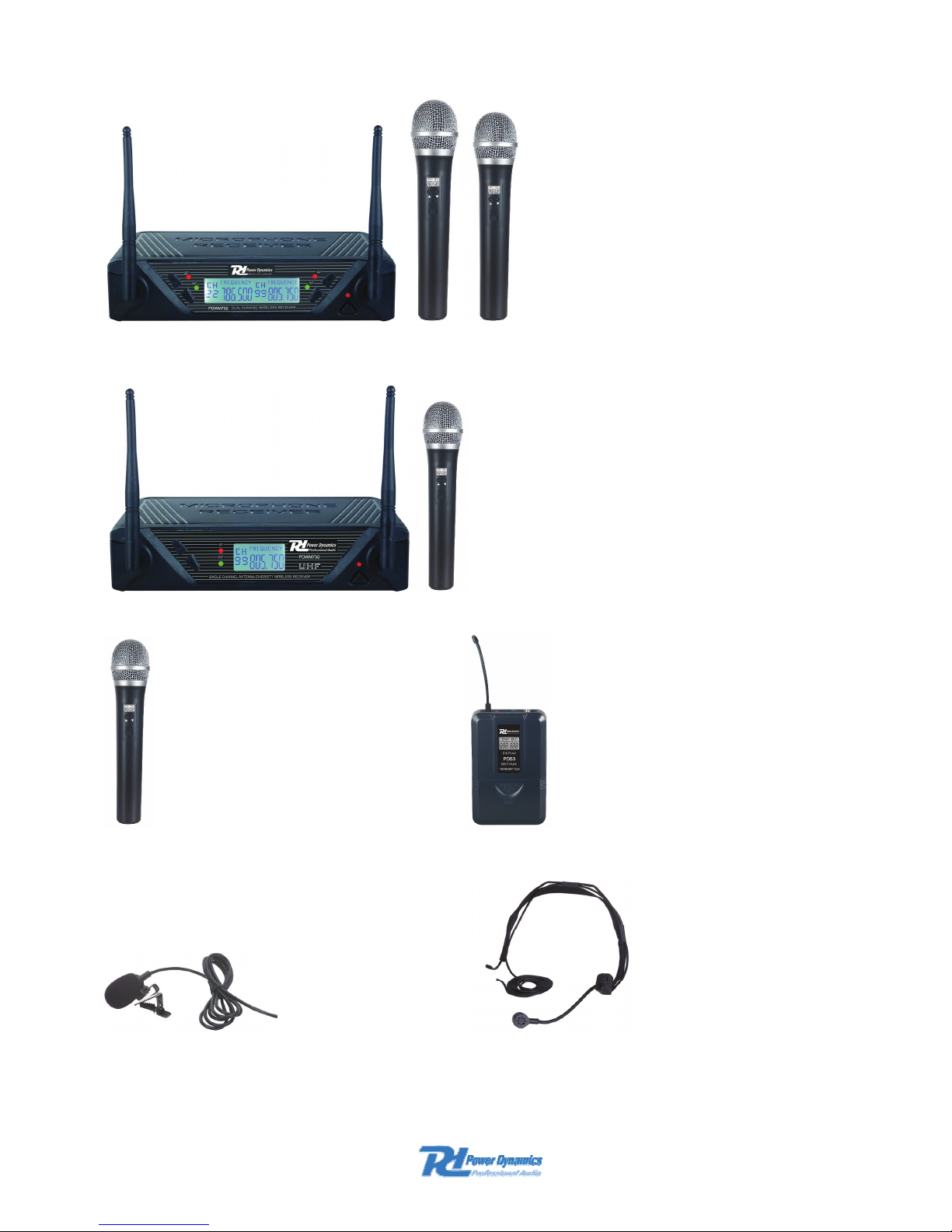
PDWM752 2x 16CH DUAL RECEIVER (179.150)
PDWM750 1x 16CH SINGLE RECEIVER (179.160)
ACCESSORIES:
PDM3 HANDHELD MICROPHONE (179.152) PDB3 BODYPACK (179.154)
PDT3 TIE CLIP MICROPHONE (179.158) PDH3 HEADSET (179.156)
Page 3

UK
Thank you very much for purchasing this Power Dynamics wireless microphone kit. Please read
this manual thoroughly before using this equipment
Warning
-
Always read the manual before using the product.
- Keep the manual so every new user can read it before using the product.
- Always keep the packaging. When a malfunction occurs, please send it in the original
packaging.
- Only for indoor use. Do not use in moistures places.
- Don’t expose to direct sunlight or heat sources.
- Don’t let small objects or fluids enter the housing. This may cause malfunction.
- Clean this unit with a dry cloth. Don’t use cleaning fluids or solvent.
- Unit contains no serviceable parts. Only the replacement parts named in this manual can
be changed by the user or servicing personnel.
- Never open the unit, service may only be done by qualified personnel.
- Never remove or place the mains plug in a socket with wet hands.
- Disconnect the unit from mains power before servicing.
- Condensation water can form while reusing, please let the unit reach the environmental
temperature before using it.
- Keep out of children’s reach.
- When the unit is damaged in a way that internal parts are visible. NEVER connect the unit
to a mains socket and NEVER switch the unit on. In this case, contact your supplier.
- When a lightning storm occurs, always disconnect this unit from the mains socket. Do the
same when the unit won’t or hasn’t be used for a long period of time.
- Using this unit might cause disturbance in insufficiently shielded equipment. This
disturbance might cause damage or accidents. Please check if there is any sensitive
equipment in close proximity of the unit before installing it.
To all residents of the European Union
Important environmental information about this product.
This symbol on the device or the package indicates that disposal of the device after its
lifecycle could harm the environment. Do not dispose the unit or batteries as unsorted
municipal waste, its should be taken to a specialized company or local recycling
service. If in doubt, contact your local waste disposal authorities.
SYSTEM FEATURE
1. Adopt the PLL-Synthesized control technic, 16 selectable UHF channel .
2. The UHF frequency range is 791-812MHz, avoiding the frequency interruption.
3. LCD information display.
4. Double noise squelch operation circuit and system will be higher efficient and much more
steady.
5. Use the dynamic type and Uni-directional cartridge, clear to show the sound.
6. High efficient and low consumption design.
7. Use the high extension antennas, the operating distance will reach 50m.
Page 4
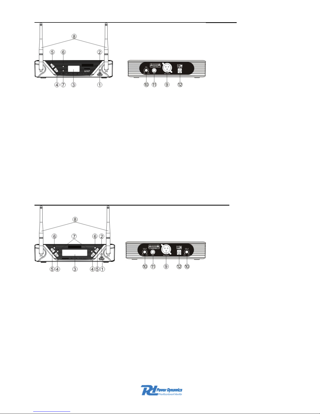
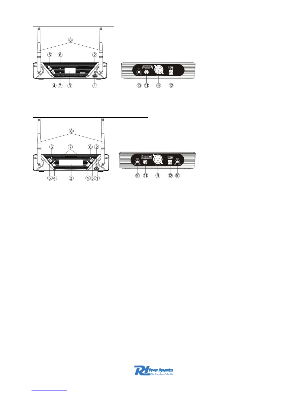
SINGLE CHANNEL RECEIVER FEATURES (PDWM750)
1. Power Switch: Power ON/OFF the receiver.
2. Power Indicator: Indicate the power ON/OFF.
3. LCD Information Display: Show the receiver frequency channel ect.
4. Down Function Button: Sets channel data.
5. Up Function Button: Sets channel data.
6. “AF” Audlo Level Indicator: Indicate the wireless system audio signal level.
7. “RF” signal indicator. It’s glows when the Receiver receive RF signal from Transmitter.
8. Antenna.
9. XLR Balanced Output Jack: Connect the audio cable from this jack to the input port of
amplifier, mixer.
10. Volume Knob: Adjust the volume output of receiver.
11. 6.3mm Audio Output Jack: Connect the audio cable from this jack to the input port of
amplifier, mixer.
12. Power Jack: Connect the AC/DC adapter to receiver.
DUAL CHANNEL RECEIVER FEATURES (PDWM752)
1. Power Switch: Power ON/OFF the receiver.
2. Power Indicator: Indicate the power ON/OFF.
3. LCD Information Display: Show the receiver frequency channel eel.
4. Down Function Button: Sets channel data.
5. Up Function Button: Sets channel data.
6. "AF”-Audio Level Indicator: Indicate the wireless system audio signal level.
7. "RF”- signal indicator: It’s glows when the Receiver receive RF signal from Transmitter.
8. Antenna.
9. XLR Balanced Output Jack: Connect the audio cable from this jack to the input port of
amplifier, mixer.
10. Volume Knob: Adjust the volume output of receiver.
11. 6.3mm Audio Output Jack: Connect the audio cable from this jack to the input port of
amplifier, mixer.
12. Power Jack: Connect the AC/DC adapter to receiver.
Page 5
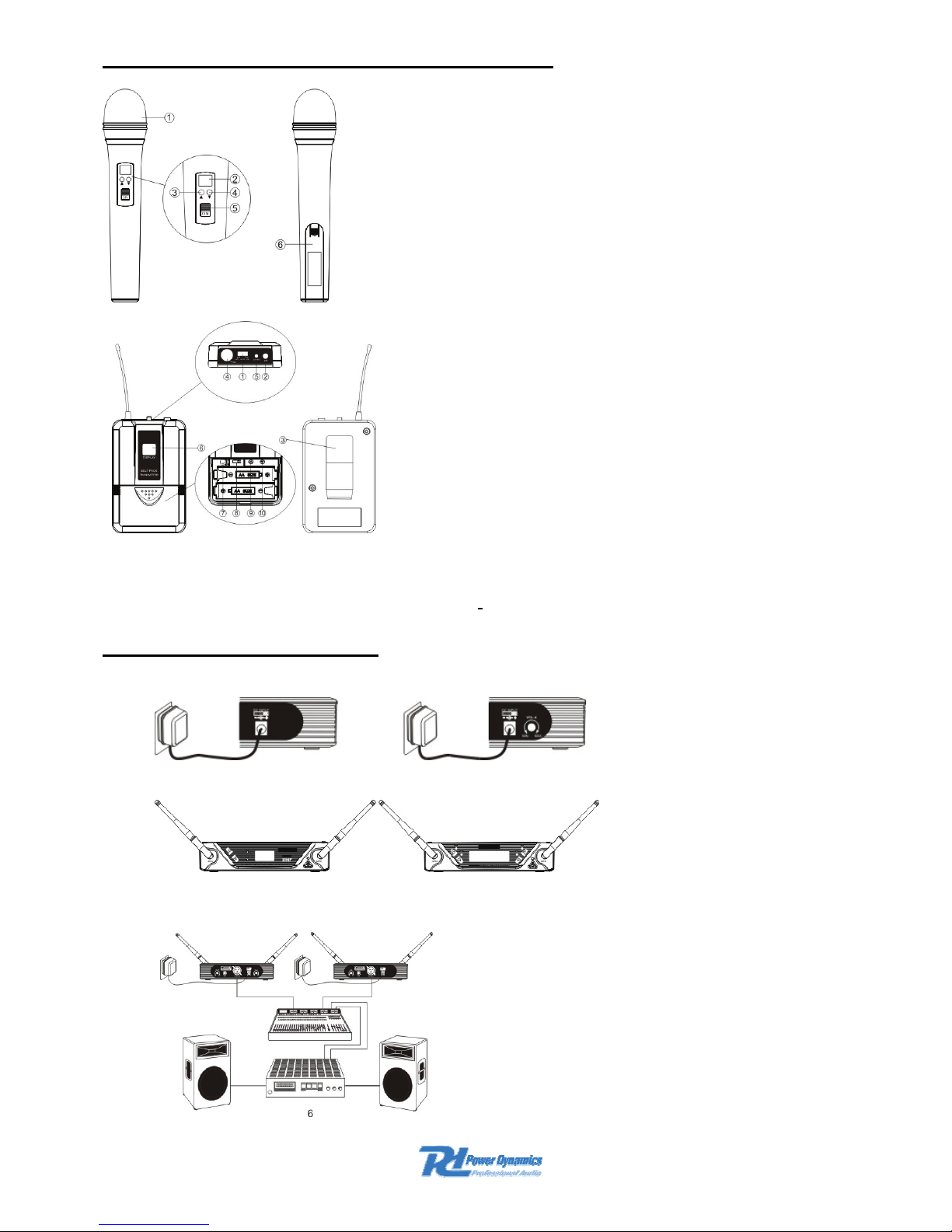
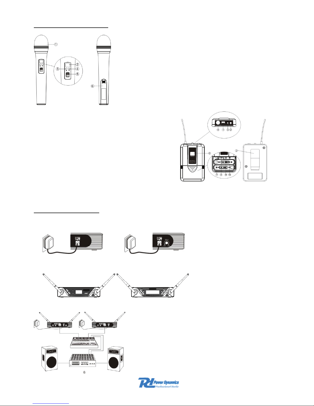
TRANSMITTER FUNCTION & FEATURES
1. Grille: Protects the cartridge and help reducing the breath
sounds and wind noise.
2. LCD Information Display: Show the transmitter frequency
channel eel.
3. Up Function Button: Sets channel data.
4. Down Function Button: Sets channel data.
5. Power and Audio Mute Switch.
6. Battery Cover: Open it to install the battery.
1. Power and Audio Mute Switch.
2. Antenna: Transmit the RF signal of transmitter.
3. Bell Clip: Attach the transmitter to the belt.
4. Audio Input Jack: It’s suitable for lavaliere
system/headset system.
5. Low Battery Indicator: Red light glows when it’s lack
of power and should renew the battery.
6. LCD Information Display: Show the transmitter
frequency channel ect.
7. Gain Adjusting Volume: Adjust the transmitter audio
input gain.
8. State Setting Switch: Set the using state of lavaliere
system(L)/headset system(H).
9. Up Function Button: Sets channel data.
10. Down Function Button: Sets channel data.
SYSTEM CONNECTIONS
1. Receiver Power Connection: Connect the AC adapter inlo the DC power connector on the
back of the receiver. Plug the AC adapter into a AC 230V~240VAC/50Hz outlet.
2. Antenna: Keep the position of antenna at a 45 angle from vertical, .(Shown as below)
3. Audio Connection: Connect the audio cable from the audio output on the receiver to the
input on your amplifier equipment.
Page 6
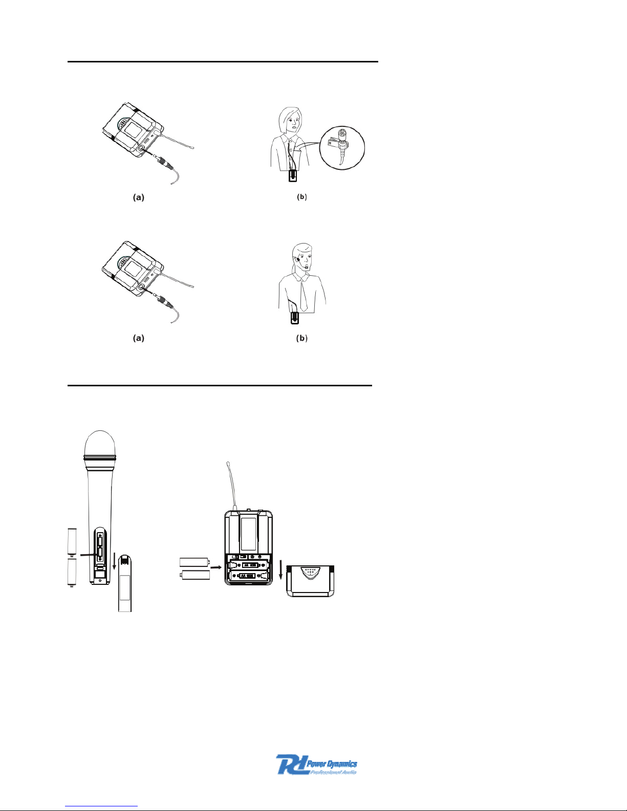
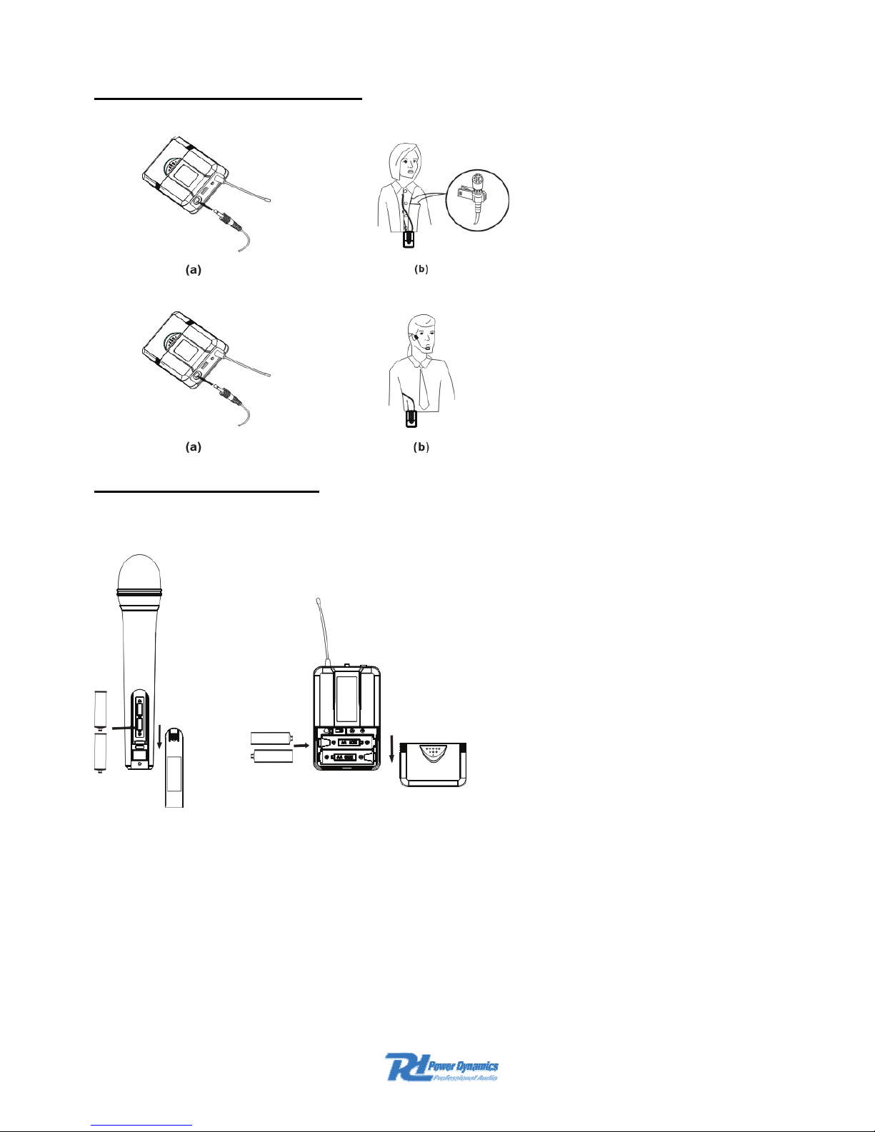
BODYPACK TRANSMITTER CONNECTION
1. Lavaliere Microphone Connection: Connect the connecter of supplied. Lavaliere
microphone to the connecting jack of transmitter (Shown as below).
Set the transmitter work state in wireless lavaliere system.
2. Headset Microphone Connection: Connect the connecter of supplied. Headset microphone
to the connecting jack of transmitter(Shown as below).
Set the transmitter work slate in wireless headset system.
TRANSMITTER BATTERY INSTALLATION
Battery Installation of Transmitter: Push open the battery cover, Insert the supplied batteries into
battery jar in polarity and cover the battery Cover.
Page 7

TROUBLESHOOTING
PROBLEM INDICATOR STATUS SOLUTION
No sound
Red transmitter position.
indicator is not flash
Slide transmitter POWER ON/OFF switch to ON
Make sure battery is Inserted properly, observing battery
("+/."). If battery is inserted
properly. replace with fresh battery.
No sound Red transmitter indicator Is flash Slide transmitter MUTE/ON switch to ON position
No sound Red receiver POWER light off.
Make sure ac adapter is securely plugged into electrical
outlet and into de input connector. Make sure ac
electrical outlet works and supplies proper voltage.
No sound
Receiver signal Indicators A/B
lights glowing
Turn up receiver volume control. Confirm that the output
connections from the receiver to the external equipment
are secure.
No sound
Receiver signal Indicators A/B
lights off, Transmitter and
receiver POWER lights glowing
Confirm transmitter’s and receiver’s frequencies match.
Move transmitter closer to receiver
Sound level differs
from level of a
cabled instrument
Receiver signal Indicators A/B
lights glowing
Adjust transmitter gain level to compessary
Adjust receiver volume as necessary
Sound level differs
with different guitars
Receiver signal Indicators A/B
lights glowing
Readjust transmitter gain level to compensate for
differences In guitar outputs
Distortion level
Increases gradually
Receiver Signal Indicators A/B
Lights and transmitter LOW
BATTERY light glowing
Replace transmitter battery
Bursts Of noise or
other audible radio
signals present
Signal Indicators A/B lights on
Identify potential sources of interference (other
RF·sources) and turn off, remove or use a wireless
system operating on a different frequency
Momentary loss of
sound as transmitter
is moved around.
performing area.
Receiver signal Indicators A/B
lights off when sound is lost
Reposition receiver and perform walkthrough test, if
audim dropouts persist mark "dead" spots and avoid
them during performance
SYSTEM SPECIFICATIONS
RF Carrier Frequency Range ..................... Approximately 791 to 812 MHZ
(Available freq. depend on applicable regulations in country where system is used).
Operating Range...........................................50m (under typical conditions)
Audio Frequency Response.........................................50Hz to 15kHz,±3dB
THD....................................................................................................... <1%
Operation temp. range ........................................................... -29°C to 74°C
..................................................NOTE:Battery characteristics may limit this
1622
Page 8

RECEIVER:
Power Requirements..........................................................230VAC adaptor
Power Requirements........................................13-15V DC nominal. 300mA
Signal/Noise Ratio .............................................................................>85dB
Border Upon Channel Rejection ........................................................>70dB
Image & Spurious Rejection...............................................................>70dB
Audio Output Level: ............................................................. 0dB +/-300mV
Receiving Sensitivity ......................................................................-105dBm
Dimensions ..................................................................... 185 x 145 x 43mm
HAND-HELD TRANSMITTER:
Power Requirements...................................................... 2x 1.5V AA battery
Nominal Current Drain ......................................................................<40mA
Modulation Tvpe ..................................................................................... FM
RF Output .......................................................................................>10dBm
Max Deviation .................................................................................. ±30kHz
Spurious Emission ............................................................................. >55dB
Dimensions ............................................................................ 238 x ø50mm
BODY-PACK TRANSMITTER:
Power Requirements...................................................... 2x 1.5V AA battery
Nominal Current Drain ......................................................................<40mA
Modulation Type ...................................................................................<FM
RF Output .......................................................................................>10dBm
Max Deviation ..................................................................................±30KHz
Spurious Emission ............................................................................. >55dB
Dimensions ....................................................................... 100 x 65 x 30mm
Page 9

NL
Hartelijk dank voor de aanschaf van deze Power Dynamics draadloze microfoonkit. Lees de
gebruiksaanwijzing aandachtig door alvorens het apparaat in bedrijf te stellen.
WAARSCHUWING
-
Lees altijd eerst de gebruiksaanwijzing voordat u een apparaat gaat gebruiken.
- Bewaar de handleiding zodat elke gebruiker hem eerst kan doorlezen.
- Bewaar de verpakking zodat u, indien het apparaat defect is, deze in de originele
verpakking kunt opsturen om beschadigingen te voorkomen.
- Apparaat alleen binnenshuis en in niet vochtige ruimtes gebruiken.
- Toestel niet in de buurt van warmtebronnen en of in direct zonlicht gebruiken.
- Zorg ervoor dat er geen kleine objecten of vloeistof in het toestel kunnen binnendringen.
- Toestel alleen reinigen met een licht vochtige stofvrije doek, geen reinigingsmiddelen of
oplosmiddelen gebruiken!
- Het toestel bevat buiten de in de gebruiksaanwijzing genoemde onderdelen geen
onderdelen die door de gebruiker vervangen of gerepareerd kunnen worden.
- Open nooit zelf het apparaat, laat reparaties over aan gekwalificeerd personeel.
- Verwijder of plaats de netvoeding nooit met natte handen respectievelijk uit en in het
stopcontact.
- Voordat het apparaat gerepareerd of onderhouden wordt, dient deze eerst losgekoppeld te
worden van de netspanning.
- Bij hergebruik kan condensatiewater gevormd worden; laat het apparaat eerst op
omgevingstemperatuur komen.
- Het apparaat buiten bereik van kinderen houden.
- Indien het apparaat dusdanig beschadigd is dat inwendige (onder)delen zichtbaar zijn,
mag de stekker NOOIT in het stopcontact worden geplaatst én het apparaat NOOIT
worden ingeschakeld. Neem in dit geval contact op met uw leverancier.
- Bij onweer altijd de adapter uit het stopcontact halen, zo ook wanneer het apparaat voor
langere tijd niet wordt gebruikt.
- Door het gebruik van dit product kan de werking van onvoldoende afgeschermde of
gevoelige elektronische apparatuur worden verstoord. Deze storing kan tot ongelukken of
beschadiging van uw apparatuur leiden. Controleer daarom voor het inschakelen van dit
apparaat of er geen apparatuur in de nabije omgeving is die gevoelig kan zijn voor
storingen.
SYSTEEM KENMERKEN
1. PLL-Synthesizer techniek, 16 UHF keuzekanalen.
2. Het UHF frequentie bereik is 790-812MHz.
3. LCD informatie display.
4. Dubbele squelch schakeling, zeer efficient en stabiel.
5. Dynamische en Uni-directionele microfoon
6. Laag energieverbruik.
7. Hoge antennes, hierdoor een bereik van +/- 50m mogelijk onder gunstige
omstandigheden.
8. Plug & Play
9. Voor podium gebruik en vele andere toepassingen.
Page 10
ONTVANGER (PDWM750)
DUBBELE ONTVANGER (PDWM752)
1. Aan/Uit toets
2. Aan/Uit Indicatie: Dit lampje brandt wanneer de ontvanger is aangesloten op het
stopcontact en de netschakelaar wordt ingedrukt.
3. LCD display : Laat het frequentiekanaal zien.
4. ▼ functie : Scroll functie om door kanaal gegevens te bladeren.
5. ▲ functie : Scroll functie om door kanaal gegevens te bladeren.
6. "AF”-Audioniveau Indicator.
7. "RF”- signaal indicator: Deze brandt wanneer de ontvanger een signaal ontvangt van de
zender.
8. Antenne.
9. XLR uitgangs connector: Gebalanceerde uitgang om aan te sluiten op de ingang van uw
mixer/versterker.
10. Volumeregelaar(s).
11. Jack Audio uitgang : Ongebalanceerde uitgang om aan te sluiten op de ingang van uw
mixer/versterker.
12. DC-aansluiting: Sluit de DC uitgang van de AC-adapter aan op de ontvanger en steek de
stekker in een stopcontact (Gebruik meegeleverde AC-adapter).
Page 11

ZENDER FUNCTIE & KENMERKEN
1. Beschermrooster/windkap : Voor bescherming van het
element.
2. LCD Display: Laat o.a. de frequenties en de kanalen zien.
3. ▲ Functie : Scroll functie om door kanaal gegevens te
bladeren.
4. ▼ Functie : Scroll functie om door kanaal gegevens te
bladeren.
5. Power / Mute toets: Aan/Uit toets + Mute functie.
6. Batterij deksel.
1. Aan/Uit toets + Mute functie.
2. Antenne
3. Riem Clip: Om aan de riem te bevestigen.
4. Audio-ingang voor dasspeld / hoofdband microfoon.
5. Lege batterij Indicatie: Batterijen vernieuwen wanneer
rode Led brandt.
6. LCD Display: Laat o.a. de frequenties en de kanalen
zien.
7. Gain: Niveauregelaar
8. Keuzeschakelaar: Om te kiezen tussen dasspeld- (L)
en hoofdband (H) microfoon.
9. ▲ Functie : Scroll functie om door kanaal gegevens
te bladeren.
10. ▼ Functie : Scroll functie om door kanaal gegevens te bladeren.
SYSTEEM AANSLUITINGEN
1. Netaansluiting : Sluit de adapter aan op het lichtnet (230Vac/50Hz) en plaats de
voedingsplug in de ontvanger op de achterzijde.
2. Antenna aansluiting: Sluit beide antennes aan (onder een hoek van 45°).
3. Audio aansluiting : Sluit de audio-apparatuur aan op de ontvanger.
Page 12
BODYPACK AANSLUITINGEN
1. Dasspeld microfoon aansluiting.
2. Hoofdband microfoon aansluiting.
BATTERIJEN PLAATSEN
Batterijen plaatsen: Plaats 2x AA (1.5V) Alkaline batterijen. (Controleer batterij polariteit)
Tips voor een maximale prestatie :
• De gebruiker dient de antenne’s van de ontvanger te kunnen zien.
• Zorg dat de afstand tussen zender en ontvanger zo kort mogelijk is.
• Vermijd plaatsing in de buurt van metalen constructies.
• Zorg er voor dat de batterijen altijd geladen zijn.
• Doe altijd een loop-test vooraf aan een presentatie, vermijd het wegvallen van een
microfoonsignaal op bepaalde plaatsen . Gebeurt dit toch dan dienen deze plaatsen (dead
spots) gemarkeerd te worden. Mijd deze dead-spots tijdens een presentatie.
Page 13

TROUBLESHOOTING
PROBLEEM INDICATIE STATUS MOGELIJKE OPLOSSING
Geen geluid
Rode
Led (zender) knippert niet
Schuif POWER ON/OFF schakelaar op de zender naar
“ON”.
Controleer de staat van de batterijen en vernieuw ze
eventueel. Denk aan de polariteit.
Geen geluid Rode Led (zender) knippert Schuif MUTE/ON schakelaar op de zender naar “ON”.
Geen geluid Aan/Uit Led is uit.
Zorg ervoor dat de netspanning 230Vac/50Hz deugdelijk
is aangesloten. Controleer of de adapter werkt.
Geen geluid Ontvanger Leds A/B branden
Regel het volume opnieuw in. Controleer of de ontvanger
en externe apparatuur deugdelijk zijn aangesloten.
Geen geluid
Ontvanger Leds A/B zijn uit.
Zender en ontvanger POWER
Leds zijn aan
Controleer of de ontvanger en de zender op dezelfde
frequentie staan.
Geluidsniveau
verschilt van dat van
een elektrisch
instrument
Ontvanger Leds A/B zijn aan Stel op de zender “gain level” opnieuw in.
Geluidsniveau
verschilt met
verschillende gitaren
Ontvanger Leds A/B zijn aan Stel op de zender “gain level” opnieuw in.
Vervormingsnivau
stijgt geleidelijk
Ontvanger Leds A/B zijn aan en
op zender brandt LOW
BATTERY
Vervang batterijen van de zender.
Ruis of andere
hoorbare signalen
Signaal Leds A/B gaan aan
Controleer of er andere zenders in de buurt zijn en
schakel ze zonodig uit. Ook kan een andere frequentie
gebruikt worden.
Geluid valt af en toe
weg als zender
wordt verplaatst
Ontvanger-Leds A/B gaan uit als
het geluid wegvalt.
Herpositioneer de ontvanger en doe een loop- test, als
het geluid weg blijft vallen dan de plaatsen waar dit
gebeurt markeren en deze mijden tijdens een
presentatie/uitvoering.
SYSTEEM SPECIFICATIES
Werkfrequentie ..................................................................790 tot 812 MHZ
(Beschikbare frequenties zijn afhankelijk van de richtlijnen in het land waar het systeem wordt gebruikt)
Bereik.......................................................... 50m (afhankelijk van condities)
Frequentie bereik ........................................................50Hz tot 15kHz,±3dB
THD....................................................................................................... <1%
Bedrijfstemperatuur............................................................... -29°C tot 74°C
E.r.p. ................................................................................................<10mW
Page 14

ONTVANGER:
Aansluitspanning..................................................................230VAC / 50Hz
Adapter-spanning sec. ................................................ 13-15V DC / 300mA
Signaal/Ruis verhouding ....................................................................>85dB
Kanaal rejectie ................................................................................... >70dB
Ongewenste rejectie .......................................................................... >70dB
Audio uitgangsniveau:.......................................................... 0dB +/-300mV
Gevoeligheid .................................................................................. -105dBm
Afmetingen......................................................................185 x 145 x 43mm
HAND-MICROFOON:
Voeding.......................................................................2x 1.5V AA batterijen
Nominale stroom...............................................................................<40mA
Modulatie Tvpe ....................................................................................... FM
RF uitgang ......................................................................................>10dBm
Max afwijking ................................................................................... ±30kHz
Ongewenste emissie.......................................................................... >55dB
Afmetingen............................................................................. 238 x ø50mm
BODY-PACK ZENDER:
Voeding.......................................................................2x 1.5V AA batterijen
Nominale stroom...............................................................................<40mA
Modulatie Type ....................................................................................... FM
RF uitgang ......................................................................................>10dBm
Max afwijking ...................................................................................±30KHz
Ongewenste emissie.......................................................................... >55dB
Afmetingen........................................................................100 x 65 x 30mm
Afgedankte artikelen !!
Raadpleeg eventueel www.nvmp.nl en/of www.vrom.nl
v.w.b. het afdanken van elektronische apparaten in het kader van de
WEEE-regeling. Vele artikelen kunnen worden gerecycled, gooi ze daarom niet bij het huisvuil maar lever ze in bij een
gemeentelijk depot of uw dealer. Lever ook afgedankte batterijen in bij uw gemeentelijk depot of bij de dealer, zie
www.stibat.nl
.
Voer zelf geen reparaties uit aan het apparaat; in elk geval vervalt de totale garantie. Ook mag het apparaat niet eigenmachtig worden
gemodificeerd, ook in dit geval vervalt de totale garantie. Ook vervalt de garantie bij ongevallen en beschadigingen in elke vorm t.g.v.
onoordeelkundig gebruik en het niet in acht nemen van de waarschuwingen in het algemeen en gestelde in deze gebruiksaanwijzing.
Tevens aanvaardt Power Dynamics geen enkele aansprakelijkheid in geval van persoonlijke ongelukken als gevolg van het niet
naleven van veiligheidsinstructies en waarschuwingen. Dit geldt ook voor gevolgschade in welke vorm dan ook.
1622
Momenteel te gebruiken in NL-B-D-I-E-S; wacht op Digitale Dividend
Band
Page 15

D
Herzlichen Glückwunsch zum Kauf dieser drahtlosen Funkmikrofonanlage von Power Dynamics.
Bitte lesen Sie diese Anleitung sorgfältig vor der Inbetriebnahme durch.
SICHERHEITSVORSCHRIFTEN:
- Vor Inbetriebnahme die Anleitung durchlesen.
- Für spätere Bezugnahme aufbewahren.
- Verpackung aufbewahren, so dass jederzeit ein sicherer Transport gewährleistet ist.
- Nur für Innengebrauch in trockenen Räumen.
- Vor Hitze schützen.
- Keine Flüssigkeiten oder Gegenstände durch die Belüftungsschlitze dringen lassen.
- Das Gerät nur mit einem leicht angefeuchteten, fusselfreien Tuch abwischen. Keine
Reinigungs- oder Lösungsmittel benutzen.
- Niemals das Gehäuse öffnen; Reparaturen nur von einem Fachmann ausführen lassen.
- Beim Abziehen des Steckers immer am Stecker ziehen, niemals an der Netzschnur.
- Bei Unwetter, sowie Nichtgebrauch das Netzgerät aus der Steckdose ziehen.
- Nach längerem Nichtgebrauch kann sich Kondenswasser im Gehäuse gebildet haben.
Lassen Sie das Gerät erst auf Raumtemperatur kommen.
- Wenn das Gerät sichtbar beschädigt ist, darf es NICHT an eine Steckdose angeschlossen
und NICHT eingeschaltet werden. Benachrichtigen sie in diesem Fall Power Dynamics
- Vor Kindern schützen.
- Stecker niemals mit nassen Händen anfassen.
- Vor Instandhaltungs- und Reparaturarbeiten erst den Stecker abziehen.
- Dieses Gerät kann bei empfindlichen oder ungenügend abgeschirmten Geräten Störungen
verursachen, die zu Pannen führen können. Bevor Sie dieses Gerät benutzen,
vergewissern Sie sich, dass sich in der näheren Umgebung keine Geräte befinden, die
gestört werden könnten.
SYSTEM EIGENSCHAFTEN
1. PLL-Synthesizer-Technologie, 16 UHF Kanäle.
2. Der UHF-Frequenzbereich ist 790-812MHz.
3. LCD Anzeige.
4. Dual Squelch-schaltung, hoch effizient und stabil.
5. Dynamisches Richtmikrofon
6. Niedriger Energieverbrauch.
7. Hohe Antennen, so dass ein Bereich von + / - 50m unter günstigen Umständen möglich ist.
8. Plug & Play
9. Für die Verwendung auf Bühnen und viele andere Anwendungen.
Page 16

EMPFÄNGER (PDWM750)
DUAL KANAL EMPFÄNGER (PDWM752)
1. Ein/Aus-Taste.
2. Betriebsanzeige: Leuchtet wenn der Empfänger mit dem Stromnetz verbunden ist und der
Netzschalter gedrückt wird.
3. LCD-Anzeige: Zeigt Frequenz / Kanal.
4. ▼ Funktion: Um durch Kanal-Daten zu blättern.
5. ▲ Funktion: Um durch Kanal-Daten zu blättern.
6. "AF”-Pegel-Anzeige.
7. "RF”-Pegel-Anzeige: Diese leuchtet wenn der Empfänger ein Signal vom Sender
empfängt.
8. Antenne.
9. XLR Ausgang: Symmetrischer Ausgang zum Anschluss an den Eingang eines Mixers /
Verstärkers.
10. Lautstärkeregler.
11. Audio Ausgang 6.35mm: Unsymmetrischer Ausgang zum Anschluss an den Eingang
eines Mixers / Verstärkers.
12. DC-Buchse: Verbinden Sie den DC-Ausgang des Netzteils (mitgeliefert) mit dem
Empfänger und stecken Sie den Netzstecker in eine Steckdose.
Page 17
SENDER FUNKTIONEN
1. Schutzgitter: Zum Schutz des Elements.
2. LCD-Anzeige: Zeigt u.a. die Frequenzen und Kanäle.
3. ▲ Funktion: Scroll-Funktion um durch Kanal-Daten zu
blättern.
4. ▼ Funktion: Scroll-Funktion um durch Kanal-Daten zu
blättern.
5. Power / Mute-Taste: Ein/Aus-Taste + Mute-Funktion.
6. Batteriefach
1. Power- und Mute Schalter.
2. Antenne
3. Gürtel- Clip
4. Für eine Krawattenmikrofonanlage /
Kopfbügelmikrofon System.
5. Warnanzeige bei niedriger Batteriespannung:
Batterien ersetzen wenn die rote LED leuchtet.
6. LCD-Anzeige: Zeigt u.a. die Frequenzen und
Kanäle.
7. Gain: Lautstärkeregler
8. Wahlschalter: Um zu wählen zwischen
Krawatten-(L) und Kopfbügel(H) -Mikrofon.
9. ▲ Function : Scroll-Funktion um durch Kanal-Daten zu blättern.
10. ▼ Function : Scroll-Funktion um durch Kanal-Daten zu blättern.
SYSTEM ANSCHLÜSSE
1. Verbinden Sie das Netztgerät mit dem Stromnetz (230VAC/50Hz) und schließen Sie die
Klinkenbüchse an auf der Rückseite.
2. Antennen-Anschluss: Die beide Antennen (Winkel=45°)mit den Einbaubüchsen verbinden.
45° Winkel
3. Audio-Anschluss: Die Audio-Geräte mit dem Empfänger verbinden.
Page 18

BODYPACK-SENDER ANSCHLÜSSE
1. Krawattenmikrofon Anschluß
2. Kopfmikrofon Anschluß.
BATTERIEN ERSETZEN
Batterien einlegen : 2x AA (1.5V) Alkaline Batterien. (Auf polarität achten)
Page 19

TROUBLESHOOTING
PROBLEM STATUSANZEIGE MÖGLICHE LÖSUNG
Kein Ton
Rote
Led (Sender) leuchtet nicht
Schiebe POWER ON/OFF-Schalter vom Sender in die
“ON” Position
Überprüfen Sie die Batterien und ersetzen Sie sie
gegebenenfalls. Bitte auf Polarität achten.
Kein Ton Rote Led (Sender) blinkt
Schiebe MUTE/ON-Schalter vom Sender in die “ON”
Position.
Kein Ton
Power Led Empfänger leuchtet
nicht
Stellen Sie fest daß das Netzgerät mit dem Stromnetz
(230Vac/50Hz) verbunden ist. Achten Sie darauf daß
das Netzgerät richtig funktioniert.
Kein Ton Empfänger Led A/B leuchten
Achten Sie darauf daß Empfänger und externe Geräte
richtig angeschlossen sind. Lautstärkeregler einstellen.
Kein Ton
Empfánger Led A/B leuchten
nicht. Sender- und Empfänger
POWER -Led leuchten
Achten Sie darauf daß Empfänger und Sender auf der
gleichen Frequenz arbeiten
Schallpegel anders
als bei einem
elektrischen Gerät
Empfänger Led A/B leuchten Lautstärke Pegel vom Sender erneut einstellen
Schallpegel anders
als bei
verschiedenen
Gitarren
Empfänger Led A/B leuchten Lautstärke Pegel vom Sender erneut einstellen
Die Verzerrung
steigt allmählich
Empfänger Led A/B und Sender
Anzeige “LOW BATTERY”
leuchten
Sender-Batterien ersetzen.
Geräusche oder
andere akustische
Signale
Signal Led A/B leuchten
Überprüfen Sie ob andere Sender in der Nähe sind (und
wenn nötig ist ausschalten). Auch kann eine andere
Frequenz verwendet werden.
Ton fällt aus wenn
Sender umgeräumt
wird
Empfänger-Led A/B leuchten
nicht wenn Ton ausfällt
Neu-positionieren Sie den Empfänger und führen Sie
einen Geh-Test vor; wenn der Ton noch immer ausfällt
markieren Sie diese Stellen und vermeiden Sie diese
während einer Präsentation.
TECHNISCHE DATEN
Das zur Verfügung stehende Frequenzspektrum ist 790-812MHz (für jedes Land je nach den örtlichen Vorschriften).
Reichweite ................................................... 50m (je nach den Umständen)
Frequenz Bereich....................................................... 50Hz bis 15kHz,±3dB
THD....................................................................................................... <1%
Betriebstemperatur ...............................................................-29°C bis 74°C
Strahlungsleistung. ..........................................................................<10mW
Page 20

EMPFÄNGER:
Versorgung ..........................................................................230VAC / 50Hz
Netzgerät-spannung sek. ............................................ 13-15V DC / 300mA
Störabstand........................................................................................>85dB
Kanal Rejection..................................................................................>70dB
(Ungewünschte) Rejection................................................................. >70dB
Audio Ausgangspegel: ......................................................... 0dB +/-300mV
Empfindlichkeit...............................................................................-105dBm
Abmessungen ................................................................. 185 x 145 x 43mm
HAND-MIKROFON:
Speisung......................................................................2x 1.5V AA batterien
Nominal Strom .................................................................................. <40mA
Modulation ............................................................................................. FM
RF ausgang ....................................................................................>10dBm
Max Deviation .................................................................................. ±30kHz
(Ungewünschte) Emission .................................................................>55dB
Abmessungen ........................................................................ 238 x ø50mm
BODY-PACK SENDER:
Speisung......................................................................2x 1.5V AA batterien
Nominal Strom .................................................................................. <40mA
Modulation .............................................................................................. FM
RF ausgang ....................................................................................>10dBm
Max Deviation ..................................................................................±30KHz
(Ungewünschte) Emission .................................................................>55dB
Abmessungen ................................................................... 100 x 65 x 30mm
Dieses Produkt darf am Ende seiner Lebensdauer nicht über den normalen Haushaltsabfall entsorgt werden,
sondern muss an einem sammelpunkt für das Recycling abgegeben werden. Die Werkstoffe sind gemäß
ihrer Kennzeichnung wieder verwertbar. Hiermit leisten Sie einen wichtigen Beitrag zum Schutze unserer
Umwelt.
Lithiumbatterien und Akkupacks sollten nur im entladenen Zustand in die Altbatteriesammelgefäße bei Handel und
bei öffentlich-rechtlichen Entsorgungsträgern gegeben werden. Bei nicht vollständig entladenen Batterien Vorsorge
gegen Kurzschlüß treffen durch Isolieren der Pole mit Klebestreifen.
Reparieren Sie das Gerät niemals selbst und nehmen Sie niemals eigenmächtig Veränderungen am Gerät vor. Sie verlieren
dadurch den Garantieanspruch.
Der Garantieanspruch verfällt ebenfalls bei Unfällen und Schäden in jeglicher Form, die durch unsachgemäßen Gebrauch und
Nichtbeachtung der Warnungen und Sicherheitshinweise in dieser Anleitung entstanden sind.
Power Dynamics ist in keinem Fall verantwortlich für persönliche Schäden in Folge von Nichtbeachtung der
Sicherheitsvorschriften und Warnungen. Dies gilt auch für Folgeschäden jeglicher Form.
1622
Derzeit für gebrauch in NL-B-D-I-E-S ; Warte auf „Digital Dividend
Band“
Page 21

CE Declaration of Conformity
Importer: TRONIOS BV
Bedrijvenpark Twente 415
7602 KM - ALMELO
Tel : 0031546589299
Fax : 0031546589298
The Netherlands
Product number: 179.150 & 179.160
Product Description:
Power Dynamics PDWM, UHF Wireless Microphone System
Regulatory Requirement: EN 60065
EN 50371
EN 301489-1
EN 300422-1
The product met the requirements stated in the above mentioned Declaration(s).
This certificate does not cover the aspects that may be relevant such as performance and
fitness for purpose.
ALMELO,
08-12-2010
Signature
Page 22

Specifications and design are subject to change without prior notice..
www.tronios.com
Copyright © 2010 by TRONIOS the Netherlands
 Loading...