

Page 1
V1.1
WIRELESS MICROPHONE SYSTEMS
179.126-2x16Channel
179.130-2x16Channel
179.133-1x16Channel
Instruction Manual
Gebruiksaanwijzing
Gebrauchsanleitung
Page 2

UK
Thanks for purchasing this product, please read this instruction carefully so that can understand
how to operate the product of style you bought correctly. Please store this instruction in a safe
place after reading as a reference in the future. This series of professional wireless microphone
system used a super steady PLL-synthesized control technique and match with the high efficient,
low consumption discharging technique.
Warning
- Always read the manual before using the product.
- Keep the manual so every new user can read it before using the product.
- Always keep the packaging. When a malfunction occurs, please send it in the original
packaging.
- Only for indoor use. Do not use in moistures places.
- Don’t expose to direct sunlight or heat sources. Don’t block ventilation openings.
- Don’t let small objects or fluids enter the housing. Don’t put candles on it. This may cause
malfunction.
- Clean this unit with a dry cloth. Don’t use cleaning fluids or solvent.
- Unit contains no serviceable parts. Only the replacement parts named in this manual can be
changed by the user or servicing personnel.
- Never open the unit, service may only be done by qualified personnel.
- Never remove or place the mains plug in a socket with wet hands.
- Disconnect the unit from mains power before servicing.
- Condensation water can form while reusing, please let the unit reach the environmental
temperature before using it.
- Keep out of children’s reach.
- When the unit is damaged in a way that internal parts are visible. NEVER connect the unit to
a mains socket and NEVER switch the unit on. In this case, contact your supplier.
- When a lightning storm occurs, always disconnect this unit from the mains socket. Do the
same when the unit won’t or hasn’t be used for a long period of time.
- Using this unit might cause disturbance in insufficiently shielded equipment. This disturbance
might cause damage or accidents. Please check if there is any sensitive equipment in close
proximity of the unit before installing it.
FOREWORD
Your new series of wireless system is designed to give you the best of both sound reinforcement
words, the freedom of wireless system, and the excellent quality. This manual covers each of the
series system.
This product is for licensefree use in all EU member states.
Do not attempt to make any repairs yourself. This would invalid your warranty. Do not make any changes to the
unit. This would also invalid your warranty. The warranty is not applicable in case of accidents or damages
caused by inappropriate use or disrespect of the warnings contained in this manual. Power Dynamics cannot
be held responsible for personal injuries caused by a disrespect of the safety recommendations and warnings.
This is also applicable to all damages in whatever form.
Page 3
SYSTEM FEATURES
A. Adopt the PLL-Synthesized control technical, 1x16 and 2x16 UHF channels.
B. The UHF frequency range is 863-865MHz.
C. LCD information display.
D. CPU :Fully computerized, processing function of frequency selection, display or lock.
E. Noise squelch operation circuit and system will be higher efficient and much more steady.
F. Sync IR learning and data system for channel selection.
G. Diversity receiver.
H. AFS- channel searching
SYSTEM SETUP
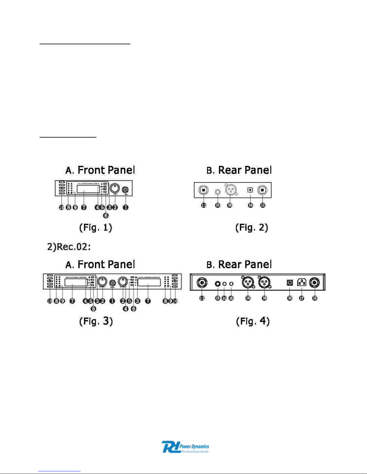
179.126 UHF 2x 16 ch with hand-held and headset system
179.130 UHF 2x 16 ch with two handheld mics
179.133 UHF 1x 16 ch with one handheld mic
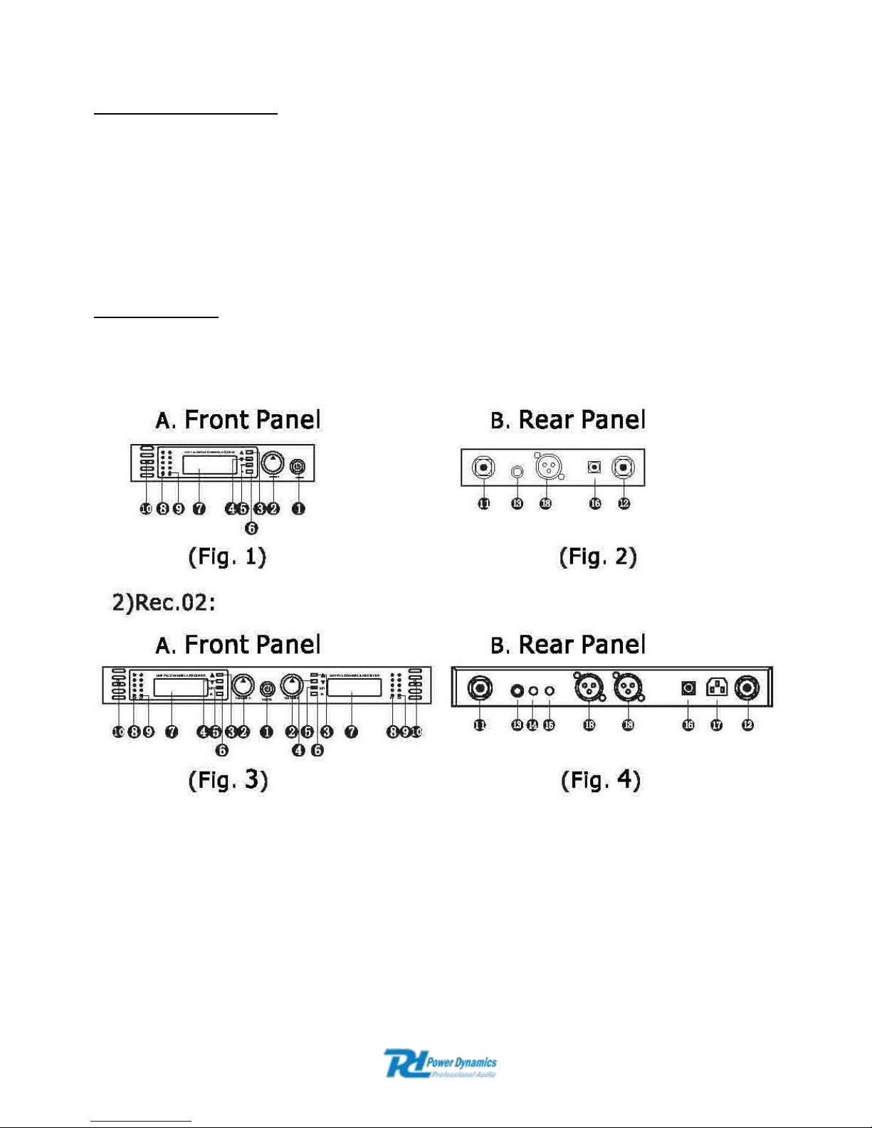
1. Power switch to switch ON/OFF the system
2. Volume : To control the volume
3. Up Key
4. Down Key
5. Set Key: Menu control settings and confirm key
6. Infrared “transmit” key
7. LCD Screen display, displaying frequency, channel, RF signal,audio signal, antenna state
8. RF: signal receipt strong or weak
9. AF: signal volume strong or weak
10. IR emission LED
11. ANT-A
12. ANT-B
Page 4
13. Mix out: Output jack for both channels
14. Output jack channel B
15. Output jack channel A
16. Power inlet, 12-15Vdc
17. AC power input
18. Balance outputs
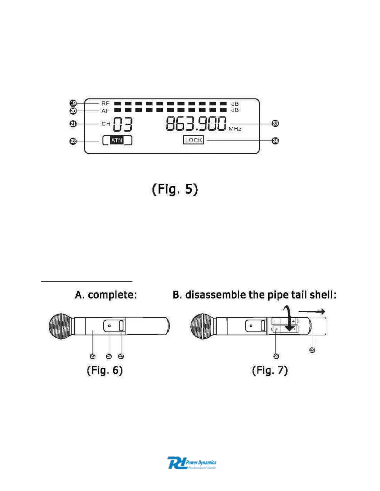
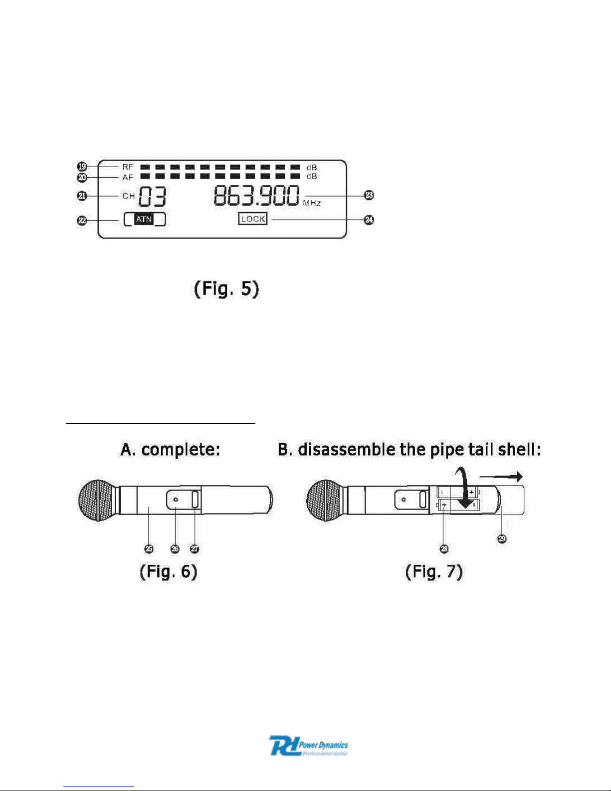
Receiver LCD display panel:
19. RF signal receipt display
20. AF signal volume display
21. Display the current frequency channel
22. RF antenna signal status
23. Frequency display
24. LOCK: Pressing keys will not change the current feature setting of the system
HANDHELD TRANSMITTER
25. Tube body: the top contains the element, the tube the transmitting pcb, battery and
antenna.
26. Power LED: Lights when the transmitter is activated.
27. Power switch
28. Battery compartment, remove batteries in case of long time no use (prevent leakage).
29. IR signal emission LED. To learn the IR system the ideal distance is 10 cm.
Page 5
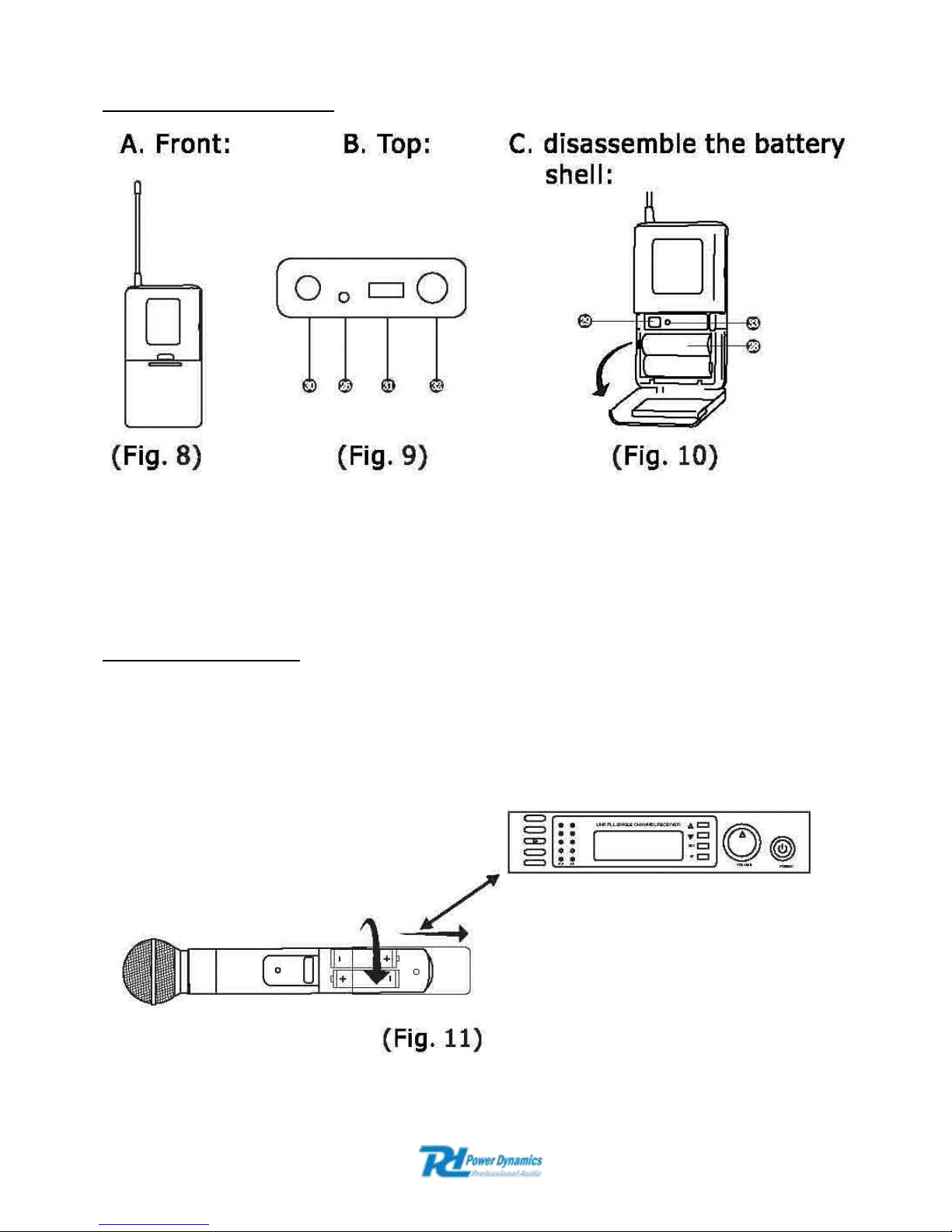
BODYPACK TRANSMITTER
30. Antenna.
31. Power Button
32. Input Connector: It is TA3 PINS connector; It is suitable for the lavaliere microphones
system/ Headset microphone systems.
33. Lavalier/Headset audio level switch
IR-------------IR SETTING
Turn on the transmitter and the receiver, set the desired channel or the desired frequency on the
receiver. Keep the transmitter + / - 10cm from the IR LED on the receiver, press the IR button,
onto the display "SEND" will flash three times. If a connection is established “Auto” will be
continuously lit and the RF signal display will display the strength of the signal. If not, you should
try it again!
Page 6

LOCK-------------LOCK SETTING
Press SET and DOWN key at the same time to lock. After locked press any key will not change
the settings of the system.
179.126 and 179.130 : Press both the left and right SET key simultaneously of both receivers.
179.133: Hold down the SET key and press the DOWN key. Follow the above procedure again to
the system “unlock”.
AFS:
This AFS channel searching system simplifies the operating procedure.
Turn on the system. Press SET and UP key at the same and the system will automatically scan
the frequency.
OPERATION:
Turn off the system first, turn down the receivers volume to the minimum and then turn on the
receiver, CPU initializes, the LCD screen begins to display and the system reverts to the last
shutdown’s state!
Tune to the desired frequency of the receiver and observe the RF- and AF signal level. If the
signal level is displayed it means the receiver has interference from other signals or noise. The
system has a mute circuit to avoid interference noise. If interfere with each other occurs it is
recommended to use other frequencies.
If the system is turned on look at the transmitter and receiver’s frequency, if they do not operate
on the same frequency pls use the IR function → see IR setting!
Then the receiver display shows RF signal level value, the antenna status will display antenna A
or B. Adjust the volume to the desired level.
Volume adjustment:
Adjust the receiver’s volume to the 12 o’clock position, then adjust the volume of the amplifier or
mixer to a desired level.
If the receiver volume has been adjusted too loud the amplifier will produce a saturated distortion
which will blow the amplifier or/and the loudspeaker(s)!
Best acoustics:
1. You should always see the receiver antenna from your transmitter location.
2. The distance between transmitter and receiver should be as short as possible.
3. If the receiver has two antennas, they should be adjusted 45° with a vertical line.
4. Keep the antennas away from metal surfaces and shelter.
5. Let the antennas not contact or cross each other.
6. Before using the system during the presence of public do a test to find out where the “dead
spots” are. Avoid these spots when operational.
Page 7

Specifications:
Freq. range ................................................ 863-865MHz
Oscillation mode ........................................ VCO + PLL
Deviation .................................................... +/- 45kHz
Channel width ............................................ 30MHz
S/N ratio ..................................................... >105dB
THD ........................................................... <0.3%/1kHz
Freq response ............................................ 50Hz – 18kHz
Receiver:
Intermediate freq ........................................ 72.1MHz/10.7MHz
Antenna input ............................................. 50 Ohms/TNC
Sensitivity ................................................... 15dBuV
RF squelch ................................ ................. >80dB
Transmitter:
Input max ................................................... 130dB
Cartridge .................................................... Condenser/Dynamic(Optional)
Battery........................................................ 2*AA
TROUBLESHOOTING:
Electric products must not be put into household waste. Please bring them to a recycling centre. Ask your local
authorities or your dealer about the way to proceed. The specifications are typical. The actual values can slightly
change from one unit to the other. Specifications can be changed without prior notice.
Problem
Solution
No sound: Status: receiver RF monitor
does not light up.
1. Check mic power switch is in “ON”
position.
2. Check antenna connection.
3. Check obstructions between mic
and receiver.
4. Check battery polarity.
No sound: Status: Both RF and AF
display are normal.
1. Check loudspeaker connection.
2. Check receiver volume knob is in
minimum position.
No sound: Status: RF display normal and
AF doesn’t work.
1. Check the cartridge of the mic.
2. Check power of the mic.
Noise or interference
1. Eliminate RF interferences
2. Check connection cords
3. Two mics use same frequencies
4. Check antenna position
5. Stay close to the receiver
6. Check polarity of the batteries
After shutdown the mic, the receiver has
noise
Adjust the receiver and antenna positions
again.
Sound is occasionally weak
Avoid “dead spots” .
Transmitter is not working at all
Check the batteries
This product should licencefree be used in all EU countries!
Page 8

NL
Hartelijk dank voor de aanschaf van deze Power Dynamics draadloze microfoonkit. Lees de
gebruiksaanwijzing aandachtig door alvorens het apparaat in bedrijf te stellen.
WAARSCHUWING
- Lees altijd eerst de gebruiksaanwijzing voordat u een apparaat gaat gebruiken.
- Bewaar de handleiding zodat elke gebruiker hem eerst kan doorlezen.
- Bewaar de verpakking zodat u, indien het apparaat defect is, deze in de originele verpakking kunt
opsturen om beschadigingen te voorkomen.
- Apparaat alleen binnenshuis en in niet vochtige ruimtes gebruiken.
- Toestel niet in de buurt van warmtebronnen en of in direct zonlicht gebruiken.
- Zorg ervoor dat er geen kleine objecten of vloeistof in het toestel kunnen binnendringen.
- Toestel alleen reinigen met een licht vochtige stofvrije doek, geen reinigingsmiddelen of
oplosmiddelen gebruiken!
- Het toestel bevat buiten de in de gebruiksaanwijzing genoemde onderdelen geen onderdelen die
door de gebruiker vervangen of gerepareerd kunnen worden.
- Open nooit zelf het apparaat, laat reparaties over aan gekwalificeerd personeel.
- Verwijder of plaats de netvoeding nooit met natte handen respectievelijk uit en in het stopcontact.
- Voordat het apparaat gerepareerd of onderhouden wordt, dient deze eerst losgekoppeld te worden
van de netspanning.
- Bij hergebruik kan condensatiewater gevormd worden; laat het apparaat eerst op
omgevingstemperatuur komen.
- Het apparaat buiten bereik van kinderen houden.
- Indien het apparaat dusdanig beschadigd is dat inwendige (onder)delen zichtbaar zijn, mag de
stekker NOOIT in het stopcontact worden geplaatst én het apparaat NOOIT worden ingeschakeld.
Neem in dit geval contact op met uw leverancier.
- Bij onweer altijd de adapter uit het stopcontact halen, zo ook wanneer het apparaat voor langere
tijd niet wordt gebruikt.
- Door het gebruik van dit product kan de werking van onvoldoende afgeschermde of gevoelige
elektronische apparatuur worden verstoord. Deze storing kan tot ongelukken of beschadiging van
uw apparatuur leiden. Controleer daarom voor het inschakelen van dit apparaat of er geen
apparatuur in de nabije omgeving is die gevoelig kan zijn voor storingen.
Afgedankte artikelen !!
Raadpleeg eventueel www.nvmp.nl en/of www.vrom.nl v.w.b. het afdanken van elektronische apparaten in het kader van de
WEEE-regeling. Vele artikelen kunnen worden gerecycled, gooi ze daarom niet bij het huisvuil maar lever ze in bij een
gemeentelijk depot of uw dealer. Lever ook afgedankte batterijen in bij uw gemeentelijk depot of bij de dealer, zie
www.stibat.nl .
Voer zelf geen reparaties uit aan het apparaat; in elk geval vervalt de totale garantie. Ook mag het apparaat niet
eigenmachtig worden gemodificeerd, ook in dit geval vervalt de totale garantie. Ook vervalt de garantie bij ongevallen en
beschadigingen in elke vorm t.g.v. onoordeelkundig gebruik en het niet in acht nemen van de waarschuwingen in het
algemeen en gestelde in deze gebruiksaanwijzing. Tevens aanvaardt Power Dynamics geen enkele aansprakelijkheid in
geval van persoonlijke ongelukken als gevolg van het niet naleven van veiligheidsinstructies en waarschuwingen. Dit geldt
ook voor gevolgschade in welke vorm dan ook.
Dit product mag vergunningvrij worden gebruikt in alle landen van de EU.
Page 9
SYSTEEM KENMERKEN
A. PLL-Synthesizer, 1x16 en 2x16 UHF kanalen.
B. De UHF werkfrequentie is 863-865MHz.
C. LCD-informatie display.
D. CPU :Volledig geautomatiseerde frequentie instelling, display of lock.
E. Ruis squelch schakeling, het system werkt hierdoor efficienter en stabieler.
F. Sync IR “leer-functie” en data systeem voor kanaalkeuze.
G. Diversity ontvanger.
H. AFS- kanaalzoeker
I. Geschikt voor 19” rack
SYSTEEM SETUP
179.126 UHF 2x 16 kanaals met handmicrofoon en headset systeem
179.130 UHF 2x 16 kanaals met twee handmicrofoons
179.133 UHF 1x 16 kanaals met één handmicrofoons
1. Aan/Uit schakelaar
2. Volumeregelaar
3. Up toets
4. Down toets
5. Set toets: Menu bedientoets en toets om op te slaan
6. Infrarood “zend” toets
7. LCD Scherm display, geeft frequentie, kanaal, RF signaal, audio signaal en antenne
status weer.
8. RF: ontvangst signaal weergave sterk of zwak
9. AF: geluidssterkte signaal weergave sterk of zwak
10. IR emissie LED
11. ANT-A
12. ANT-B
Page 10

13. Mix out: Uitgangsjack voor beide kanalen
14. Uitgangsjack voor kanaal B
15. Uitgangsjack voor kanaal A
16. 12-15Vdc aansluiting
17. 220-240Vac aansluiting
18. Gebalanceerde aansluitingen
Ontvanger LCD display:
19. RF: ontvangst signaal weergave sterk of zwak
20. AF: geluidssterkte signaal weergave sterk of zwak
21. Gebruikt frequentiekanaal
22. RF antenne signaal status
23. Frequentie weergave
24. LOCK: De huidige functie-instelling v.h. systeem kan niet meer veranderd worden
HANDMICROFOON (ZENDER )
25. Behuizing: Bovenin zit het element, daaronder de zender, batterij en antenne.
26. Power LED: Brandt als de zender werkt.
27. Aan/Uit schakelaar .
28. Batterijvak, verwijder de batterijen bij langdurig niet gebruik (voorkom lekkage).
29. IR signaal-ontvangst . Een infrarood linkfunctie om de zender en de ontvanger
electronisch aan elkaar te koppelen, de ideale afstand is 10 cm om de zender van de
ontvanger te houden .
Page 11

BODYPACK ZENDER
30. Antenne.
31. Aan/Uit schakelaar bodypack.
32. Ingang 3 PINS connector; geschikt voor lavalier microfoons / Headset microfoon systems.
33. Lavalier/Headset niveau schakelaar
IR-------------IR INSTELLING
Zet de zender en de ontvanger aan, stel het gewenste kanaal of de gewenste frequentie in op de
ontvanger. Houd de zender +/- 10cm van de IR LED op de ontvanger, druk op de IR toets, in de
display zal “SEND” 3 keer knipperen. Als er een verbinding tot stand komt zal Auto continu gaan
branden en de RF signaal weergave zal uitslaan. Als dit niet gebeurt dient u het opnieuw te
proberen!
Page 12

LOCK------LOCK INSTELLING
Om de instellingen vast te zetten (locken) volg onderstaande procedures. Hierna functioneert
geen enkele toets meer! Het systeem is op slot gezet en kan dan niet zomaar gewijzigd worden.
179.126 en 179.130:
Druk zowel de linkse SET toets als de rechtse SET toets van beide ontvangers tegelijkertijd in
179.133:
Houd de SET toets ingedrukt en druk dan op de DOWN toets
Volg tevens bovenstaande procedure weer om het systeem te “unlocken”
AFS:
Dit AFS kanaalzoek- systeem vergemakkelijkt de werkwijze.
Schakel het systeem in. Druk de SET en UP toets en het systeem zal automatisch de frequenties
gaan scannen.
BEDIENING:
Schakel het systeem UIT, draai het volume van de ontvanger naar een minimum en schakel het
systeem weer in en de CPU initialiseert, het LCD scherm licht op en het systeem komt terug in
de status waarin het is afgesloten!
Zoek de gewenste frequentie op de ontvanger op en let op het het RF- en AF signaalniveau. Als
er een signaal in de display verschijnt duidt dit op een interferentie van andere signalen of ruis.
Het systeem beschikt over een mute schakeling om de ruis uit te schakelen. Indien er sprake is
van interferentie t.g.v. de andere microfoon zoek dan voor deze microfoon een andere frequentie
op.
Als het systeem is ingeschakeld controleer dan de frequenties van de zender en de ontvanger,
als ze niet op dezelfde frequenties werken is de zender niet aangepast aan de ontvanger, zie de
IR functie → IR------IR instelling! hierboven.
De display op de ontvanger laat de waarde van het RF signaal zien, de antenne-status zal
antenne A of B weergeven. Zet het volume op de gewenste sterkte.
Volume regeling:
Zet het volume van de ontvanger in de 12 uurs positie (middenstand), zet dan het volume van de
versterker of de mixer op het gewenste niveau.
Als het volume van de ontvanger te hoog staat zal de versterker een vervormd signaal laten
horen hetgeen een defecte versterker en/of luidspreker(s) tot gevolg kan hebben!
Beste akoestiek:
1. U dient altijd de antenne van de ontvanger te kunnen zien vanaf uw zenderpositie.
2. De afstand tussen zender en ontvanger dient zo kort mogelijk te zijn.
3. Als de ontvanger twee antenne’s heeft, dienen ze onder 45° te worden gezet.
4. Houd de antenne’s verwijderd van metalen objecten.
5. De antenne’s mogen elkaar niet raken of elkaar kruisen.
6. Voordat u het systeem in het openbaar gebruikt doe dan eerst een test om uit te zoeken
waar zich de “dead spots” (plaatsen waar een slechte verbinding met de ontvanger plaats
vindt) bevinden. Vermijd deze plaatsen tijdens uw optreden.
Page 13

Specificaties:
Werkfrequenties ......................................... 863-865MHz
Oscillatie mode .......................................... VCO + PLL
Deviatie ...................................................... +/- 45kHz
Kanaalbreedte ............................................ 30MHz
S/R verhouding .......................................... >105dB
THD ........................................................... <0.3%/1kHz
Freq bereik ................................ ................. 50Hz – 18kHz
Ontvanger:
Midden frequentie ...................................... 72.1MHz/10.7MHz
Antenne ingang .......................................... 50 Ohms/TNC
Gevoeligheid .............................................. 15dBuV
RF squelch ................................ ................. >80dB
Zender:
Ingang max ................................................ 130dB
Cartridge .................................................... Condenser/Dynamisch(Optie)
Batterij ........................................................ 2*AA
PROBLEEMOPLOSSING:
Probleem
Oplossing
Geen geluid : Status: Geen RF
signaalsterkte in de display.
1. Controleer of de microfoon
aanstaat.
2. Controleer antenne aansluiting.
3. Controleer of zich objecten
bevinden tussen microfoon en
ontvanger.
4. Controleer polariteit batterijen.
Geen geluid : Status: Zowel RF als AF
signaalsterkte in de display.
1. Controleer luidsprekeraansluiting.
2. Check ontvanger-volumeknop staat
in de min. stand.
Geen geluid: Status: RF signaalsterkte in
de display maar geen AF signaalsterkte.
A. Check de cartridge van de mic.
B. Check batterijen/power van de mic.
Ruis of interferentie
1. Elimineer RF interferenties
2. Check aansluitkabels
3. Twee mics staan op dezelfde
frequentie
4. Check antenne positive(s)
5. Blijf dicht bij de ontvanger
6. Check polariteit van de batterijen
Na het uitschakelen van de microfoon,
wordt een ruissignaal gehoord
Stel de ontvanger en antenne posities
opnieuw in.
Af en toe een zwak signaal
Vermijd “dead spots” .
Zender werkt helemaal niet
Controleer de batterijen
Page 14

D
Herzlichen Glückwunsch zum Kauf dieser drahtlosen Funkmikrofonanlage von Power Dynamics.
Bitte lesen Sie diese Anleitung sorgfältig vor der Inbetriebnahme durch.
SICHERHEITSVORSCHRIFTEN:
- Vor Inbetriebnahme die Anleitung durchlesen.
- Für spätere Bezugnahme aufbewahren.
- Verpackung aufbewahren, so dass jederzeit ein sicherer Transport gewährleistet ist.
- Nur für Innengebrauch in trockenen Räumen.
- Vor Hitze schützen.
- Keine Flüssigkeiten oder Gegenstände durch die Belüftungsschlitze dringen lassen.
- Das Gerät nur mit einem leicht angefeuchteten, fusselfreien Tuch abwischen. Keine
- Reinigungs- oder Lösungsmittel benutzen.
- Niemals das Gehäuse öffnen; Reparaturen nur von einem Fachmann ausführen lassen.
- Beim Abziehen des Steckers immer am Stecker ziehen, niemals an der Netzschnur.
- Bei Unwetter, sowie Nichtgebrauch das Netzgerät aus der Steckdose ziehen.
- Nach längerem Nichtgebrauch kann sich Kondenswasser im Gehäuse gebildet haben.
- Lassen Sie das Gerät erst auf Raumtemperatur kommen.
- Wenn das Gerät sichtbar beschädigt ist, darf es NICHT an eine Steckdose angeschlossen
- und NICHT eingeschaltet werden. Benachrichtigen sie in diesem Fall Power Dynamics
- Vor Kindern schützen.
- Stecker niemals mit nassen Händen anfassen.
- Vor Instandhaltungs- und Reparaturarbeiten erst den Stecker abziehen.
- Dieses Gerät kann bei empfindlichen oder ungenügend abgeschirmten Geräten Störungen
- verursachen, die zu Pannen führen können. Bevor Sie dieses Gerät benutzen,
- vergewissern Sie sich, dass sich in der näheren Umgebung keine Geräte befinden, die
- gestört werden könnten.
Dieses Produkt darf am Ende seiner Lebensdauer nicht über den normalen Haushaltsabfall entsorgt werden,
sondern muss an einem sammelpunkt für das Recycling abgegeben werden. Die Werkstoffe sind gemäß
ihrer Kennzeichnung wieder verwertbar. Hiermit leisten Sie einen wichtigen Beitrag zum Schutze unserer
Umwelt.
Lithiumbatterien und Akkupacks sollten nur im entladenen Zustand in die Altbatteriesammelgefäße bei Handel und
bei öffentlich-rechtlichen Entsorgungsträgern gegeben werden. Bei nicht vollständig entladenen Batterien Vorsorge
gegen Kurzschlüß treffen durch Isolieren der Pole mit Klebestreifen.
Tronios BV Registrierungsnummer : DE51181017 (ElektroG).
Tronios BV Registrierungsnummer : 21003000 (BatterieG).
Reparieren Sie das Gerät niemals selbst und nehmen Sie niemals eigenmächtig Veränderungen am Gerät vor. Sie verlieren dadurch
den Garantieanspruch.Der Garantieanspruch verfällt ebenfalls bei Unfällen und Schäden in jeglicher Form, die durch unsachgemäßen
Gebrauch und Nichtbeachtung der Warnungen und Sicherheitshinweise in dieser Anleitung entstanden sind. Power Dynamics ist in
keinem Fall verantwortlich für persönliche Schäden in Folge von Nichtbeachtung der Sicherheitsvorschriften und Warnungen. Dies gilt
auch für Folgeschäden jeglicher Form.
Dieses Produkt darf in allen EU-Ländern anmeldefrei benutzt werden.
Page 15

SYSTEM EIGENSCHAFTEN
A. PLL-Synthesizer, 1x16 en 2x16 UHF Kanäle.
B. UHF Betriebsfrequenz ist 863-865MHz.
C. LCD-Information (Display).
D. CPU :Vollautomatische Frequenzeinstellung, Display oder Lock.
E. Rausch Squelch Schaltung, das System funktioniert hiermit effizienter und stabiler.
F. Sync IR “Einlern-Funktion” und Data System für Kanalwahl.
G. Diversity-Empfänger.
H. AFS- Kanalfinder
I. Geeignet für 19” Rack
SYSTEM SETUP
179.126 UHF 2x 16 Kanäle mit Hand-Funkmikrofon und Headset System
179.130 UHF 2x 16 Kanäle mit zwei Hand-Funkmikrofone
179.133 UHF 1x 16 Kanäle mit éinem Hand-Funkmikrofon
1. Ein/Aus Schalter
2. Lautstärkeregler
3. Up Taste
4. Down Taste
5. Set Taste: Menü Taste und Taste zum speichern
6. Infrarot Übertragung-LED
7. LCD Schirm Display zeigt Frequenz, Kanal, RF-Signal, Audio-Signal und Antenne-Status
an.
8. RF: RF-Signal Anziege stark oder schwach
9. AF: AF-Signal Anziege stark oder schwach
10. IR Signal-Emission LED
11. ANT-A
12. ANT-B
Page 16
13. Mix out: Ausgangsbuchse für beiden Kanäle
14. Ausgangsbuchse Kanal B
15. Ausgangsbuchse Kanal A
16. 12-15Vdc Eingangsbuchse
17. 220-240Vac Buchse
18. Symmetrischer Ausgänge
Empfänger LCD Display:
19. F signal Anziege
20. AF signal Anziege
21. Verwendeter Frequenzkanal
22. RF Antennensignal Status
23. Frequenz Anziege
24. LOCK: Die aktuelle Einstellung des Systems kann nicht mehr geändert werden
HAND-FUNKMIKROFON (SENDER )
25. Gehäuse: Oben befindet sich das Element, einschließlich der Sender, Batterie und
Antenne
26. Power LED: Leuchtet wenn der Sender aktiviert wird
27. Ein/Aus Schalter
28. Batteriefach, Entfernen Sie die Batterien wenn das System lange Zeit nicht verwendet wird
(Auslaufen der Batterien)
29. IR Signal-Empfang. Eine Infrarot-Link-Funktion um den Sender und Empfänger, auf
elektronischem Weg, miteinander zu verbinden; der ideale Abstand ist 10 cm um den
Sender vom Empfänger entfernt zu halten.
Page 17

BODYPACK SENDER
30. Antenne.
31. Ein/Aus Schalter Bodypack.
32. Eingang 3 PIN Buchse; geeignet für Lavalier Mikrofone / Headset Mikrofon Systeme.
33. Lavalier/Headset Schalter
IR-------------IR EINSTELLUNG
Schalten Sie den Sender und Empfänger an, stellen Sie den gewünschten Frequenz am
Receiver ein. Halten Sie den Sender + / - 10 cm von der IR-LED auf dem Empfänger, drücken
Sie die IR-Taste, die Anzeige "SEND" blinkt dreimal. Wenn eine Verbindung hergestellt ist „Auto“
ständig leuchtet, und das HF-Signal wird auf dem Display angezeigt. Wenn nicht, sollten Sie es
noch einmal versuchen!
Page 18

V1.1
LOCK-------------LOCK EINSTELLUNG
Drücken Sie die SET und DOWN Taste gleichzeitig um die Einstellung zu blockieren (Lock) und
die Tasten sind verriegelt.
179.126 & 179.130: Drücken Sie gleichzeitig die Linke- und Rechte SET-Taste des Empfängers.
179.133: Halten Sie die SET –Taste fest und drücken Sie die DOWN- Taste.
Obenstehenden Anweisungen wiederholen i.B.a. “unlock” (entriegeln)
AFS:
Dieses AFS Kanalsuch- System dient um den Prozess zu erleichtern.
Schalten Sie das System ein. Drücken Sie die SET und UP Taste und automatisch Scannen von
Frequenzen folgt.
BEDIENUNG:
Schalten Sie das System Aus, drehen Sie die Lautstärke des Empfängers auf ein Minimum und
schalten Sie das System wieder ein und die CPU initialisiert, LCD schirm leuchtet und das
System kehrt zurück in den Zustand indem es geschlossen wurde!
Wählen Sie die gewünschte Empfänger Frequenz und beobachten Sie den HF-und AFSignalpegel. Wenn ein Signal erscheint auf dem Display wird eine Störung durch andere Signale
oder Rauschen gezeigt. Das System verfügt über eine Mute-Funktion um Rausch zu
deaktivieren. Wenn es Störungen gibt durch das zweite Mikrofon, dann müssen Sie für dieses
Mikrofon eine andere Frequenz wählen. Wenn das System eingeschaltet ist, überprüfen Sie die
Frequenzen des Senders und des Empfängers, wenn sie nicht in der gleichen Frequenz arbeiten
ist der Sender nicht an den Empfänger angepasst, beziehen Sie sich auf die Funktion IR → IR ---
--- IR Einstellung! hier oben. Das Display des Empfängers zeigt den Wert des HF-Signals und
der Antennen-Status zeigt Antenne A oder B. Stellen Sie die Lautstärke auf die gewünschte
Stärke.
Lautstärke Einstellung:
Stellen Sie die Lautstärke des Empfängers in der 12-Uhr-Position (Mittelstellung), drehen Sie die
Lautstärke des Verstärkers oder Mischpults auf das gewünschte Niveau. Wenn die Lautstärke
des Empfängers zu hoch ist, ertönt ein verzerrtes Signal aus dem Verstärker, ein fehlerhafter
Verstärker und / oder Lautsprecher(s) können die Folge sein!
Beste Akustik:
1. Sie sollten immer in der Lage sein die Antenne des Empfängers zu sehen von Ihrem Sender
Position gesehen.
2. Der Abstand zwischen Sender und Empfänger muss so klein wie möglich sein.
3. Wenn der Empfänger zwei Antennen hat, sollten sie unter 45 ° gebracht werden.
4. Halten Sie die Antennen entfernt von metallischen Gegenständen.
5. Die Antennen dürfen sich nicht berühren oder kreuzen.
6. Vor der Verwendung des Systems in der Öffentlichkeit machen Sie einen Test um
herauszufinden, wo sich die "dead spots" befinden (Plätze, wo eine schlechte Verbindung mit
dem Empfänger stattfindet). Vermeiden Sie diese Plätze während Ihres Auftritts.
Page 19

Technische Daten:
Betriebsfrequenz ........................................ 863-865MHz
Oscillationsmodus ...................................... VCO + PLL
Abweichung ............................................... +/- 45kHz
Kanalbreite ................................................. 30MHz
S/R Verhältnis ............................................ >105dB
THD ........................................................... <0.3%/1kHz
Freq Bereich .............................................. 50Hz – 18kHz
Empfänger:
Mittelfrequenz ............................................ 72.1MHz/10.7MHz
Antenneneingang ....................................... 50 Ohms/TNC
Empfindlichkeit ........................................... 15dBuV
RF squelch ................................ ................. >80dB
Sender:
Eingang max .............................................. 130dB
Cartridge .................................................... Condenser/Dynamisch(Option)
Batterien ..................................................... 2*AA
FEHLERSUCHE:
Problem
Lösung
Kein Ton : Status: Zeigt kein HF-Signal an
1. Prüfen Sie ob das Mikrofon eingeschaltet
ist.
2. Prüfen Sie den Antennenanschluss.
3. Prüfen Sie, ob sich Gegenstände
befinden zwischen Mikrofon und
Empfänger.
4. Überprüfen Sie die Polarität der Batterie.
Kein Ton : Status: Zeigt RF- und AF
Feldstärke an.
1. Prüfen Sie den Lautsprecher-Anschluss.
2. Prüfen Sie ob sich den EmpfängerLautstärkeregler in der minimalen Position
befindet.
Kein Ton : Status: Zeigt RF-Feldstärke an
aber keine AF Feldstärke.
A. Prüfen Sie die Cartridge des Mikros.
B. Überprüfen Sie die Batterie / Leistung
des Mikros.
Rausch oder Interferenzen
1. Beseitigen Sie die RF-Interferenzen
2. Überprüfen Sie die Kabel
3. Zwei Mikrofone funktionieren auf der
gleichen Frequenz
4. Prüfen Sie die Antenne(n) Position
5. Bleiben Sie in der Nähe des Empfängers
6. Überprüfen Sie die Polarität der Batterie
Nachdem abschalten des Mikrofons
ertönt ein Rauschsignal
Stellen Sie die Empfänger- und Antenne(n)
Position erneut ein.
Ab und zu ein schwaches Signal
Vermeiden Sie “Dead Spots” .
Sender funktioniert überhaupt nicht
Überprüfen Sie die Batterien
Page 20
-R&TTE Declaration of Conformity
Importer: TRONIOS BV
Bedrijvenpark Twente 415
7602 KM - ALMELO
Tel : 0031546589299
Fax : 0031546589298
The Netherlands
Product number: 179.126_179.130_179.133
Product Description: Power Dynamics, 16-Channel UHF Wireless Microphone Systems True
Diversity-863-865MHz
The product conforms to the essential requirements stated in Directives 2006/95 and 2004/108/EC and
other relevant previsions of the R&TTE Directive (1999/5/EC).
Regulatory Requirement: EN 60065 :2002+A2:2010
EN 55013 :2001+A2 :2006 Receiver
EN 55020 :2007 Receiver
EN 301489-1 :2008-04
EN 301489-9 :2007-11
EN 300422-1 :2008-03
EN 300422-2 :2008-03
EN 62479 :2010
ALMELO,
27-02-2013
Signed:
-P.Feldman
 Loading...