

Page 1

WIRELESS MICROPHONE SYSTEM
179.100 / 179.102 / 179.104
Instruction Manual
Gebruiksaanwijzing
Gebrauchsanleitung
Page 2

Page 3

UK
Thank you very much for purchasing this Power Dynamics wireless microphone kit. Please read
this manual thoroughly before using this equipment
Warning
-
Always read the manual before using the product.
- Keep the manual so every new user can read it before using the product.
- Always keep the packaging. When a malfunction occurs, please send it in the original
packaging.
- Only for indoor use. Do not use in moistures places.
- Don’t expose to direct sunlight or heat sources.
- Don’t let small objects or fluids enter the housing. This may cause malfunction.
- Clean this unit with a dry cloth. Don’t use cleaning fluids or solvent.
- Unit contains no serviceable parts. Only the replacement parts named in this manual can
be changed by the user or servicing personnel.
- Never open the unit, service may only be done by qualified personnel.
- Never remove or place the mains plug in a socket with wet hands.
- Disconnect the unit from mains power before servicing.
- Condensation water can form while reusing, please let the unit reach the environmental
temperature before using it.
- Keep out of children’s reach.
- When the unit is damaged in a way that internal parts are visible. NEVER connect the unit
to a mains socket and NEVER switch the unit on. In this case, contact your supplier.
- When a lightning storm occurs, always disconnect this unit from the mains socket. Do the
same when the unit won’t or hasn’t be used for a long period of time.
- Using this unit might cause disturbance in insufficiently shielded equipment. This
disturbance might cause damage or accidents. Please check if there is any sensitive
equipment in close proximity of the unit before installing it.
Page 4
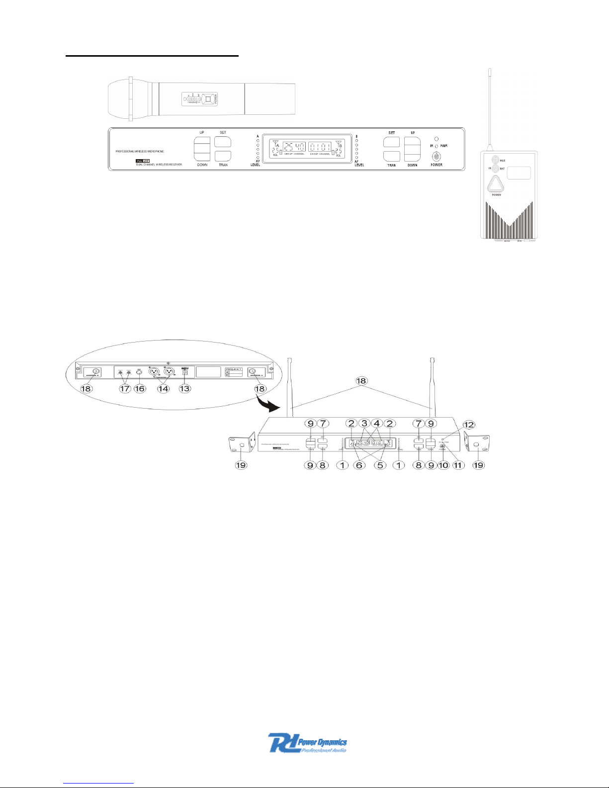
SYSTEM COMPONENTS
Bodypack Transmitter (lavalier mic., headset mic and guitar system)
Handheld microphone
Dual channel receiver
RECEIVER FUNCTIONS/FEATURES
1. Audio level indicator: Indicates the level of the audio signal. Green LED shows normal
operation and red light shows overload of the signal.
2. Antenna Signal indicator: Appears on both sides of the display, the strength depends on
which antenna receives the strongest RF signal.
3. Channel group indication : Shows the preset group (25) - (bandwidth is 25MHz/group).
4. Channel indication: Shows the frequency data of the selected group (40 channels -channel
interval is 25kHz).
5. Battery indicator: Indicates the capacity of the battery in the transmitter.
6. Squelch: Displays SQLdata -100dBm to-50dBm (1-50).
7. SET button: Select Group / ch / SQL.
8. TRAN button: Transmits the data from point 7. to the transmitter by infrared. IR indicator
on the transmitter flashes during data transfer.
9. ▲ and ▼ buttons: Group / Channel / SQLdata selection.
10. Power button: Turns the receiver on / off.
11. IR / PWR Indicator: Displays IR/Power.
12. IR Sensor
Page 5
13. Adaptor input connector (12-18Vdc)
14. XLR out jacks (balanced)
15. Volume control
16. 6.35mm jack output (unbalanced)
17. Squelch: 2 controls channel A / B to improve signal quality and reduce noise. The system
is factory pre-set.
18. TNC antenna connectors (inputs): The connectors also provide 9Vdc to connect an
antenna amplifier.
19. 19 " Rack mounting brackets. The brackets also have a hole where the antennas can be
front-mounted and be connected via extension leads (order number 179.119).
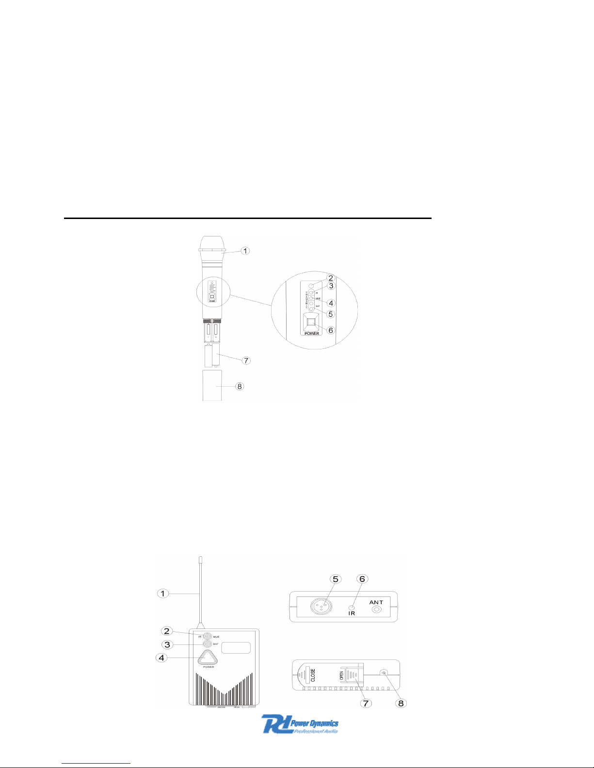
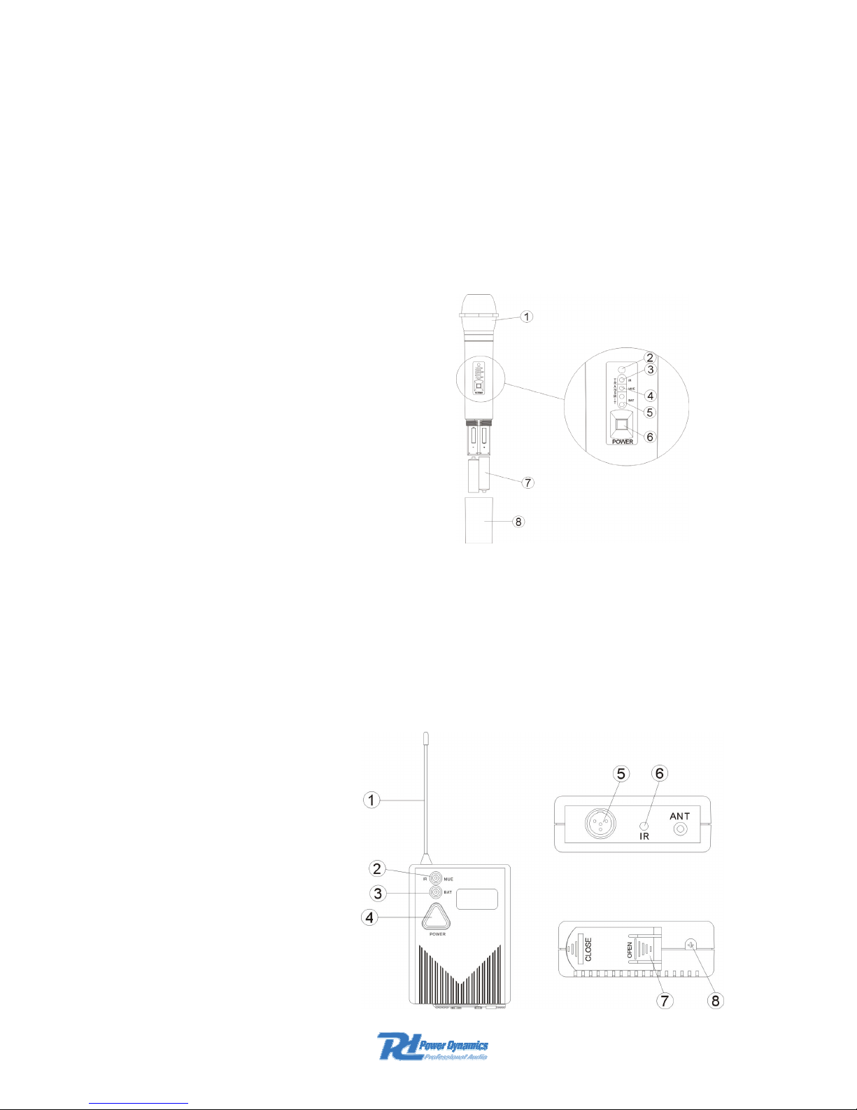
HAND-HELD TRANSMITTER FUNCTIONS/FEATURES
1. Grill : Protects the microphone cartridge and reduces wind noise.
2. IR sensor : Receives data from receiver.
3. IR indicator : Indicates waiting for data.
4. Mute indicator : Indicates mute is set.
5. Battery indicator : Green lightÆ battery is normal. Red light Æ battery must be renewed.
6. Power button
7. Battery 2x AA 1.5V alkaline
8. Battery cover
BODY-PACK TRANSMITTER FUNCTIONS/FEATURES
Page 6
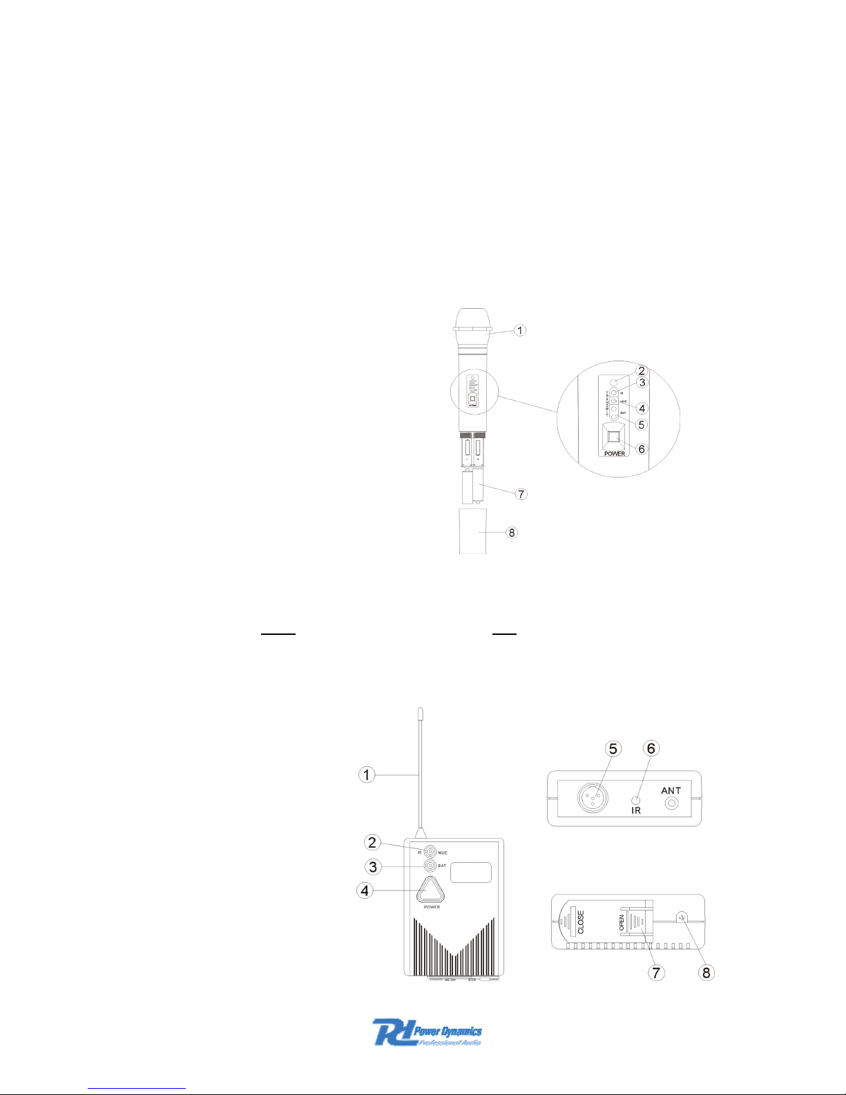
1. Antenna: Attach the flexible antenna to the transmitter
2. IR / Mute indicator: Green light means waiting for a code. Red light indicates mute mode. If the
indicator is off, the system is in normal operation mode.
3. Power battery indication: Red light indicates a low battery power.
4. Power On / Off button.
5. Input Connector : To suit Lavalier mic. / Headband mic. / Guitar - system.
6. IR sensor.
7. Battery cover.
8. Audio Gain to control the audio sensitivity.
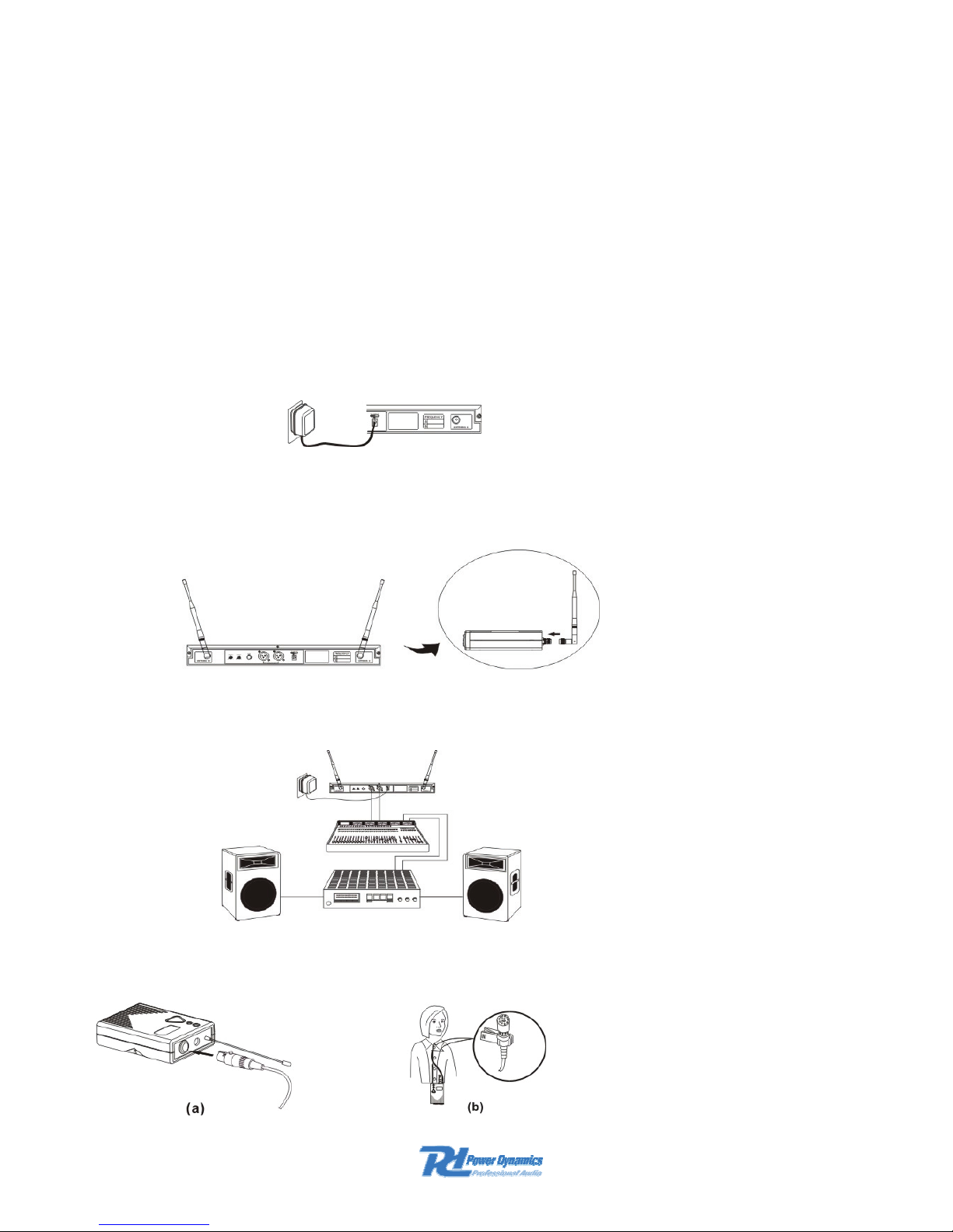
SYSTEM CONNECTIONS
Receiver Power Connection
Connect the AC adaptor into the DC power connector on the back of the receiver. Plug the
adaptor into a mains outlet.
Antenna Connection
Attach the two antennas to the Antenna connectors.
Audio connection
Connect the audio cable from audio output on the receiver to the input on the amplifier micer
equipment.
TRANSMITTER CONNECTIONS
Lavalier microphone
Page 7
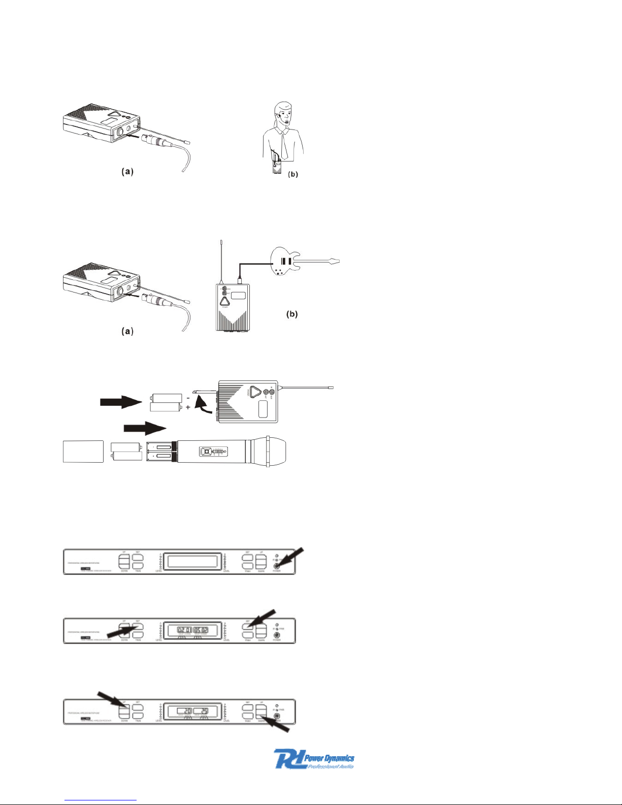
Headset microphone
Guitar system
Battery installation
RECEIVER OPERATION INSTRUCTION
Do not turn on the transmitter before turn on the receiver.
Power up receiver
Channel set up : Press Set button, channel display will flash.
Press ▲ and ▼ buttons. Select a channel as required.
Page 8
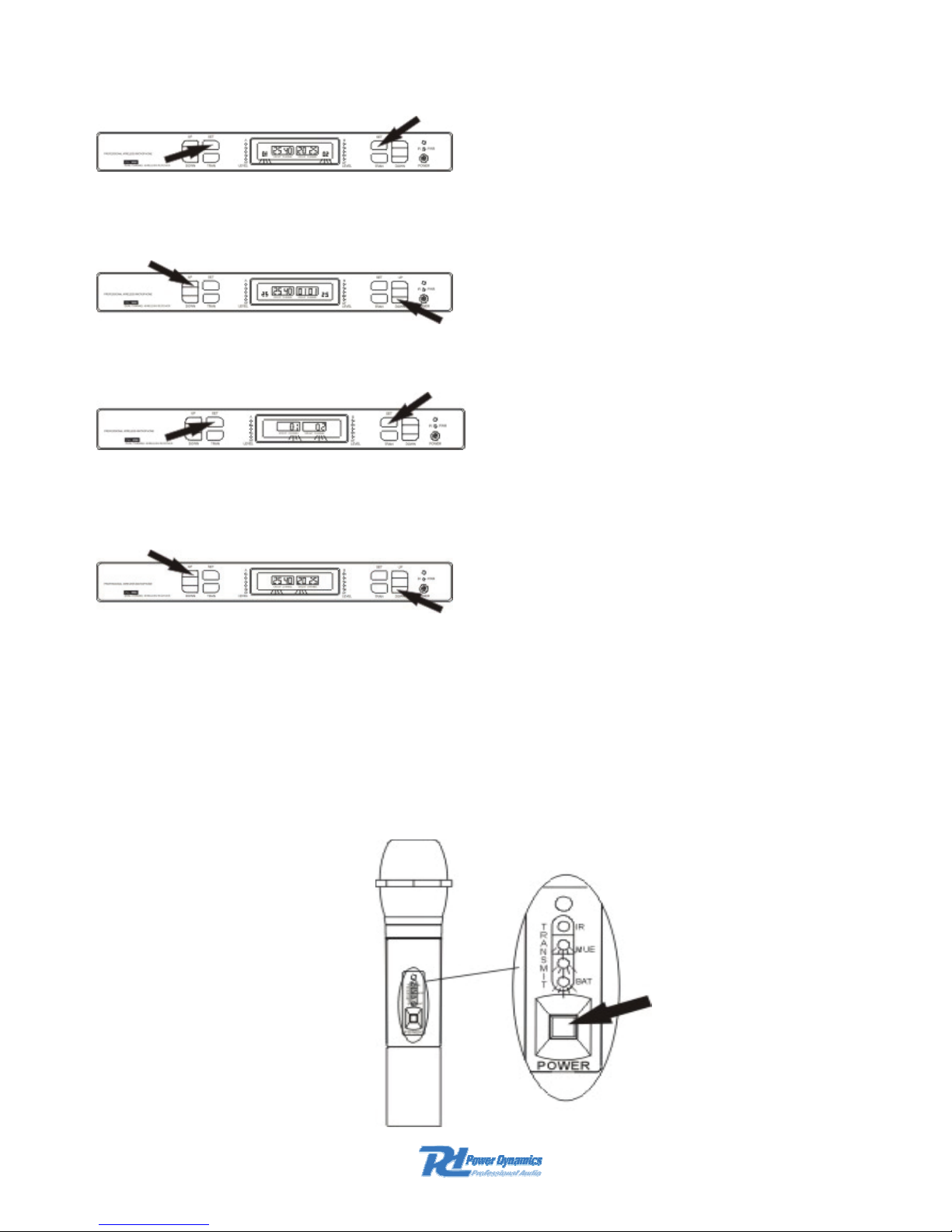
Group set up : Press Set button, group display will flash.
Press ▲ and ▼ buttons. Select a group as required.
SQL installation : Press SET button. The SQL display will flash.
Press ▲ and ▼ buttons. Select a SQL setting as required.
Note : For all Group/Channel/SQL settings, the receiver first processes the data and then
transfers the data to the transmitter by infrared link. Data will be retained until the receiver is
reset.
HAND-HELD TRANSMITTER OPERATION
Don’t turn on the transmitter when the receiver is off. The channel has to be set well too before.
Length press 2a3 seconds the Power button of the transmitter . The IR/MUE/Bat indicator lights,
the transmitter entering adjusting code and transfers the RF signal.
Page 9
If it is needing to adjust a code (adjust channel) , enter the adjusting code mode. After +/- 20
seconds the IR green light black out exiting the adjusting code. The MUE BAT lights, indicating
entering mute. If there is no need for adjusting the code, short press (1 second) the Power button
entering normal operation.
Short press (1 second) the Power button, BAT lights only entering normal operation.
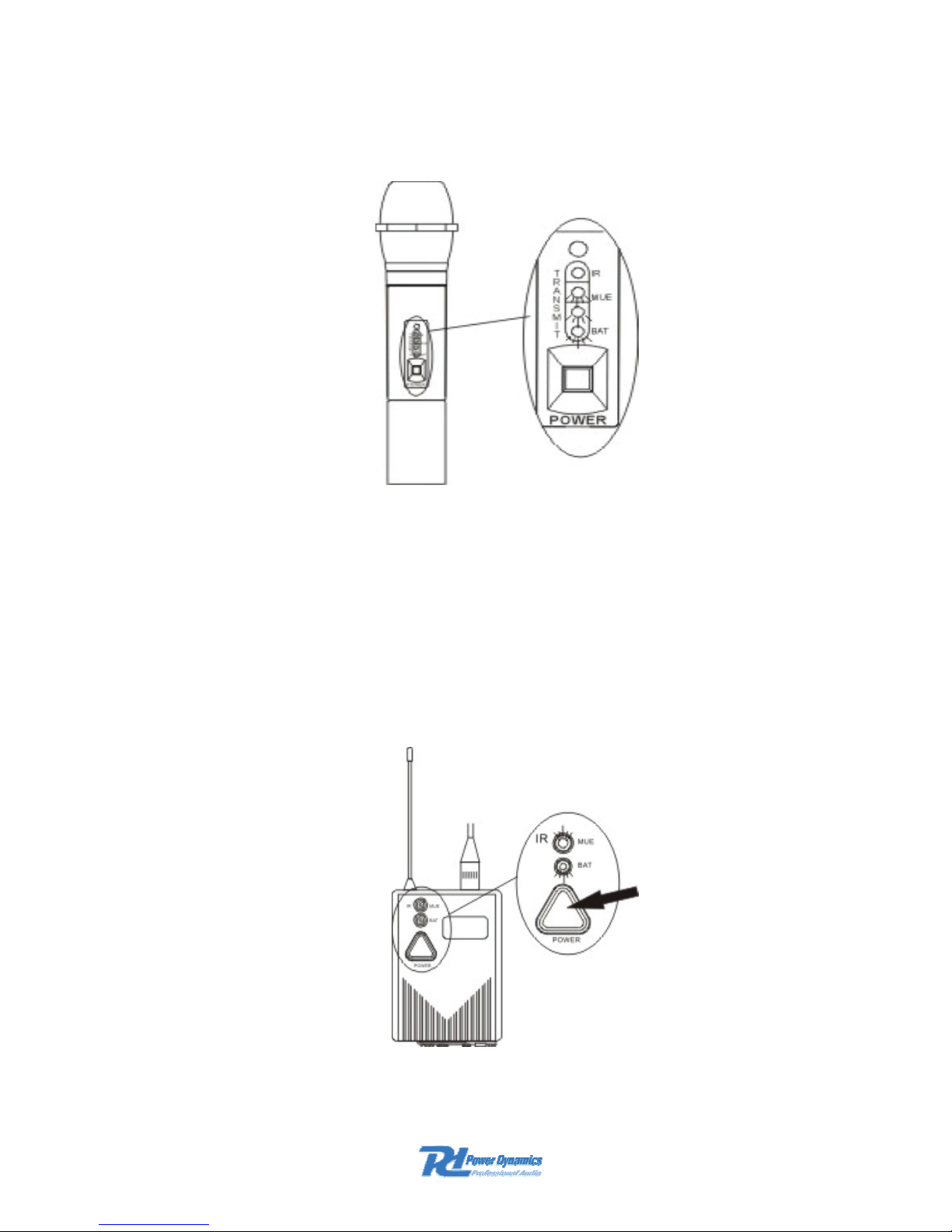
BODY-PACK TRANSMITTER OPERATION
Don’t turn on the transmitter when the receiver is off. The channel has to be set well too before.
Length press 2a3 seconds the Power button of the transmitter . The IR/MUE/Bat indicator lights,
the transmitter entering adjusting code and transfers the RF signal.
IR/MUE is green
Length press Power button
Page 10
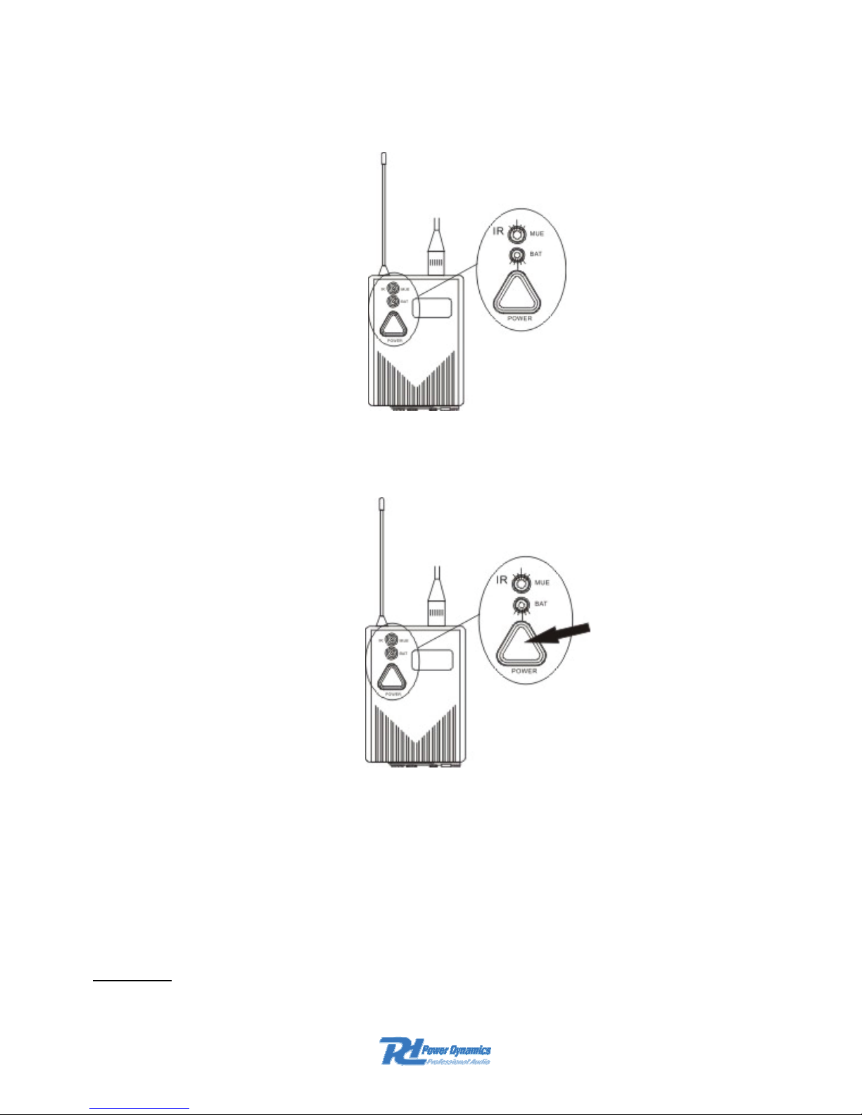
If it is needing to adjust a code (adjust channel) , enter the adjusting code mode. After +/- 20
seconds the IR green light black out exiting the adjusting code. The MUE BAT lights, indicating
entering mute. If there is no need for adjusting the code, short press (1 second) the Power button
entering normal operation.
IR/MUE is red
Short press Power button
Short press (1 second) the Power button, BAT lights only entering normal operation.
Short press Power button
ADJUSTING CODE INSTALLATION
The code can be set only once. The data of a channel is stored forever. The code must be saved
within 20 seconds after turning on the transmitter otherwise the green IR LED turns off and the
transmitter comes into mute mode. Because this system works on two different frequency bands
the code should be twice set for both Channel A and B.
Channel A
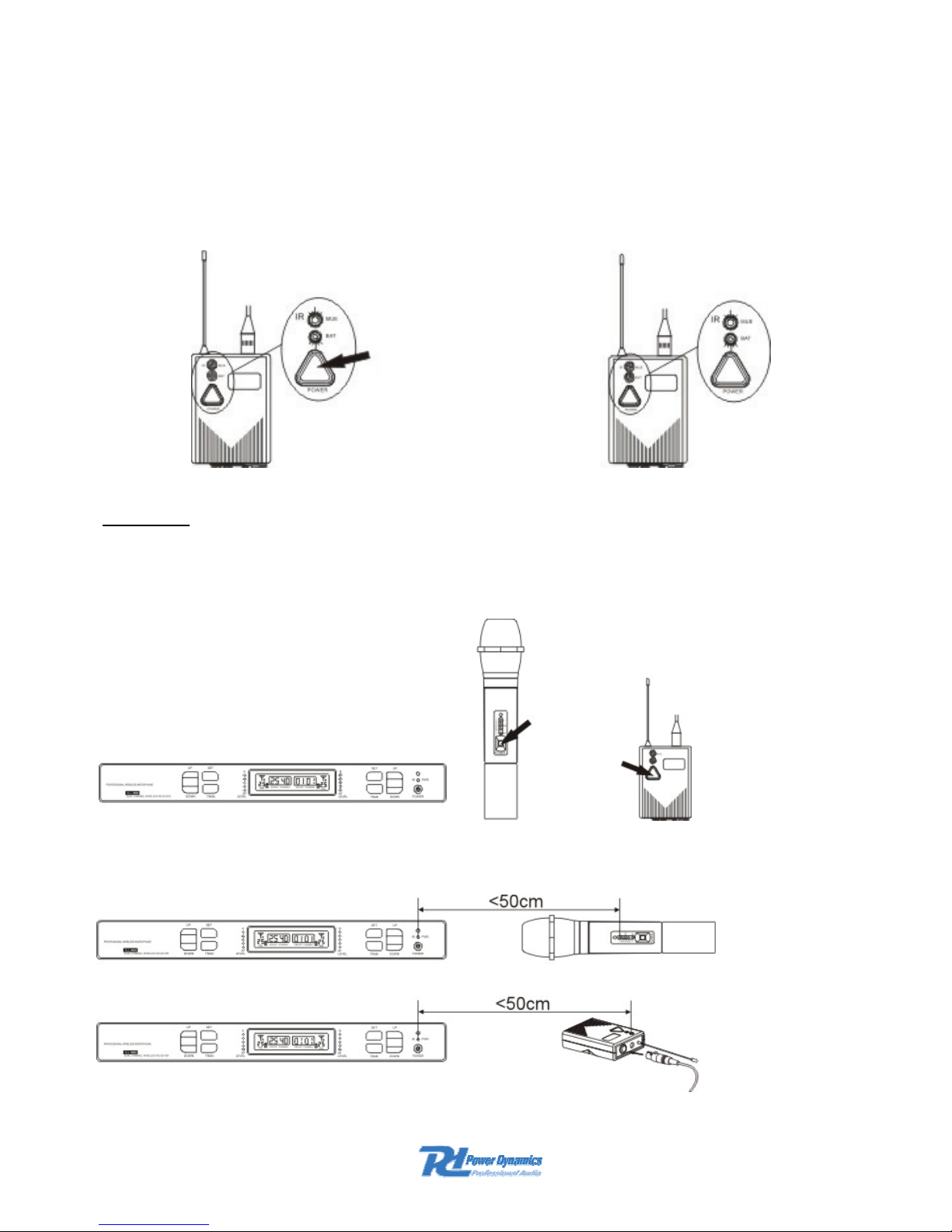
Length press (2a3 seconds) the Power button of the receiver and lenth press then the power
button of the transmitter.
Page 11
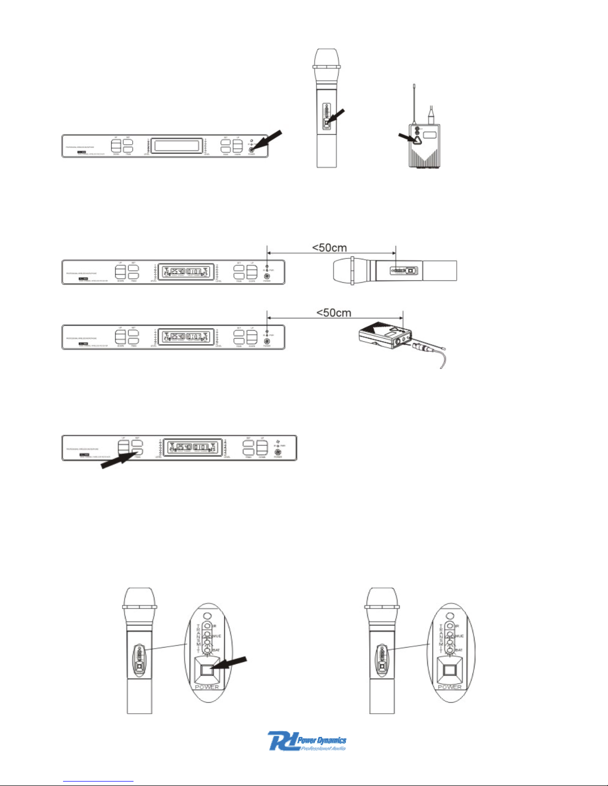
Don’t turn on the transmitter when the receiver is off. The channel has to be set well too before.
The distance between receiver and transmitter is not more than 50cm.
Press TRAN button of the receiver, the IR/PWR light flashes indicating transmitter and receiver
entering adjusting code.
Handheld microphone :
When the transmitter accepts the adjusting code data of the receiver, the system will show the
following:
The IR light will turn off indicating finishing adjusting code and enter MUTE (MUE BAT light) at
the time, pls short press the Power button and enter normal operation. On the contrary if the
system does not finish de adjusting code it needs a re-adjusting.
Page 12
Bodypack transmitter :
When the transmitter accepts the adjusting code data of the receiver, the system will show the
following:
The green IR light changes to red MUE light indicating finishing adjusting code and enter MUTE
(MUE BAT light) at the time, pls short press the Power button and enter normal operation. On the
contrary if the system does not finish de adjusting code it needs a re-adjusting.
Channel B
Because of channel A and B are operating in the identical power system, the receiver need not to
be opened again entering the adjusting procedure. Only the transmitter B need to be opened to
enter the adjusting code.
The distance between receiver and transmitter is not more than 50cm.
Page 13

Press the TRAN button of the receiver, the IR/PWR light flashes indicating the transmitter and
receiver entering adjusting code.
Leaf through the manual to the information regarding “Handheld microphone” and “Bodypack
transmitter” completing adjusting code.
CHECKING THE TRANSMITTER BATTERY POWER
With the receiver and transmitter turned on, after adjust code correctly, short press the Power
button of transmitter and enter normal transmitter mode (BAT lights only). Observe the battery
icon on the display. The number of bars is on the icon. 3 Bars means that the battery is fully
loaded while 1 bar means that the battery is low. If the battery display flashes the battery need to
be renewed.
RACK MOUTING SINGLE RECEIVERS
Position the rack mount brackets over the holes into the sides of the receiver. Secure the
brackets with the supplied screws. Do not overtight the screws. Slide the receiver into the 19”
rack. Secure the brackets to the rack.
Page 14

Specifications
The available frequency spectrum is 790-812MHz. The operating frequency for each country is
depending on local regulations.
The range of this system is about 50-100 meters (maximum) depending on the circumstances.
The frequency range is 25Hz-15kHz 2dB.
2x 1000 selectable UHF channels
PLL synthesizer
Digital tone lock squelch
Dual channel operation
Receiver :
Impedance ................................................................................................................50 Ohm
Nom. Input level .............................................................................................-95 tot -30dBm
Max. Input level.................................................................. +6dBm (-20dBm recommended)
Audio out – XLR (600 Ohm)......................................................................................... 24mV
Audio out – Jack 6.35mm(3kOhm)............................................................................. 360mV
Transmitter :
Modulation FM ........................................................................................................ +/-25kHz
E.r.p. ........................................................................................................................... 10mW
Dynamic range.......................................................................................................... >100dB
RF Sensitivity ........................................................................................................... 105dBm
Image rejection ..................................................................................................80dB typical
Spurious rejection .............................................................................................. 75dB typical
Distortion....................................................................................................................... 0.3%
Power supply :
Transmitters........................................................................................................2 x AA 1.5V
Receiver...................................................................................................12-18Vdc , 500mA
Operating temperature...................................................................................... -20°C - 49°C
Dimensions:
Body-Pack transmitter.................................................................................. 83 x 67 x 25mm
Handheld microphone................................................................................245mm x 50ømm
Receiver................................................................................................... 395 x 195 x 45mm
This appliance should not be put into the domestic garbage at the end of its useful life, but must be disposed
of at a central point for recycling of electric and electronic domestic appliances. This symbol on appliance, instruction
manual and packaging puts your attention to this important issue. The materials used in this appliance can be
recycled. By recycling used domestic appliances you contribute an important push to the protection of our
environment. Ask your local authorities for information regarding the point of recollection.
At the moment only for use in NL-D-B ; Wait for Digital Dividend Band
Do not attempt to make any repairs yourself. This would invalid your warranty. Do not make any changes to the unit. This
would also invalid your warranty. The warranty is not applicable in case of accidents or damages caused by
inappropriate use or disrespect of the warnings contained in this manual. Power Dynamics cannot be held responsible
for personal injuries caused by a disrespect of the safety recommendations and warnings. This is also applicable to all
damages in whatever form.
0678
Page 15

NL
Hartelijk dank voor de aanschaf van deze Power Dynamics draadloze microfoonkit. Lees de
gebruiksaanwijzing aandachtig door alvorens het apparaat in bedrijf te stellen.
WAARSCHUWING
-
Lees altijd eerst de gebruiksaanwijzing voordat u een apparaat gaat gebruiken.
- Bewaar de handleiding zodat elke gebruiker hem eerst kan doorlezen.
- Bewaar de verpakking zodat u, indien het apparaat defect is, deze in de originele
verpakking kunt opsturen om beschadigingen te voorkomen.
- Apparaat alleen binnenshuis en in niet vochtige ruimtes gebruiken.
- Toestel niet in de buurt van warmtebronnen en of in direct zonlicht gebruiken.
- Zorg ervoor dat er geen kleine objecten of vloeistof in het toestel kunnen binnendringen.
- Toestel alleen reinigen met een licht vochtige stofvrije doek, geen reinigingsmiddelen of
oplosmiddelen gebruiken!
- Het toestel bevat buiten de in de gebruiksaanwijzing genoemde onderdelen geen
onderdelen die door de gebruiker vervangen of gerepareerd kunnen worden.
- Open nooit zelf het apparaat, laat reparaties over aan gekwalificeerd personeel.
- Verwijder of plaats de netvoeding nooit met natte handen respectievelijk uit en in het
stopcontact.
- Voordat het apparaat gerepareerd of onderhouden wordt, dient deze eerst losgekoppeld te
worden van de netspanning.
- Bij hergebruik kan condensatiewater gevormd worden; laat het apparaat eerst op
omgevingstemperatuur komen.
- Het apparaat buiten bereik van kinderen houden.
- Indien het apparaat dusdanig beschadigd is dat inwendige (onder)delen zichtbaar zijn,
mag de stekker NOOIT in het stopcontact worden geplaatst én het apparaat NOOIT
worden ingeschakeld. Neem in dit geval contact op met uw leverancier.
- Bij onweer altijd de adapter uit het stopcontact halen, zo ook wanneer het apparaat voor
langere tijd niet wordt gebruikt.
- Door het gebruik van dit product kan de werking van onvoldoende afgeschermde of
gevoelige elektronische apparatuur worden verstoord. Deze storing kan tot ongelukken of
beschadiging van uw apparatuur leiden. Controleer daarom voor het inschakelen van dit
apparaat of er geen apparatuur in de nabije omgeving is die gevoelig kan zijn voor
storingen.
Page 16

Systeem componenten
Body pack zender ( bestaande uit dasspeld mic., headset mic., of gitaaraansluiting.)
Handmicrofoon
Dual kanaals ontvanger
Ontvanger : Bediening
1. Audio niveau indicatie : Geeft het niveau van het audiosignaal weer. Groene indicatie
betekent normale weergave terwijl rode indicatie een overbelasting van het signaal
weergeeft.
2. Antennesignaal indicatie : Verschijnt aan beide zijden van de display, de sterkte is
afhankelijk van welke antenne het sterkste signaal ontvangt.
3. Kanaal-groep indicatie : Geeft de voorgeprogrammeerde groep (25) weer (bandbreedte is
25MHz/groep).
4. Kanaal indicatie : Geeft de frequentiedata weer van de geselecteerde groep ( 40 kanalenkanaal interval is 25kHz).
5. Batterij indicatie : Geeft de capaciteit van de batterij in de zender weer.
6. Squelch : Geeft SQLdata weer van -100dBm tot -50dBm (1-50).
7. SET toets : Kies Groep/kanaal/SQL en toets SET.
8. TRAN toets : Zendt de data uit punt 7. naar de zender via IR. IR-indicatie op de zender
knippert tijdens de overdracht.
9. ▲ en ▼ toetsen: Hiermee zijn de Groep/Kanaal/SQLdata te selecteren.
10. Aan/Uit toets : Hiermee wordt de ontvanger aan/uitgezet.
11. IR/PWR indicatie : Geeft IR functie weer.
12. IR sensor
Page 17
13. Adapter aansluiting (12-18Vdc)
14. XLR-uit aansluitingen (gebalanceerd)
15. Volumeregelaar
16. Jack 6.35mm uitgang (ongebalanceerd)
17. Squelch : 2 regelaars kanaal A/B om de signaalkwaliteit te verbeteren en de ruis te
onderdrukken. De regeling is door de fabrikant gepre-set.
18. Antenne TNC connectoren (ingangen) : De antennes zijn hierop aan te sluiten. Tevens zijn
de connectoren voorzien van een 9Vdc uitgang om eventueel een antenne-versterker op
aan te sluiten.
19. 19” Rack bevestigingsbeugels. De beugels zijn tevens voorzien van een gat waar de
antennes op aangesloten kunnen worden waardoor ze middels verlengkabeltjes (179.119
bestel nummer) aan de voorkant komen te zitten ivm rackmontage.
Handmicrofoon functies
1. Beschermrooster : Voor bescherming van het element.
2. IR ontvanger
3. IR indicatie voor data.
4. Mute indicatie : Brandt wanneer op Mute is gedrukt.
5. Batterij indicatie : Groen geeft normale situatie weer, Rood geeft weer dat de batterij
vervangen moet worden.
6. Aan/Uit toets
7. Batterij : 2x AA 1.5V alkaline
8. Batterijkap
Bodypack zender
functies
Page 18

1. Antenne : Plaats de flexibele antenne op de zender
2. IR/Mute indicatie : Groen betekent wachtend op een code. Rood geeft Mute mode weer. Als
de indicator uit is, is het systeem normaal in bedrijf.
3. Power batterij indicatie : Rood geeft een lage batterijspanning weer.
4. Power Aan/Uit toets.
5. Ingangsconnector voor Dasspeld/Hoofdband/Gitaar – aansluiting.
6. IR sensor.
7. Batterijdeksel.
8. Audio regelaar voor het regelen van de audio gevoeligheid.
Systeem aansluitingen
1. Netaansluiting : Sluit de adapter aan op het lichtnet (230Vac/50Hz) en plaats de
voedingsplug in de ontvanger op de achterzijde.
2. Antenne aansluiting : Sluit de 2 antennes aan op de connectoren.
3. Audio aansluiting : Sluit de audio-apparatuur aan op de ontvanger.
Zender aansluitingen
1. Dasspeld-microfoon aansluiting.
Page 19

2. Hoofdband microfoon aansluiting.
3. Gitaar aansluiting.
4. Plaatsen van de batterij.
Bediening van de ontvanger ( het kiezen van kanalen)
1. Zet eerst de ontvanger aan en dan pas de zender.
2. Kanaal Set up : Toets de SET toets, de Kanaal-display knippert.
Toets ▲ of ▼ om een kanaal te selecteren.
Page 20

1. Als de code moet worden ingesteld (kanaal afstellen) ga dan naar de code mode (zie
verder op in de handleiding). Na +/- 20 seconden gaat het IR groene led uit, ga dan uit de
mode. De MUE/BAT Led’s gaan aan die aangeven dat de microfoon in Mute-mode komt.
Wanneer de code niet behoeft te worden ingesteld, druk dan 1 seconde op de Power-toets
en de microfoon is bedrijfsklaar.
2. Wanneer 1 seconde op Power wordt gedrukt gaat het BAT-Ledje aan om in in-bedrijf
mode te komen.
Bodypack bediening
Zet eerst de ontvanger aan. Zet pas de microfoon aan als het gewenste kanaal is geset
1. Houd de Power-toets 2 a 3 seconden vast, de code wordt door de ontvanger opgeslagen,
IR/MUE/BAT Led’s gaan branden en het hoogfrequent signaal van de microfoon kan
worden verzonden.
IR/MUE is groen
Power toets vasthouden
Page 21

2. Als de code moet worden ingesteld (kanaal afstellen) ga dan naar de code mode (zie
verder op in de handleiding). Na +/- 20 seconden gaat het IR groene led uit, ga dan uit de
mode. De MUE/BAT Led’s gaan aan die aangeven dat de bodypack in Mute-mode komt.
Wanneer de code niet behoeft te worden ingesteld, druk dan 1 seconde op de Power-toets
en de bodypack is bedrijfsklaar.
IR/MUE is rood
Power toets 1 sec.
vasthouden
3. Wanneer 1 seconde op Power wordt gedrukt gaat het BAT-Ledje aan om in in-bedrijf
mode te komen.
Power toets 1 sec.
vasthouden
Code mode
Het instellen van de code kan maar één keer. De data van een kanaal wordt voor altijd
opgeslagen. De code moet binnen 20 seconden na het inschakelen van de zender worden
opgeslagen anders gaat het groene IR Ledje uit en komt de zender in Mute-mode. Omdat dit
systeem op 2 verschillende frequentiebanden werkt moet de code twee maal worden ingesteld
voor zowel kanaal A als B.
Kanaal A
Druk 2 a 3 seconden op de Power-toets van de ontvanger en daarna 2 a 3 seconden op de
Power-toets van de zender.
Page 22

Power-toets 2 a 3 seconden vasthouden. Eerst de ontvanger inschakelen.
Zorg ervoor dat de zender binnen 50cm van de ontvanger gehouden moet worden.
Druk op de TRAN-toets van de ontvanger, de IR/PWR indicatie knippert ten teken dat beiden in
de code-mode komen.
Handmicrofoon :
Wanneer de zender de ontvangen code accepteert van de ontvanger zal het volgende te zien
zijn:
De IR indicatie op de zender gaat uit ten teken dat de synchronisatie is voltooid en de zender
komt in Mute-mode (MUE/BAT brandt). Druk nu 1 seconde op Power en de zender komt in
bedrijfsmode. Gebeurt dit niet dan is de synchronisatie mislukt en moet deze opnieuw worden
gedaan.
Page 23

Bodypack zender :
Wanneer de zender de ontvangen code accepteert van de ontvanger zal het volgende te zien
zijn:
Wanneer de groene IR led uitgaat en de rode MUE led gaat aan is de synchronisatie voltooid en
komt de zender in Mute-mode (MUE/BAT brandt). Druk nu 1 seconde op Power en de zender
komt in bedrijfsmode. Gebeurt dit niet dan is de synchronisatie mislukt en moet deze opnieuw
worden gedaan.
Kanaal B
Op de Power-toets van de ontvanger drukken hoeft niet meer omdat zowel Kanaal A als B
dezelfde voeding hebben. Druk nu 2 a 3 seconden op de Power-toets van de andere zender (B)
om de code instelling hiervoor door te voeren.
Zorg ervoor dat de zender binnen 50cm van de ontvanger gehouden moet worden.
Page 24

Druk op de TRAN-toets van de ontvanger, de IR/PWR indicatie knippert ten teken dat beiden in
de code-mode komen.
Blader terug naar de informatie over “Handmicrofoon” en “Bodypack zender” voor het
voltooien van de code-mode instelling.
Batterij capaciteit controleren
Als de ontvanger en de zender ingeschakeld zijn, nadat de code instelling is voltooid, kan 1
seconde op de power-toets van de zender gedrukt worden (BAT Led brandt). Kijk naar de bars
op de LED-bar van de display. 3 bars geeft aan dat de batterij vol is en bij1 bar is de batterij leeg.
Als de batterij-indicatie knippert is de batterij vermoedelijk stuk.
Rackmontage
Positioneer de hoekstukken en zet deze vast met de meegeleverde schroeven. Draai deze niet te
vast. Laat de ontvanger in het rack glijden en monteer deze met de meegeleverde schroeven.
Page 25
Specificaties
Het beschikbare frequentiegebied is 790-812MHz. De werkfrequentie is per land afhankelijk van
de daar geldende richtlijnen.
Het bereik van dit systeem is ongeveer 50-100 meter (optimaal) afhankelijk van de
omstandigheden.
Het frequentiebereik is 25Hz-15kHz 2dB.
2x 1000 te kiezen UHF kanalen.
PLL synthesizer
Digitaal tone-lock squelch.
Ontvanger :
Impedantie ................................................................................................................50 Ohm
Nom. Ingangsniveau ...................................................................................... -95 tot -30dBm
Max. Ingangsniveau................................................................+6dBm (-20dBm aanbevolen)
Audio uit – XLR (600 Ohm).......................................................................................... 24mV
Audio uit – Jack 6.35mm(3kOhm).............................................................................. 360mV
Zender :
Modulatie FM .......................................................................................................... +/-25kHz
Uitgangsvermogen...................................................................................................... 10mW
Dynamisch bereik ..................................................................................................... >100dB
Gevoeligheid ............................................................................................................ 105dBm
Beeld rejectie ..................................................................................................... 80dB typical
Spurious rejectie ................................................................................................ 75dB typical
Vervorming.................................................................................................................... 0.3%
Voeding :
Zenders...............................................................................................................2 x AA 1.5V
Ontvanger ................................................................................................ 12-18Vdc , 500mA
Bedrijfstemperatuur............................................................................................. -20°C-49°C
Afmetingen:
Body-Pack.................................................................................................... 83 x 67 x 25mm
Handmicrofoon...........................................................................................245mm x 50ømm
Ontvanger ................................................................................................ 395 x 195 x 45mm
Afgedankte artikelen !!
Raadpleeg eventueel www.nvmp.nl en/of www.vrom.nl
v.w.b. het afdanken van elektronische apparaten in het kader van de
WEEE-regeling. Vele artikelen kunnen worden gerecycled, gooi ze daarom niet bij het huisvuil maar lever ze in bij een
gemeentelijk depot of uw dealer. Lever ook afgedankte batterijen in bij uw gemeentelijk depot of bij de dealer, zie
www.stibat.nl
.
Voer zelf geen reparaties uit aan het apparaat; in elk geval vervalt de totale garantie. Ook mag het apparaat niet eigenmachtig worden
gemodificeerd, ook in dit geval vervalt de totale garantie. Ook vervalt de garantie bij ongevallen en beschadigingen in elke vorm t.g.v.
onoordeelkundig gebruik en het niet in acht nemen van de waarschuwingen in het algemeen en gestelde in deze gebruiksaanwijzing.
Tevens aanvaardt Power Dynamics geen enkele aansprakelijkheid in geval van persoonlijke ongelukken als gevolg van het niet
naleven van veiligheidsinstructies en waarschuwingen. Dit geldt ook voor gevolgschade in welke vorm dan ook.
0678
Momenteel te gebruiken in NL-B-D; wacht op Digitale Dividend Band
Page 26

D
Herzlichen Glückwunsch zum Kauf dieser drahtlosen Funkmikrofonanlage von Power Dynamics.
Bitte lesen Sie diese Anleitung sorgfältig vor der Inbetriebnahme durch.
SICHERHEITSVORSCHRIFTEN:
- Vor Inbetriebnahme die Anleitung durchlesen.
- Für spätere Bezugnahme aufbewahren.
- Verpackung aufbewahren, so dass jederzeit ein sicherer Transport gewährleistet ist.
- Nur für Innengebrauch in trockenen Räumen.
- Vor Hitze schützen.
- Keine Flüssigkeiten oder Gegenstände durch die Belüftungsschlitze dringen lassen.
- Das Gerät nur mit einem leicht angefeuchteten, fusselfreien Tuch abwischen. Keine
Reinigungs- oder Lösungsmittel benutzen.
- Niemals das Gehäuse öffnen; Reparaturen nur von einem Fachmann ausführen lassen.
- Beim Abziehen des Steckers immer am Stecker ziehen, niemals an der Netzschnur.
- Bei Unwetter, sowie Nichtgebrauch das Netzgerät aus der Steckdose ziehen.
- Nach längerem Nichtgebrauch kann sich Kondenswasser im Gehäuse gebildet haben.
Lassen Sie das Gerät erst auf Raumtemperatur kommen.
- Wenn das Gerät sichtbar beschädigt ist, darf es NICHT an eine Steckdose angeschlossen
und NICHT eingeschaltet werden. Benachrichtigen sie in diesem Fall Power Dynamics
- Vor Kindern schützen.
- Stecker niemals mit nassen Händen anfassen.
- Vor Instandhaltungs- und Reparaturarbeiten erst den Stecker abziehen.
- Dieses Gerät kann bei empfindlichen oder ungenügend abgeschirmten Geräten Störungen
verursachen, die zu Pannen führen können. Bevor Sie dieses Gerät benutzen,
vergewissern Sie sich, dass sich in der näheren Umgebung keine Geräte befinden, die
gestört werden könnten.
Page 27

System Komponenten
Bodypack Sender (mit Krawatten- und Kopf- Mikrofon und Anschluß für Gitarre)
Handmikrofon
Dual-Kanal Empfänger
Empfänger : Bedienung
1. Audio-Pegel-Anzeige: Zeigt den Pegel des Audiosignals. Ein grünes Signal zeigt eine normale
Wiedergabe während ein rotes Signal eine Überbelastung des Signals zeigt.
2. Antenne-Signal Anzeige: Erscheint auf beiden Seiten des Displays, abhängig von : Welche
Antenne empfängt das stärkste Signal.
3. Kanalgruppe Anzeige : Zeigt Ihnen die vorprogrammierten Gruppen (25)-(Bandbreite ist
25MHz/gruppe).
4. Kanal Anzeige : Zeigt die Frequenzdaten der ausgewählte Gruppe (40 Kanäle- Kanal Intervall
ist 25kHz).
5. Batterie Anzeige: Zeigt die Kapazität der Batterie im Sender.
6. Squelch: Zeigt SQLDaten von -100dBm bis-50dBm (1-50).
7. SET-Taste: Wählen Sie Gruppe / Kanal / SQL und drücken Sie die SET-Taste.
8. TRAN-Taste: Überträgt (Infrarot) die Daten aus Punkt 7. an den Sender. IR-Indikator auf dem
Sender blinkt während der Datenübertragung.
9. Tasten ▲ und ▼: Hiermit können Sie die Gruppe / Kanal / SQL Daten auswählen.
10. Power-Taste: Schaltet der Empfänger ein / aus.
11. IR / PWR-Anzeige: Zeigt IR-Funktion.
12. IR-Sensor
Page 28
13. Adapterkabel (12-18VDC)
14. XLR-Ausgangsbuchsen (symmetrisch)
15. Lautstärkeregelung
16. 6,35-Klinke-Ausgang (unsymmetrisch)
17. Squelch: 2 Regler Kanal A/B um die Qualität des Signals zu verbessern und Geräusche zu
reduzieren. Das System ist werkseitig voreingestellt.
18. TNC Antenne Anschlüsse (Eingänge): Die Antennen sind hier an zu schließen. Die
Anschlüsse sind auch ausgestattet mit einem 9Vdc Ausgang für Speisung eines
Antennenverstärkers.
19. 19 "Rack Halterungen. Die Halterungen haben auch ein Loch wo die Antennen
angeschlossen werden, so dass sie über Verlängerungskabel (Bestellnummer 179.119) auf
der Vorderseite zu montieren sind (für Rack-Montage).
Handmikrofon
1. Schutzgitter: Zum Schutz des Elements.
2. IR-Empfänger
3. IR-Daten Anzeige.
4. Mute-Anzeige: Leuchtet, wenn die Mute-Taste gedrückt wird.
5. Batterie Anzeige: Grün zeigt die normale Situation, Rot bedeutet dass die Batterie
ausgetauscht werden muss.
6. Ein / Aus Taste
7. Batterie: 2x AA 1,5 V Alkaline
8. Batteriefachabdeckung
Bodypack Sender
Page 29

1. Antenne: Die flexible Antenne auf den Sender montieren
2. IR / Mute-Anzeige: Grün bedeutet, das System wartet auf einem Code. Rot bedeutet
Mute-anzeige (Stummschaltung). Wenn die Anzeige nicht leuchtet, ist das System im
normalen Betrieb.
3. Batterie-Power Anzeige: Rot weist auf eine niedrige Batteriespannung.
4. Power Ein / Aus-Taste.
5. Eingangsverbinder für Krawatten- / Kopf- / Gitarre - Anschluss.
6. IR-Sensor.
7. Batterieabdeckel.
8. Audio-Empfindlichkeits Regler.
System Anschlüsse
Schließen Sie das Netzteil an das Stromnetz (230VAC/50Hz) und schließen Sie die
Klinkenbüchse an auf der Rückseite.
Antennen-Anschluss: Die beide Antennen mit den Einbaubüchsen verbinden.
Audio-Anschluss: Die Audio-Geräte mit dem Empfänger verbinden.
Sender Anschlüsse
Krawattenmikrofon Anschluß
Page 30

Kopfmicrofon Anschluß
Gitarre Anschluß
Batterien einlegen
Empfänger Bedienung ( Wahl der Kanäle)
Schalten Sie den Empfänger ein bevor der Sender betrieben wird.
Kanal Set-up : Drücken Sie die SET-Taste, die Kanal-Anzeige blinkt.
Drücke ▲ oder ▼ um ein Kanal zu wählen.
Page 31

Gruppe Set-up : Drücken Sie die SET-Taste, die Gruppe-Anzeige blinkt.
Drücke ▲ oder ▼ um eine Gruppe zu wählen.
Squelch Set-up : Drücken Sie die SET-Taste, die SQL-Anzeige blinkt.
Drücke ▲ oder ▼ um die gewünschte SQL zu wählen. (Empfohlen wird zwischen 15 und 20 )
Hinweis: Für die oben genannten Einstellungen gilt daß der Empfänger zuerst alle Daten
verarbeitet und dann auf das Mikrofon überträgt via Infrarot. Die Daten werden gespeichert bis
ein Reset an dem Empfänger durchgeführt wird.
Handmikrofon Bedienung
Schalten Sie den Empfänger ein. Schalte nur das Mikrofon ein wenn das gewünschte Kanal
festgelegt ist
Drücken Sie den Netzschalter 2 oder 3 Sekunden, der Empfänger speichert den Code, IR / MUE
/ BAT LED's leuchten und das hochfrequente Signal vom Mikrofon wird übertragen.
Page 32

Wenn der Code festgelegt werden sollte (Kanal-Tuning) gehen Sie zum Code-Modus (siehe
weiter im Handbuch). Nach + / - 20 Sekunden geht die grüne IR-LED aus, dann verlassen Sie
den Modus. Die MUE / BAT LED’s leuchten auf und zeigen an dass das Mikrofon im
Stummzustand (Mute) ist. Wenn der Code nicht festgelegt werden muss, dann 1 Sekunde die
Power-Taste drücken und das Mikrofon ist in Betrieb.
Wenn 1 Sekunde die Power-Taste gedrückt wird leuchtet die BAT LED auf um in Betriebmodus
zu kommen.
Bodypack Sender Bedienung
Schalten Sie den Empfänger ein, dann das gewünschte Kanal festlegen und danach den Sender
einschalten.
Drücken Sie die Power-Taste 2 oder 3 Sekunden, der Empfänger speichert den Code, IR / MUE /
BAT LED's leuchten und das hochfrequente Signal wird vom Mikrofon übertragen.
IR/MUE LED ist grün
Power-Taste 3 Sekunden
drücken
Page 33

Wenn der Code festgelegt werden sollte (Kanal-Tuning) gehen Sie zum Code-Modus (siehe
weiter im Handbuch). Nach + / - 20 Sekunden geht die grüne IR-LED aus, dann verlassen Sie
den Modus. Die MUE / BAT LED’s leuchten auf und zeigen an dass das Mikrofon im
Stummzustand (Mute) ist. Wenn der Code nicht festgelegt werden muss, dann 1 Sekunde die
Power-Taste drücken und das Mikrofon ist in Betrieb.
IR/MUE ist rot
Power-Taste 1 Sekunde
drücken
Wenn 1 Sekunde die Power-Taste gedrückt wird leuchtet die BAT LED auf um in Betriebmodus
zu kommen.
Power-Taste 1 Sekunde
drücken
Code Modus
Der Code kann nur einmal festgelegt werden. Die Daten eines Kanals werden für immer
gespeichert. Der Code muss innerhalb von 20 Sekunden nach dem Einschalten des Senders
gespeichert werden ansonsten leuchtet die grüne IR-LED nicht mehr und kommt der Sender in
Mute-Modus. Da dieses System arbeitet auf zwei verschiedenen Frequenzbändern sollte
zweimal den Code für Kanal A und B festgelegt werden.
Kanal A
Drücken Sie 2 oder 3 Sekunden die Power-Taste am Empfänger und dann 2 oder 3 Sekunden
die Power-Taste am Sender.
Page 34

Die Power-Taste 2 oder3 seconden festhalten. Zuerst der Empfänger einschalten.
Vergewissern Sie sich daß sich der Sender innerhalb von 50cm des Empfängers befindet.
Drücken Sie die TRAN-Taste des Empfängers, die IR/PWR Anzeige blinkt, Empfänger und
Sender kommen jetzt in Code-Modus.
Handmikrofon :
Wenn der Sender den empfangenen Code des Empfängers akzeptiert zeigt sich folgendes :
Der IR-Indikator am Sender leuchtet nicht mehr. Die Synchronisation ist jetzt abgeschlossen, der
Sender kommt im Ruhezustand (MUE / BAT leuchtet). Drücken Sie 1 Sekunde die Power-Taste
und der Sender ist im Betriebsmodus, ansonsten ist die Synchronisation nicht abgeschlossen
und muss die Festlegung noch einmal versucht werden.
Page 35

Bodypack Sender
Wenn der Sender den empfangenen Code des Empfängers akzeptiert zeigt sich folgendes :
Wennn der grüne IR-Indikator am Sender nicht mehr leuchtet und der rote MUE- LED leuchtet
auf, ist die Synchronisation jetzt abgeschlossen und kommt der Sender im Ruhezustand (MUE /
BAT leuchtet). Drücken Sie 1 Sekunde die Power-Taste und der Sender ist im Betriebsmodus,
ansonsten ist die Synchronisation nicht abgeschlossen und muss die Festlegung noch einmal
versucht werden.
Kanal B
Die Power-Taste des Empfängers drücken brauchen Sie nicht mehr weil das Netzteil die
Speisung versorgt für Kanal A und B. Drücken Sie jetzt 2 bis 3 Sekunden die Power-Taste des BKanals um die Codefestlegung durch zu führen.
Vergewissern Sie sich daß sich der Sender innerhalb von 50cm des Empfängers befindet.
Page 36

Drücken Sie die TRAN-Taste des Empfängers, die IR/PWR Anzeige blinkt, Empfänger und
Sender kommen jetzt in Code-Modus.
Blättern Sie zurück zu den Informationen über "Handmikrofon" und "Body Pack Sender", um den
Code modus festzulegen.
Akku Kapazität überprüfen
Wenn der Empfänger und Sender eingeschaltet sind, nachdem die Codefestlegung
abgeschlossen ist, 1 Sekunde die Power-Taste am Sender drücken (BAT LED leuchtet).
Schauen Sie sich die Bars auf der LED-Bar an. 3 Bars weisen darauf hin, dass den Akku voll und
bei 1 Bar leer ist und wenn die Batterie-Anzeige blinkt, den Akku wahrscheinlich defekt ist.
Rackmontage
Positionieren und montieren Sie die zwei 19” Metallwinkel mit den mitgelieferten Schrauben.
Page 37

Technische Daten
Das zur Verfügung stehende Frequenzspektrum ist 790-812MHz (für jedes Land je nach den
örtlichen Vorschriften).
Der Bereich dieses Systems ist etwa 50-100 Meter (maximal) je nach den Umständen.
Der Frequenzbereich ist 25Hz-15kHz 2dB.
Empfänger :
Impedanz ..................................................................................................................50 Ohm
Nom. Eingangspegel..................................................................................... -95 bis -30dBm
Max. Eingangspegel .................................................................+6dBm (-20dBm empfohlen)
Audio Ausgang – XLR (600 Ohm)................................................................................ 24mV
Audio Ausgang – Jack 6.35mm(3kOhm).................................................................... 360mV
Sender :
Modulation FM ........................................................................................................ +/-25kHz
Ausgangsleistung........................................................................................................ 10mW
Dynamischer Bereich................................................................................................ >100dB
Empfindlichkeit......................................................................................................... 105dBm
Bild rejection ...................................................................................................... 80dB typical
Spurious rejection .............................................................................................. 75dB typical
THD............................................................................................................................... 0.3%
Speisung :
Sender ................................................................................................ 2 x AA 1.5V Batterien
Empfänger ...............................................................................................12-18Vdc , 500mA
Betriebstemperatur ........................................................................................-20°C bis 49°C
Abmessungen:
Body-Pack Sender ....................................................................................... 83 x 67 x 25mm
Handmicrofon.............................................................................................245mm x 50ømm
Empfänger ............................................................................................... 395 x 195 x 45mm
Dieses Produkt darf am Ende seiner Lebensdauer nicht über den normalen Haushaltsabfall entsorgt werden,
sondern muss an einem sammelpunkt für das Recycling abgegeben werden. Die Werkstoffe sind gemäß
ihrer Kennzeichnung wieder verwertbar. Hiermit leisten Sie einen wichtigen Beitrag zum Schutze unserer
Umwelt.
Lithiumbatterien und Akkupacks sollten nur im entladenen Zustand in die Altbatteriesammelgefäße bei Handel und
bei öffentlich-rechtlichen Entsorgungsträgern gegeben werden. Bei nicht vollständig entladenen Batterien Vorsorge
gegen Kurzschlüß treffen durch Isolieren der Pole mit Klebestreifen.
Derzeit nur für gebrauch in NL-B-D ; Warte auf „Digital Dividend Band“
Reparieren Sie das Gerät niemals selbst und nehmen Sie niemals eigenmächtig Veränderungen am Gerät vor. Sie verlieren
dadurch den Garantieanspruch.
Der Garantieanspruch verfällt ebenfalls bei Unfällen und Schäden in jeglicher Form, die durch unsachgemäßen Gebrauch und
Nichtbeachtung der Warnungen und Sicherheitshinweise in dieser Anleitung entstanden sind.
Power Dynamics ist in keinem Fall verantwortlich für persönliche Schäden in Folge von Nichtbeachtung der
Sicherheitsvorschriften und Warnungen. Dies gilt auch für Folgeschäden jeglicher Form.
0678
Page 38

Page 39
Page 40

Specifications and design are subject to change without prior notice..
www.tronios.com
Copyright © 2010 by TRONIOS the Netherlands
 Loading...