

Page 1

PPoowweerr oovveerr EEtthheerrnneett
PPoowweerr VViieeww PPrroo
e
UUsseerr GGuuiidde
Page 2

RReemmoottee WWeebb MMaannaaggeerrss
Notice
The information contained herein is believed to be accurate and
reliable at the time of printing. However, due to ongoing product
improvements and revisions, PowerDsine cannot accept
responsibility for inadvertent errors, inaccuracies, subsequent
changes or omissions of printed material.
PowerDsine Ltd. reserves the right to make changes to products
and to their specifications as described in this document, at any
time, without prior notice. No rights to any PowerDsine Ltd.
Intellectual property are licensed to any third party, either directly,
by implication or by any other method.
©
2006 PowerDsine Ltd.
All rights reserved.
This document is subject to change without notice.
Acknowledgements
All other products or trademarks are property of their respective
owners.
The product described by this manual is a licensed product of
PowerDsine.
Abbreviations and Terminology
Abbreviations are spelled out in full when first used. Only industry-
standard terms are used throughout this manual.
Note: Covered under U.S patent S/N 6,473,608. Other Patents
pending
PPoowweerrDDssiinnee
PPoowweerr oovveerr EEtthheerrnneett SSoolluuttiioonnss
2
Page 3

RReemmoottee WWeebb MMaannaaggeerrss
1
1
AAbboouutt tthhiiss GGuuiiddee.....................................................................
1.1 Objectives .....................................................................................6
1.2 Audience.......................................................................................6
1.3 Organization .................................................................................7
1.4 Conventions..................................................................................8
1.5 Related Documentation ................................................................8
1.6 Abbreviations ................................................................................8
2
2
IInnttrroodduucciinngg tthhee PPoowweerr VViieeww PPrroo.........................................
2.1 Overview.......................................................................................9
2.2 Features........................................................................................9
2.3 System Capabilities ................................................................... 10
2.3.1 Configuration options..................................................................10
2.4 Security & User Authentication.................................................. 11
2.4.1 Web Configuration...................................................................... 11
2.4.2 SNMP .........................................................................................11
2.4.3 Telnet Configuration ...................................................................12
3.1 Installation.................................................................................. 13
3.1.1 Configuration Options................................................................. 13
3.2 System Requirements ............................................................... 14
3.3 Hardware Setup......................................................................... 15
3.4 Installation Procedure ................................................................ 16
3.4.1 Web Browsing ............................................................................16
3.4.2 Telnet Browsing..........................................................................16
3.4.3 RS232 Configuration using Hyper Terminal Application............16
3.4.4 Configuring the System via the HyperTerminal.......................... 19
3.4.5 Using the View Menu..................................................................20
3.4.6 Using the Configuration & Maintenance Menu........................... 20
3.4.7 Using the Ping Remote Host Menu ............................................ 22
3.5 TFTP Server Configuration........................................................ 23
4
4
GGUUII DDeessccrriippttiioonn.......................................................................
4.1 Overview.................................................................................... 24
4.2 Opening Screen......................................................................... 24
4.3 View Screen............................................................................... 25
4.3.1 View Status Screen .................................................................... 26
4.3.2 View – Network & Security Configuration Screen ...................... 33
4.3.3 View - Product Information .........................................................38
4.4 System Configuration Screen.................................................... 39
4.4.1 System Configuration Network Screen ......................................39
Table of Contents
.......................................................................................66
.....................................................................99
...................................................................................2244
PPoowweerrDDssiinnee
PPoowweerr oovveerr EEtthheerrnneett SSoolluuttiioonnss
3
Page 4

RReemmoottee WWeebb MMaannaaggeerrss
4.4.2 System Configuration SNMP...................................................... 43
4.4.3 System Configuration SNMPv3..................................................47
4.4.4 System Configuration Security ................................................... 50
4.4.5 System Configuration Product Parameters................................ 53
4.4.6 System Configuration Maintenance ...........................................55
4.5 Port Configuration Screen ......................................................... 57
4.5.1 Port Configuration Enable/Disable .............................................58
4.5.2 Port Configuration Detailed ........................................................ 60
5
5
SSNNMMPP MMoonniittoorriinngg aanndd CCoonnffiigguurraattiioonn GGUUII...........................
5.1 General ...................................................................................... 63
5.2 SNMP MIB's............................................................................... 63
5.3 RFC3621 PoE MIB .................................................................... 64
5.4 Private MIB ................................................................................ 65
6
6
OOppeerraattiioonn...................................................................................
6.1 General ...................................................................................... 66
6.2 Logging in .................................................................................. 67
6.3 Viewing System Status.............................................................. 68
6.4 Viewing Network & Security Configuration Status..................... 69
6.5 Viewing Product Information...................................................... 70
6.6 Configuring System - Network................................................... 70
6.7 Configuring System SNMP........................................................ 73
6.8 Configuring System SNMPv3 .................................................... 74
6.9 Configuring System Security ..................................................... 75
6.9.1 Protecting View by Password.....................................................77
6.9.2 Modifying Remote Access.......................................................... 77
6.10 Configuring Product Parameters ............................................... 80
6.11 Configuring System Maintenance.............................................. 81
6.12 Configuring the Ports ................................................................. 82
6.13 Configuring Additional Port Settings.......................................... 84
6.13.1 Specific Ports Settings................................................................85
6.13.2 All Ports Settings ........................................................................ 85
7
7
TTrroouubblleesshhoooottiinngg.......................................................................
7.1 General ...................................................................................... 86
8
8
SSooffttwwaarree UUppddaattee.......................................................................
8.1 Architecture................................................................................ 90
8.2 Software Upgrade...................................................................... 91
8.2.1 General.......................................................................................91
8.2.2 Upgrade Process........................................................................92
8.2.3 Software update from version 1.xx to 2.xx ................................. 94
.........................................................................................6666
...................................................................................8866
.................................................................................9900
...............................................6633
PPoowweerrDDssiinnee
PPoowweerr oovveerr EEtthheerrnneett SSoolluuttiioonnss
4
Page 5

RReemmoottee WWeebb MMaannaaggeerrss
List of Figures
Figure 2-1: Management Deployment............................................................. 10
Figure 2-2: Connecting the PoE Unit............................................................... 15
Figure 4-1: Opening Screen ............................................................................ 25
Figure 4-2: View Menu .................................................................................... 25
Figure 4-3: View Status Screen....................................................................... 26
Figure 4-4: Ports Status Panel ........................................................................ 27
Figure 4-5: View - Product Information Screen ............................................... 38
Figure 4-6: System Configuration Screen ....................................................... 39
Figure 4-7: System Configuration Network Screen......................................... 40
Figure 4-8: System Configuration SNMPv3 Screen........................................ 47
Figure 4-9: System Configuration Security Screen ......................................... 50
Figure 4-10: System Configuration Product Parameters Screen .................... 53
Figure 4-11: System Configuration Maintenance Screen ............................... 55
Figure 4-12: Port Configuration Screen........................................................... 57
Figure 4-13: Port Configuration Enable/Disable Screen ................................. 58
Figure 4-14: Port Configuration Detailed Screen (60xxG, 65xx family) .......... 60
Figure 4-15: Port Configuration Detailed Screen (80xx Midspan family) ........ 61
Figure 5-1: MIB Tree Structure........................................................................ 64
Figure 5-2: MIB’s Management Funtionalities................................................. 65
Figure 6-1: Network Management Tool........................................................... 66
Figure 8-1: System Software Architecture....................................................... 90
List of Tables
Table 1-1: Conventions Used .......................................................................... 8
Table 4-1: Main Status Indications .................................................................. 27
Table 4-2: 60xxG Gigabit Midspan Port Status Indications............................. 28
Table 7-1: Troubleshooting Steps ................................................................... 86
PPoowweerrDDssiinnee
PPoowweerr oovveerr EEtthheerrnneett SSoolluuttiioonnss
5
Page 6

RReemmoottee WWeebb MMaannaaggeerrss
11
AAbboouutt tthhiiss GGuuiiddee
1.1 Objectives
This User Guide introduces PowerDsine’s Power View Pro Remote
Web Managers used for managing PowerDsine’s Power over
Ethernet (PoE) product line of Midspan devices including:
♦ PD – 6506/AC/M – 6 ports 10/100Mbit Midspan
♦ PD – 6512/AC/M – 12 ports 10/100Mbit Midspan
♦ PD – 6524/AC/M – 24 ports 10/100Mbit Midspan
♦ PD – 6524/AC/M/F – 24 ports 10/100Mbit full power Midspan
♦ PD – 6548/AC/M – 48 ports 10/100Mbit Midspan
♦ PD – 8006/AC/M – 6 ports 10/100Mbit High Power Midspan
♦ PD – 8012/AC/M – 12 ports 10/100Mbit High Power Midspan
♦ PD - 6006G/AC/M – 6 ports 1Gigabit Midspan
♦ PD - 6012G/AC/M – 12 ports 1Gigabit Midspan
♦ PD - 6024G/AC/M – 24 ports 1Gigabit Midspan
1.2 Audience
This Guide is intended for network administrators, supervisors and
installation technicians who have a background in:
PPoowweerrDDssiinnee
♦ Basic concepts and terminology of networking
♦ Network topology
♦ Protocols
♦ Microsoft Windows environment
PPoowweerr oovveerr EEtthheerrnneett SSoolluuttiioonnss
6
Page 7

RReemmoottee WWeebb MMaannaaggeerrss
1.3 Organization
This Guide is divided into several Sections, as follows:
Section 1 - Defines the overall concepts used in this Guide,
conventions used and associated documentation.
Section 2 - Describes the Power View Pro features and capabilities.
Section 3 – Provides a complete system installation procedure.
Section 4 - Provides the GUI detailed description.
Section 5 - Explains how to use the PowerView Pro GUI.
Section 6 – Provides a troubleshooting guide
Section 7 – Explains the process for upgrading Midspan software.
PPoowweerrDDssiinnee
PPoowweerr oovveerr EEtthheerrnneett SSoolluuttiioonnss
7
Page 8

RReemmoottee WWeebb MMaannaaggeerrss
s
yp
yer
1.4 Conventions
The various conventions used in defining commands and examples
are given in Table 1-1.
Table 1-1: Conventions Used
CONVENTION DEFINITION
bold Keywords & commands
italic
screen Displayed Information
Bold screen Information to be entered
Notes Helpful information
1.5 Related Documentation
For additional information, refer to the following documentation:
♦ Power over Ethernet PowerDsine PD-60XX (AC and DC
version), User Manual (06-6800-056).
♦ IEEE Standard 802.3af, DTE Power via MDI.
1.6 Abbreviations
Represents a GUI item
PPoowweerrDDssiinnee
PoE
NTP
DES
MD5
MDI
MIB
PD
SNMP
SSL
FTP
TFTP
Power over Ethernet
Network Time Protocol
Data Encr
Message Digest 5
Multiple-Document Interface
Management Information Base
Powered Device
Simple Network Management Protocol
Secure Sockets La
File Transfer Protocol
Trivial File Transfer Protocol
tion Standard
PPoowweerr oovveerr EEtthheerrnneett SSoolluuttiioonnss
8
Page 9

RReemmoottee WWeebb MMaannaaggeerrss
22 IInnttrroodduucciinngg tthhee PPoowweerr VViieeww PPrroo
2.1 Overview
PowerDsine’s Power View Pro is a management system, utilized for
complete monitoring and control of PowerDsine’s Power over
Ethernet (PoE) Midspans, via a remote network management
station. The system provides direct on-line power supervision,
configuration, monitoring and diagnostics of PowerDsine products
via their SNMP managers.
NOTE:
The principle of operation is similar for all Midspan models
described in this manual
2.2 Features
The manager provides a number of unique features for PoE
Midspan management as follows:
♦ HTTP - Web based for remote management of Power over
Ethernet device
♦ SSL - Secured WEB based configuration
♦ Configuration using graphical representations of remote device
♦ SNMPv2c/v1/v3
♦ RFC3621 Power over Ethernet (PoE) SNMP MIBs
♦ Private MIB extension to RFC3621 PoE MIB
♦ Telnet – Remote terminal over Ethernet Network
♦ Real time monitoring with visual status
♦ System status display
♦ SysLog Server - Log events to remote SysLog Server
PPoowweerrDDssiinnee
PPoowweerr oovveerr EEtthheerrnneett SSoolluuttiioonnss
9
Page 10
RReemmoottee WWeebb MMaannaaggeerrss
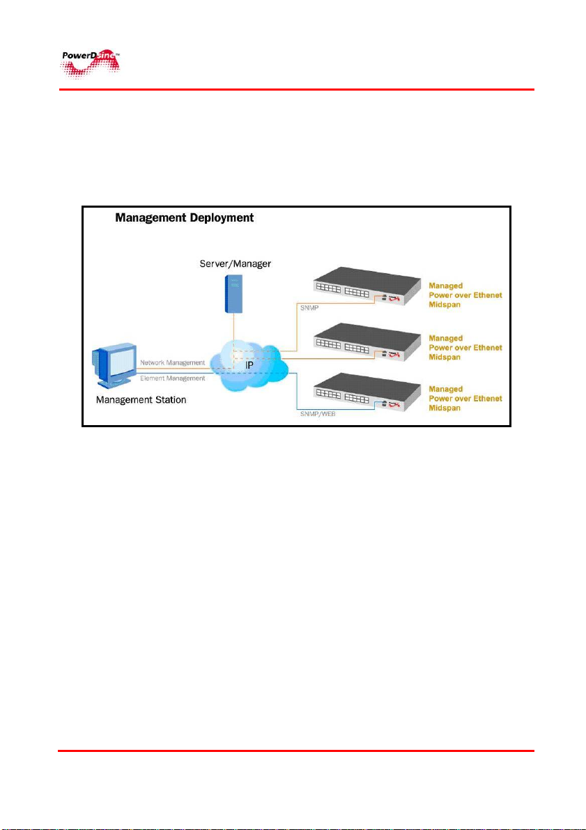
2.3 System Capabilities
The manager can be accessed from any computer by WEB browser
such as an Internt Explorer/Netscape, SNMP management station,
Telnet, or RS232 Terminal. The Power View Pro allows monitoring
and controlling of over Etehrnet IP networks as shown in Figure 2-1:
Figure 2-1: Management Deployment
2.3.1 Configuration options
• Web based – by utilizing a WEB browser
• SNMPv1/2c/3 – by utilizing an SNMP management application
on a remote computer
• Telnet – via the RJ45 Etehrnet port by using Telent application
on a remote computer
• Serial communication port – by using Terminal emulation
software such as Microsoft Windows Hyper Terminal, or any
similar software.
• Serial communication rate must be set to 38400, no hardware
flow control and cross cable should be used (pin2 crossed with
pin3).
PPoowweerrDDssiinnee
PPoowweerr oovveerr EEtthheerrnneett SSoolluuttiioonnss
10
Page 11

RReemmoottee WWeebb MMaannaaggeerrss
NOTE:
The unit is shipped with default IP of 192.168.0.50. Make sure that
a computer Network card is configured to the same IP network.
• Telnet and WEB configuration are password protected.
• Serial communication configuration should be used in order to
define the unit’s IP address, upload / download unit
configuration, restore unit configuration to factory default, or
perform software updates. Any other configuration should be
carried out via the WEB browser.
2.4 Security & User Authentication
2.4.1 Web Configuration
Web configuration can be protected by user by password. Two user
& password protection levels are avilable as follow:
• View username & password – a remote user has access
to Web pages that provide various information, but has no
permission to perform any modifications.
• Configuration username & password - a remote user
(usually administrator) has full authority to modify any unit’s
parameter.
2.4.2 SNMP
• SNMP v1/v2 - community string is utilized for authentication
• SNMP v3 – Network Management Protocol Version-3
PPoowweerrDDssiinnee
Get/Set/Trap authentication.
(SNMPv3) is an standards-based protocol, utilized for
network management. It provides secure access to devices
by a combination of authenticating and encrypting packets
over the network.
PPoowweerr oovveerr EEtthheerrnneett SSoolluuttiioonnss
11
Page 12

RReemmoottee WWeebb MMaannaaggeerrss
2.4.3 Telnet Configuration
Since Telnet provide access to IP configuration, software updates
and data bases upload/download functions, it is always password
protected (regardless of Web view & configure password selection
option).
WEB and Telnet utilize the same passwords (Telnet utilizes Web
browser password even if the Web password function is disabled).
NOTE:
The PPoowweerr VViieeww PPrroo
Protection:
Configuration password protection
WEB/Telnet:
View (usually user) : user name =”user”, password =”password”
Configure (usually administrator): user name =”admin”, password =
”password”.
SNMP v3:
Guest (usually remote SNMP manager) : user name =”public”
View User (usually user) : user name =”view”, authentication
password (MD5) = ”password”, : privacy password (DES)=
”password”,
Admin User (usually administrator) : user name =”admin”,
authentication password (MD5) = ”password”, : privacy password
(DES)= ”password”,
is provided with the following factory defaults:
PPoowweerrDDssiinnee
PPoowweerr oovveerr EEtthheerrnneett SSoolluuttiioonnss
12
Page 13

RReemmoottee WWeebb MMaannaaggeerrss
33
3.1 Installation
3.1.1 Configuration Options
The following configuration options are available:
Via an RJ-45 network connector utilizing a Web browser (IP
192.168.0.50).
Via an RJ-45 network connector utilizing the Telnet protocol
(IP 192.168.0.50).
Via an RS-232 Serial communication port (for PD-6548
please use the speacial cable which was provided with the
unit), utilizing an RS-232 connector ( 38400, HW flow
control off)
IInnssttaallllaattiioonn
NOTE:
This section describes the configuration procedure via the CLI
commands. Configuration of system parameters Via the Web
browser is further detailed in Paragraph 6.6 on page 70.
PPoowweerrDDssiinnee
PPoowweerr oovveerr EEtthheerrnneett SSoolluuttiioonnss
13
Page 14

RReemmoottee WWeebb MMaannaaggeerrss
3.2 System Requirements
The following hardware/software items are required in order to
configure and operate the Power over Ethernet (PoE) Midspan.
♦ Computer Environment
PC Ethernet Network card configured to the following
parameters:
IP : 192.168.0.40,
IP Mask:255.255.255.0
• Operating system: Any Host with WEB browser
• Recommended OS & Web browsers:
√ Win2000/XP running Microsoft Internet explorer
Ver-6 or higher
√ Win2000/XP running Netscape 7 or higher
√ Access to a local network and Internet
• Ethernet cable.
• Telnet application (already provided by Windows/Linux)
• Serial Communication
√ Serial ports: COM1 or COM2 are active and
available
• Null-modem RS232 crossed cable(for PD-6548 please
use the special provided cable)
PPoowweerrDDssiinnee
♦ Administrative Requirements
• The Midspan is shipped with default IP 192.168.0.50.
Before connecting the Midspan to you network, please
make sure no other device is using the same IP
address.
PPoowweerr oovveerr EEtthheerrnneett SSoolluuttiioonnss
14
Page 15
RReemmoottee WWeebb MMaannaaggeerrss
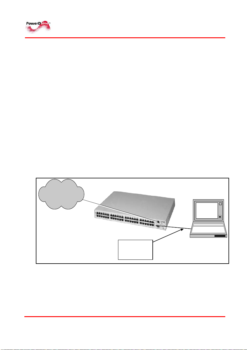
3.3 Hardware Setup
Perform the following steps (see Figure 2-2):
1 Connect an AC power cable to the PoE unit and verify that
all LEDs illuminate once (self test).
2 For configuration through the Serial port, connect the
crossed null-modem cable between the management station
COM port and the PoE RS-232 port.
3 For configuration through the Network, connect a network
cable between the PoE unit front panel’s RJ45 connector
(use Ethernet Hub/Switch or cross cable for straight
connection).
4 Verify that the
Link
LED is green.
5 If any problem is encountered during setup, refer to Chapter.
7, Troubleshooting”:
AC
LED on the front panel is lit and that the
PPoowweerrDDssiinnee
LAN
PoE U nit
To configure
Network Interface
parameters
Figure 2-2: Connecting the PoE Unit
PPoowweerr oovveerr EEtthheerrnneett SSoolluuttiioonnss
15
CROSS E D
NULL
MODEM
CABLE
Mana gement
Station
Page 16

RReemmoottee WWeebb MMaannaaggeerrss
3.4 Installation Procedure
3.4.1 Web Browsing
Open Web browser and type 192.168.0.50 in the address field.
3.4.2 Telnet Browsing
• Go to start -> Run
• Type the command cmd
• In the window type the command, telnet 192.168.0.50
• Type the Username & password
NOTE:
Use Web browser to view System Configuration->Security WEB
page and make sure that the Telnet checkbox is checked
(selected) - see page 48.
3.4.3 RS232 Configuration using Hyper Terminal Application
For WIN 2000 and WIN XP users:
Go to Run (Start> Run).
6
PPoowweerrDDssiinnee
7 Type “cmd”. A DOS type window opens;
click OK.
8 Type the “ipconfig” and then click Enter.
1 Note computer IP, mask and default gateway.
2 Click
Start >Programs >Accessories
Communications
>
>
HyperTerminal
; A dialog
box appears.
PPoowweerr oovveerr EEtthheerrnneett SSoolluuttiioonnss
16
Page 17
RReemmoottee WWeebb MMaannaaggeerrss
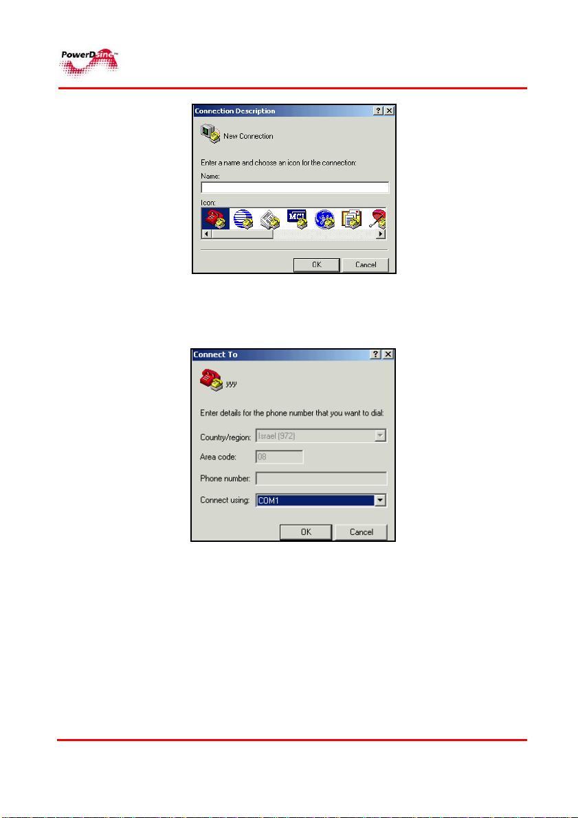
3 Enter your name or organization name in the
and then click
OK; Connect To
window appears.
Name
text field
4 Select the desired communication port to be connected to
the PoE unit and then click OK. A dialog window appears.
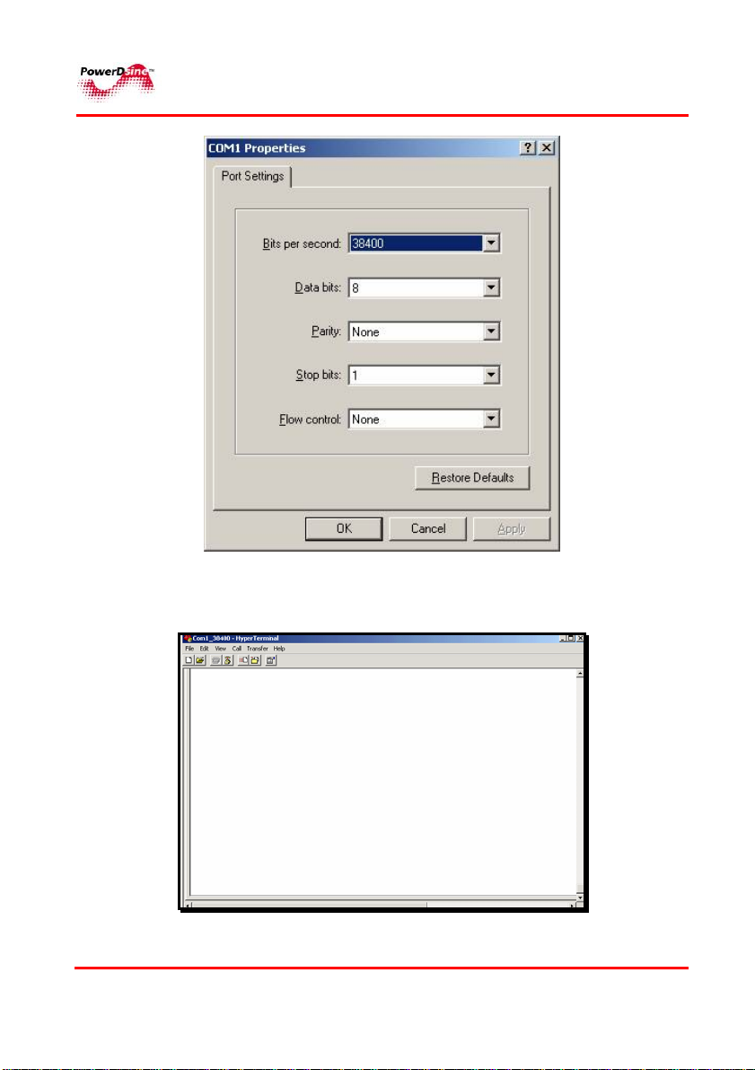
5 Select the following parameters and then click OK:
Bits per second: 38400
Data bits: 8
Parity: None
Stop bits: 1
Flow control: None
PPoowweerrDDssiinnee
PPoowweerr oovveerr EEtthheerrnneett SSoolluuttiioonnss
17
Page 18
RReemmoottee WWeebb MMaannaaggeerrss
PPoowweerrDDssiinnee
9 The HyperTerminal screen appears;
PPoowweerr oovveerr EEtthheerrnneett SSoolluuttiioonnss
18
Page 19

RReemmoottee WWeebb MMaannaaggeerrss
3.4.4 Configuring the System via the HyperTerminal
NOTE:
There is no password protection while using the RS232 serial
communication port. Password protection is only applicable for
Telnet or WEB access.
Perform the following steps:
1 Click the ESC or space key: the main menu
appears:
Main Menu
---------------------------
1. View Menu – view unit IP, software version and release date.
2. Configuration & Maintenance Menu - Configure unit IP,
upload/download configuration & software update
3. Ping Remote Host – determine whether a particular IP system on a
network is functional. Used for diagnosing IP network or router
failures.
E. Exit to debug information screen – enables on going debug
information to be reported by the Terminal.
PPoowweerrDDssiinnee
PPoowweerr oovveerr EEtthheerrnneett SSoolluuttiioonnss
19
Page 20

RReemmoottee WWeebb MMaannaaggeerrss
3.4.5 Using the View Menu
1 Select the
View Menu
option;
View Menu
appears;
View Menu
-----------------------------
1. View Network Parameters – such as IP Address, Subnet Mask,
Default Gateway and MAC Address.
NOTE:
While DHCP is in use, DHCP server IP appears as well.
2. View Application & Boot Software Version – allows viewing of
application and boot version number and creation date.
3. View system up time – displays how many days, hours, minutes &
seconds the unit has been operational.
3.4.6 Using the Configuration & Maintenance Menu
PPoowweerrDDssiinnee
1 Select the
Main Menu
Configuration & Maintenance Menu
; the following menu appears;
PPoowweerr oovveerr EEtthheerrnneett SSoolluuttiioonnss
20
from the
Page 21

RReemmoottee WWeebb MMaannaaggeerrss
Configuration & Maintenance Menu
------------------------------------------------
1. Set Static IP/DHCP – allows the user to set, save & activate new
network parameters.
2. Download Configuration File to Unit –downloading configuration
file from a remote Host named nms.db, using TFTP application
(Host must run TFTP server application prior to using this option see Para. 3.5).
NOTE:
Upon successful downloading, only the manager module will reset
itself without effecting active powered PD devices.
3. Upload Configuration from Unit to File – the unit uploads its
Internal configuration file named nms_out.db to the Host, utilizing
TFTP application (Host must run TFTP server application prior to
using this option - see Para. 3.5).
4. Software Update Menu - allows the user to update unit
software/firmware
NOTE:
Host must run TFTP server application and appropriate software
update package should be available to the user.
PPoowweerrDDssiinnee
PPoowweerr oovveerr EEtthheerrnneett SSoolluuttiioonnss
21
Page 22

RReemmoottee WWeebb MMaannaaggeerrss
5. Restore Username&Password to Factory Default – restores
only view/configure user name & password to default values (only
the manager module will reset itself without effecting active powered PD
devices.
6. Restore the Unit to Factory Default - restores most of the unit
configuration parameters to factory default values. Please note that
in order to allow the remote user to continue and configure the unit
from a remote location, unit IP will remain the same (
manager module will reset itself without effecting active powered PD
devices.
7. Reset Manager Module – O
without effecting active powered PD devices
8. Reset Unit – performs reset of the the entire unit, which will cause
all powered PD devices to be turned off for a several seconds, and
re powered.
ESC - Return to Previous Menu
3.4.7 Using the Ping Remote Host Menu
The Ping Remote Host Menu is utilized to test the TCP/IP configuration by
using the ping command; the user enters the remote IP address.
The ping command then uses the ICMP echo request and echo reply
packets to determine whether a particular IP system on a network is
functional. Ping is useful for diagnosing IP network or router failures.
).
only the
).
nly the manager module will reset itself
.
PPoowweerrDDssiinnee
PPoowweerr oovveerr EEtthheerrnneett SSoolluuttiioonnss
22
Page 23
RReemmoottee WWeebb MMaannaaggeerrss
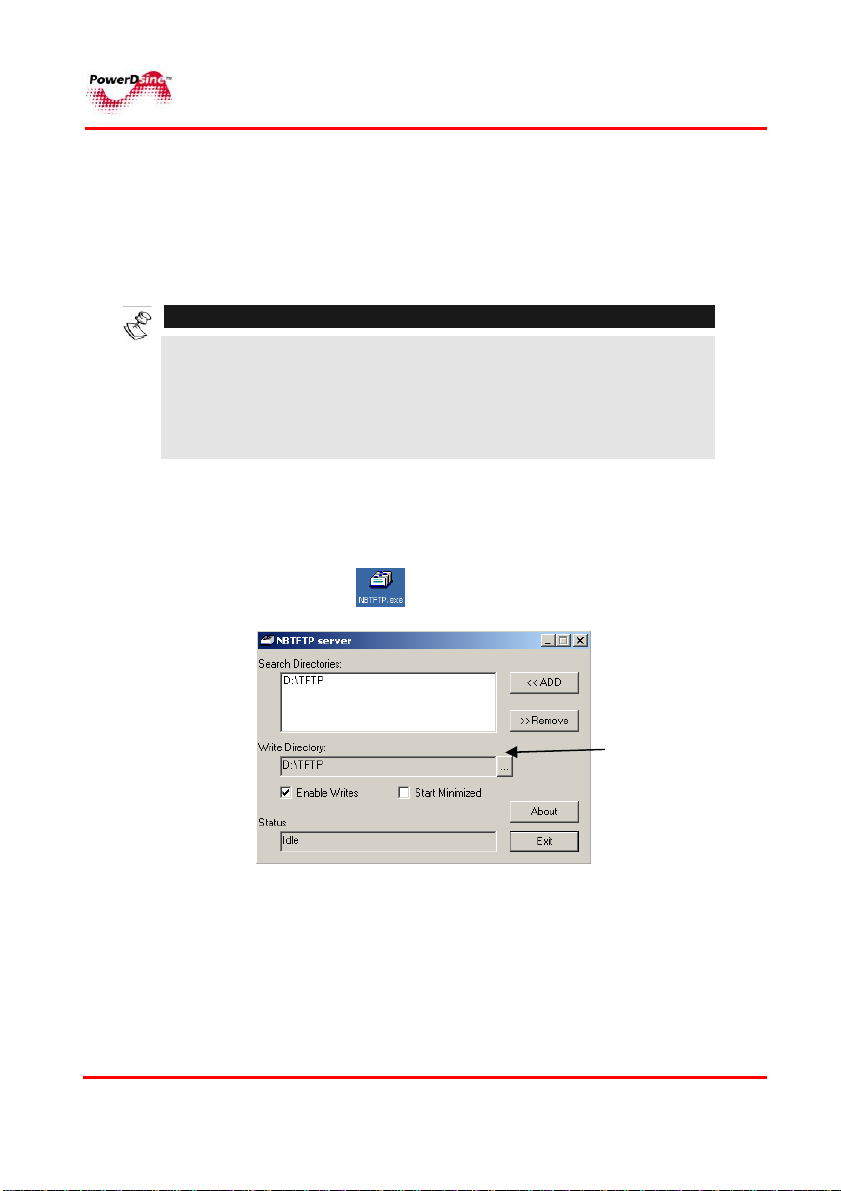
3.5 TFTP Server Configuration
The TFTP Server allows tranfer of files stored by the Host to/from
the PoE unit. This paragraph describes how to configure the TFTP
server which is utilized for optional software updates.
NOTES:
1. Make sure Firewall is turned off on the computer which
runs the TFTP Server (or enable UDP port 69 to pass
through the Firewall).
2. For Upload Configuration – make sure Enable Writes
checkbox is checked when (see Para. 3.4.6)
1 Copy the NBTFTP.exe application from the provided
CD to your server’s desktop.
PPoowweerrDDssiinnee
2 Click on the
The following window appears;
.
Browse
button
3 Click the Browse button and select your preferred
location for the files. Click OK when done.
4 The Server utilizes the IP address of the computer
on which TFTP software is running.
PPoowweerr oovveerr EEtthheerrnneett SSoolluuttiioonnss
23
Page 24

RReemmoottee WWeebb MMaannaaggeerrss
44 GGUUII DDeessccrriippttiioonn
4.1 Overview
The GUI (Graphic User Interface) provides complete monitoring,
control and configuration of PowerDsine’s Power over Line (PoE)
products. The GUI is user friendly and presents graphical elements
of the actual device in addition to information tables. The system
provides several features:
♦ Graphical view of the monitored device
♦ Graphical configuration of the monitored device
♦ Properties of the management system.
The GUI provides two authorization levels as follow (see also
Paragraph 4.4.4.1):
User - allowed to access only to the View menus
Administrator allowed to view and modify all the GUI
functions
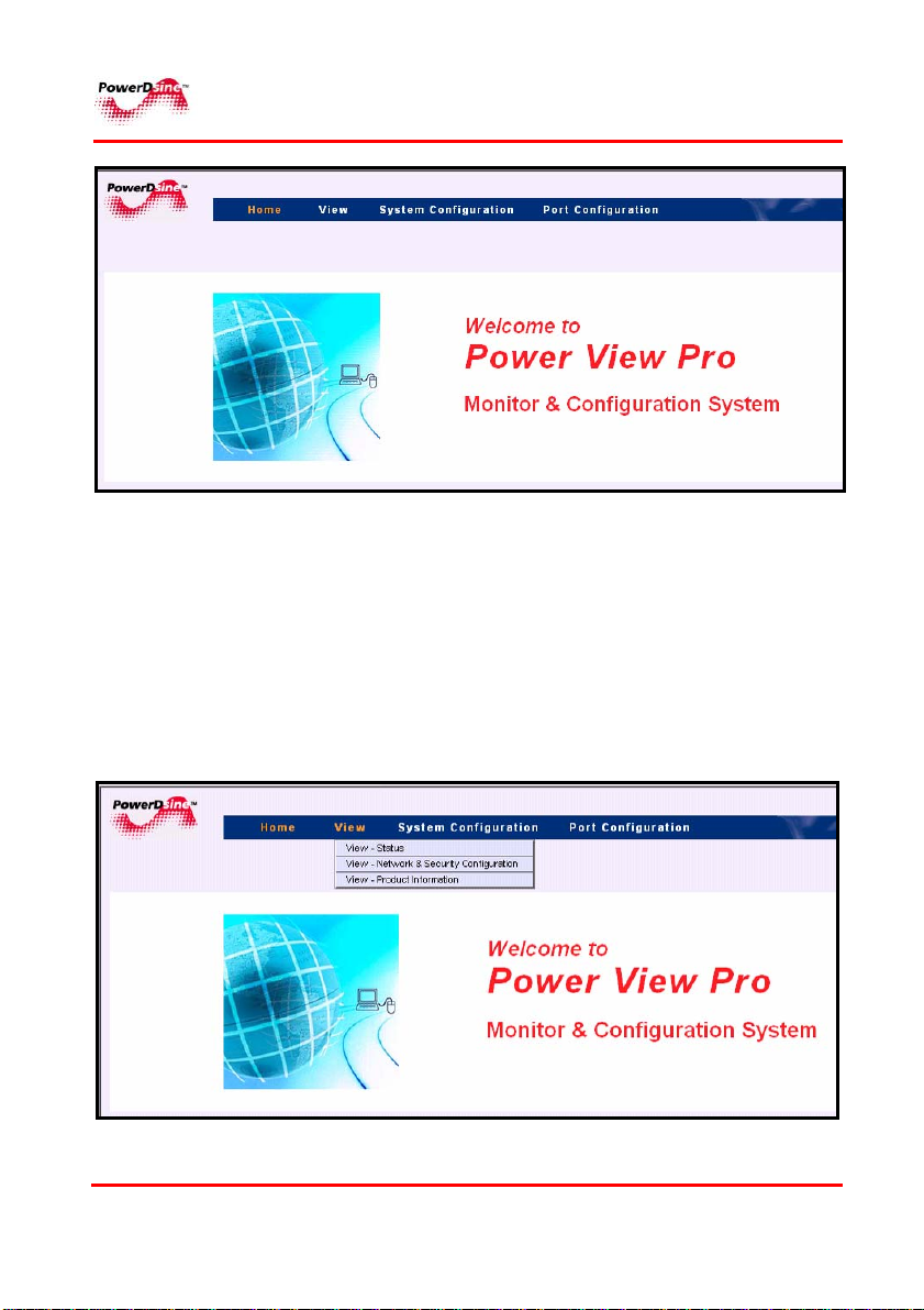
4.2 Opening Screen
The Main screen (Opening screen) window is shown in Figure 4-1.
The Opening screen features three main menus as follows:
♦ View menu – used to view status, network configuration and
product information
♦ System Configuration menu – allows system Configuration
(network, SNMP, security, product parameters and
maintenance (it is password protected)
♦ Port Configuration menu – allows enabling/disabling of
ports, allocation of power, setting of priorities and more.
PPoowweerrDDssiinnee
PPoowweerr oovveerr EEtthheerrnneett SSoolluuttiioonnss
24
Page 25
RReemmoottee WWeebb MMaannaaggeerrss
Figure 4-1: Opening Screen
4.3 View Screen
View menu: – used to view the following categories
(see Figure 4-2):
Status
Network Configuration
Product Information
PPoowweerrDDssiinnee
Figure 4-2: View Menu
PPoowweerr oovveerr EEtthheerrnneett SSoolluuttiioonnss
25
Page 26
RReemmoottee WWeebb MMaannaaggeerrss
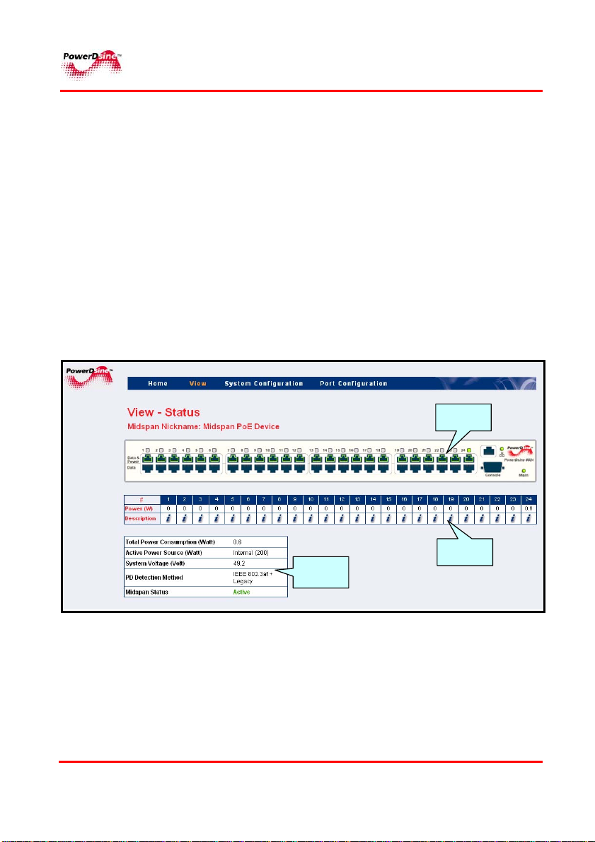
4.3.1 View Status Screen
The View Status screen is the main Midspan monitoring tool. It
comprises three elements (see Figure 4-3):
Ports status panel
Ports power status table
General power status table
The Ports status panel displays the following parameters:
Ports Status
Link Status
AC/DC Input Power Status.
Port status
panel
PPoowweerrDDssiinnee
Ports powe r
General
power
status t able
status t able
Figure 4-3: View Status Screen
PPoowweerr oovveerr EEtthheerrnneett SSoolluuttiioonnss
26
Page 27
RReemmoottee WWeebb MMaannaaggeerrss
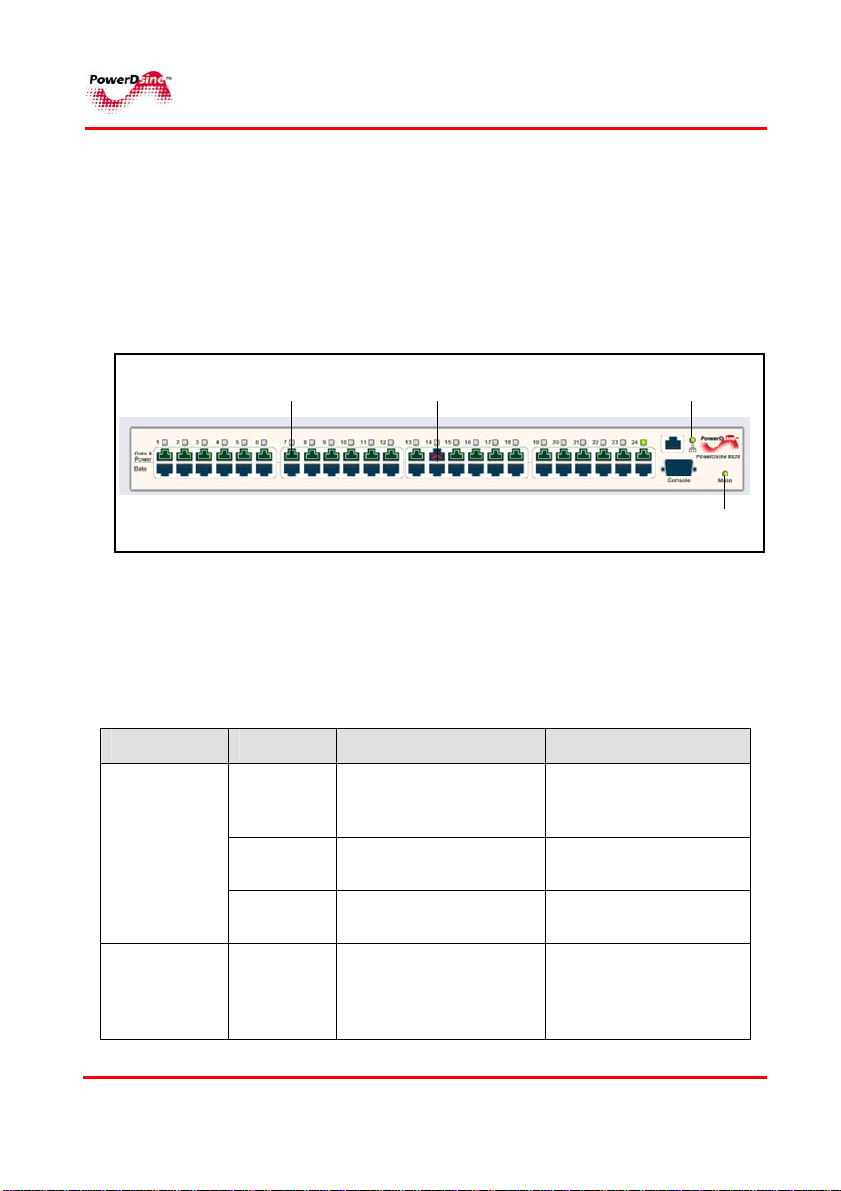
4.3.1.1 Ports Status Panel
The display panel includes a number of visual indicators as shown
in Figure 4-4; Green illuminated port indicates that the terminal unit
has been identified as "Power over Ethernet Enabled" and is active
and receiving power. Disabled ports illuminate red, indicating that
the port is not supplying power and is not active. An “X” symbol
appears (indicates inactive port) as well.
4.3.1.2 Power & Communication Indications
Two LED's are located on the front panel, marked “Main” and Link
as described in Table 4-1 and Table 4-2.
Enabled
port
Disabled
port
Figure 4-4: Ports Status Panel
Table 4-1: Main Status Indications
Link LED
Main
LED
Indicator Color Main Power Status Remarks
AC LED
DC LED
PPoowweerrDDssiinnee
Off
Green
Green
blinking
Green
Internal power supply
unit is unplugged or
faulty
Indicates AC power
input active
Internal power supply
voltage is out of range
Indicates normal
48VDC power
supplied to PDs
PPoowweerr oovveerr EEtthheerrnneett SSoolluuttiioonnss
27
Internal power supply
voltage is too low. All
ports are disconnected
Internal power supply
voltage is within limits
All ports are
disconnected
Applicable only for
Midspan unit with
48VDC optional
module
Page 28

RReemmoottee WWeebb MMaannaaggeerrss
Indicator Color Main Power Status Remarks
LINK LED
(PD-6024G,
PD-8012
only)
Green
blinking
Orange
Green
blinking
Green
External power supply
DC voltage is out of
range
Indicates that load
consumes more
power than allocated
Indicates valid
Ethernet link, and
some data
communication flow
over the Ethernet
network
Indicates valid
Ethernet link(no
communication data)
Table 4-2: 60xxG Gigabit Midspan Port Status Indications
Port LED Color
Off
Green
Orange
Orange
blinking
PPoowweerrDDssiinnee
Port Load Conditions Port Voltage
Non-active load,
unplugged port, or
disabled port
Active load is plugged in
and complies with
normal load conditions
Overload conditions; or
short; or forced external
voltage feed (constant
DC) into the port
Port can't be activated
since total aggregated
power exceeds
maximum power budget
28
Power to the port is
disconnected. No DC
voltage present on spare
pairs
Continuous nominal DC
voltage is present on the
spare pairs
Power to the port is
disconnected. No DC
voltage is present on the
spare pairs
Power to the port is
disconnected. No DC
voltage is present on the
spare pairs
PPoowweerr oovveerr EEtthheerrnneett SSoolluuttiioonnss
Page 29

RReemmoottee WWeebb MMaannaaggeerrss
Table 4-3: 65xx Midspan Port Status Indications
Port LED
Color
Port Load Conditions Port Voltage
Off
Green
Green
blinking
Slow
orange
blinking
Non-active load, unplugged
port or disabled port
Active load is plugged in and
complies with normal load
conditions
Overload conditions; or
short; or forced external
voltage feed (constant DC)
into the port
Port can't be activated since
total aggregated power
exceeds maximum power
budget
Power to the port is
disconnected. No DC
voltage present on spare
pairs
Continuous nominal DC
voltage is present on the
spare pairs
Power to the port is
disconnected. No DC
voltage is present on the
spare pairs
Power to the port is
disconnected. No DC
voltage is present on the
spare pairs
PPoowweerrDDssiinnee
PPoowweerr oovveerr EEtthheerrnneett SSoolluuttiioonnss
29
Page 30

RReemmoottee WWeebb MMaannaaggeerrss
Table 4-4: 80xx High Power Midspan Port Status Indications
Port LED
Color
Off
Green
Green
blinking
Orange
Orange
blinking
Port Load Conditions Port Voltage
Non-active load or
unplugged port
Active load is plugged and
power is provided both on
the data & spare pairs (PD
device may consume up to
20Watts on each pair, and
up to 40Watts total)
Power is provided only on
data or spare pairs (max
power = 20Watts)
Overload conditions; or
short; or forced external
voltage feed (constant DC)
into the port
Port can't be activated since
total aggregated power
exceeds maximum power
budget
Power to the port is
disconnected. No DC
voltage present on spare
pairs
Continuous nominal DC
voltage is present on the
spare pairs
Continuous nominal DC
voltage is present only on
the data or spare pairs, and
not on both of them
Power to the port is
disconnected. No DC
voltage is present on the
spare pairs
Power to the port is
disconnected. No DC
voltage is present on the
spare pairs
PPoowweerrDDssiinnee
PPoowweerr oovveerr EEtthheerrnneett SSoolluuttiioonnss
30
Page 31

RReemmoottee WWeebb MMaannaaggeerrss
4.3.1.3 Ports Power Status Table
Ports Power Status Table displays the following parameters:
No. Parameter Description
.1 Total Power
Consumption
.2 Active Power
Source
.3 System Voltage
Total power consumed by all PDs
Maximum available Power from internal
Power Supply, or external DC Power
Source (applicable only for Midspan with
48VDC option)
Voltage level supplied to PDs
.4 PD Detection
.5 Midspan Status
PPoowweerrDDssiinnee
Detection method selected by the user
Method
from the System Configuration - Product
Parameters menu (see Para.
Midspan status display with the following
options:
1. Active –
2. Midspan has no firmware - Midspan
has no firmware indication
3. Internal Comm. Failure – internal
communication failure
4. Midspan firmware update - firmware
update indication
normal operation
PPoowweerr oovveerr EEtthheerrnneett SSoolluuttiioonnss
31
4.4.5)
Page 32

RReemmoottee WWeebb MMaannaaggeerrss
4.3.1.4 General Power Status Table
Pressing the
WEB page to appear with detailed port description information:
No. Parameter Description
.1
Port
.2
Power
.3
Max Pwr
.4
Priority
.5
Terminal Type /
Description
.6
Class
i image, or the RJ45 jack, will cause a new popup
Was port Enabled or Disabled
Actual consumed power by individual PD
Maximal allocated power per Port as
configured in the Port Configuration –
Detailed screen (see Para.
Current priority level set by the user
Textual terminal description as
configured in the Port Configuration –
Detailed screen (see Para.
PD device class (applicable only for
Midspan family 65xx)
6.13)
6.13)
PPoowweerrDDssiinnee
PPoowweerr oovveerr EEtthheerrnneett SSoolluuttiioonnss
32
Page 33

RReemmoottee WWeebb MMaannaaggeerrss
4.3.2 View – Network & Security Configuration Screen
View - Network Configuration Screen displays the following
parameters:
IP in-Use – currently used IP address/Mask/ Gateway
Remote Trap SNMP Managers List- list of appointed
managers
Static Network Configuration – manually configured
Network parameters
Remote Access – Remote managers that may access the
Midspan (SNMP v1/v2 and SNMPv3, Telnet) and
enabled/disabled SSL WEB encryption
Remote Servers – IP address of remote SysLog Server, IP
address of remote NTP ( Network Time Protocol) Server.
Date & Time – Unit system time (GMT), as acquired from
the NTP Server
PPoowweerrDDssiinnee
PPoowweerr oovveerr EEtthheerrnneett SSoolluuttiioonnss
33
Page 34

RReemmoottee WWeebb MMaannaaggeerrss
g
4.3.2.1 IP in-Use
IP in-Use window displays the current IP address being used with
the following parameters:
No. Parameter Description
.1
Obtain IP by
DHCP
.2
IP Address
.3
IP Mask
.4
Default Gateway
Indicates how the IP is obtained as
previously set by the user (see System
Confi
IP address, numerical address which
indicates a particular computer within a
network
The definition of the network portion of
the IP address. This location must be
configured in such a way that all IP
addresses up to and including the local
gateway are allowed.
The IP address of the local Gateway,
which enables communication settings to
other LAN segments.
uration –Network - Para 6.6).
4.3.2.2 Remote Trap SNMP Managers List
This List displays all the user pre-configured managers (see Para.
6.7 for further details). All listed managers receive standard and
private traps from the Midspan.
PPoowweerrDDssiinnee
PPoowweerr oovveerr EEtthheerrnneett SSoolluuttiioonnss
34
Page 35

RReemmoottee WWeebb MMaannaaggeerrss
g
4.3.2.3 Static Network Configuration
Static Network Configuration window displays Network configuration
in cases where Static IP is selected (and not DHCP). In cases
where the unit is configuered as Static IP, both IP-In Use and Static
configuration tables will be identical.
The following static parameters appears:
No. Parameter Description
.1
.2
.3
.4
PPoowweerrDDssiinnee
IP Address
IP Mask
Default
Gateway
MAC Address
Internet address, numerical address which
indicates a particular computer within a network
The definition of the network portion of the IP
address. This location must be configured in
such a way that all IP addresses up to and
includin
IP address of the local Gateway, which enables
communication settings to other LAN segments.
Media access control address. A 12-digit
hexadecimal address used by the media access
control layer of an 802.2 connection. connection
with Host Integration Server.
the local gateway are allowed.
PPoowweerr oovveerr EEtthheerrnneett SSoolluuttiioonnss
35
Page 36

RReemmoottee WWeebb MMaannaaggeerrss
4.3.2.4 Remote Access
The Remote Access window displays the remote managers that may
access the unit (SNMPv1/v2 , SNMPv3, Telnet) and enabled/disabled SSL
WEB encryption.
No. Parameter Description
.1
Enable SNMPv2
Indicates enabled/disabled SNMP v1/v2
.2
Enable SNMPv3
.3
Enable Telnet
.4
Enable Web SSL
Encryption
PPoowweerrDDssiinnee
Indicates enabled/disabled SNMPv3, due to
security considerations. Note that it is not
recommended to enable SNMPv2 while
SNMPv3 is in use!
When this box is checked, the user may
access the unit, via the Telnet protocol.
When this box is checked, indicates that
WEB pages are encrypted by SSL.
PPoowweerr oovveerr EEtthheerrnneett SSoolluuttiioonnss
36
Page 37

RReemmoottee WWeebb MMaannaaggeerrss
4.3.2.5 Remote Servers
Remote Servers window displays the IP address of a remote SysLog Server,
and an IP address of remote NTP ( Network Time Protocol) Server.
No. Parameter Description
.1
NTP Server
.2
SysLog Server
IP address of a remote Network Time
Protocol (NTP) Server
Log Events sent to the IP address via SysLog
protocol
Note that an IP address 0.0.0.0 prohibits the
unit from sending Log Events
4.3.2.6 Date and Time
Date and Time window displays unit system time (GMT), as acquired from
the NTP Server.
No. Parameter Description
.1
Time (GMT)
.2
Date (D/M/Y)
Time (HH:MM:SS) as acquired from the NTP
Server
Date (DD/MM/YYYY) as acquired from the
NTP Server
If the unit fails to acquire time from the NTP
Server, it will display the elapsed time since
1/1/2005
PPoowweerrDDssiinnee
PPoowweerr oovveerr EEtthheerrnneett SSoolluuttiioonnss
37
Page 38

RReemmoottee WWeebb MMaannaaggeerrss
4.3.3 View - Product Information
View - Product Information screen displays the following parameters
(see Figure 4-5):
Figure 4-5: View - Product Information Screen
No. Parameter Description
.1
Product Nickname
.2
Serial Number
.3
Software Version
Unit nickname as configured by
network administrator
Midspan serial number
Current software version
PPoowweerrDDssiinnee
PPoowweerr oovveerr EEtthheerrnneett SSoolluuttiioonnss
38
Page 39

RReemmoottee WWeebb MMaannaaggeerrss
4.4 System Configuration Screen
System Configuration Screen allows the following Configurations:
(Figure 4-6):
Network Configuration
SNMP Configuration
SNMPv3 Configuration
Security Configuration
Product Parameters-Configuration
System Configuration - Maintenance
Figure 4-6: System Configuration Screen
4.4.1 System Configuration Network Screen
Network Configuration screen (see Figure 4-7) allows Configuration
of the following parameters (see also para. 4.3.2.1): IP Address,
Subnet Mask, Default Gateway.
PPoowweerrDDssiinnee
PPoowweerr oovveerr EEtthheerrnneett SSoolluuttiioonnss
39
Page 40

RReemmoottee WWeebb MMaannaaggeerrss
Figure 4-7: System Configuration Network Screen
No. Button/Checkbox Description
.1
.2
.3
.4
.5
NTP Server IP address of a remote NTP Server
.6
SysLog Server IP address of a remote SysLog
PPoowweerrDDssiinnee
When checked enables the DHCP
to obtain IP by server; Note that the
Static IP Address fields are dimmed!
Static IP address to be used in
cases where DHCP is disabled.
Static IP subnet mask to be used in
cases where DHCP is disabled.
Static IP default gateway to be used
in cases where DHCP is disabled
server to which the Midspan sends
log events.
Note that an IP address 0.0.0.0
prohibits the unit from sending Log
PPoowweerr oovveerr EEtthheerrnneett SSoolluuttiioonnss
40
Page 41

RReemmoottee WWeebb MMaannaaggeerrss
No. Button/Checkbox Description
events.
.7
.8
4.4.1.1 Log Server
The Midspan can send various internal event reports to an external
Host running SysLog deamon application which logs those events
for future use. An example of such SysLog server application can be
found at http://www.kiwisyslog.com/
SysLog messages are sent whenever the SysLog Server’s IP is
other than ‘0.0.0.0’. The following events may be sent by the
Midspan:
• System was restarted
• PSE port SNMP status has changed
• Midspan delivers power above xy% threshold
• Midspan delivers power less then xy% threshold (after
exceeded power message was sent)
• Remote user tried to access WEB view pages using an incorrect
password
• Remote user tried to access WEB configuration pages using
incorrect password
• Unit’s was restored to factory default values
• Unit configuration was changed
• Remote Telnet user failed to login (incorrect user or password)
Update new Network parameters.
All Properties and Remote Servers
parameters become effective only
after this button has been clicked.
Cancels current operation and
restores previous values in cases
where the Update & Save buttons
were not clicked.
PPoowweerrDDssiinnee
PPoowweerr oovveerr EEtthheerrnneett SSoolluuttiioonnss
41
Page 42

RReemmoottee WWeebb MMaannaaggeerrss
NOTE:
Each SysLog message contains the message itself and date &
time (GMT). The Midspan acquires date & time from the Network
NTP Server.
4.4.1.2 NTP Server
Whenever a valid NTP Server IP is configured, the Midspan
acquires date & time (GMT) from the Network NTP Server. In cases
where no valid IP is set, or in cases where the Midspan fails to
acquire time from the NTP Server, initial Midspan time will be set to
1/1/2005 as default.
PPoowweerrDDssiinnee
PPoowweerr oovveerr EEtthheerrnneett SSoolluuttiioonnss
42
Page 43

RReemmoottee WWeebb MMaannaaggeerrss
4.4.2 System Configuration SNMP
The Unit’s SNMP agent (v1/v2/v3) enables a remote SNMP
management station to monitor a unit, enable/disable PoE ports
(RFC3621), view various PoE MIB statistics and MIB-II Network
statistics. Private MIB extends PoE funtionality beyond RFC3621
PoE MIB. The SNMPv3 offers a secured method for configuration
and monitoring. SNMP Network packets may be authenticated by
MD5 and encrypted by DES.
System Configuration SNMP screen allows configuration of SNMP
parameters that are common both to SNMPv1/v2 and SNMPv3
(SNMPv1/2 community string is the only exception). The following
parameters can be configured (see Figure 4-8):
Community Strings
System Information
Remote Trap SNMP Managers List
PPoowweerrDDssiinnee
Figure 4-8: System Configuration SNMP Screen
PPoowweerr oovveerr EEtthheerrnneett SSoolluuttiioonnss
43
Page 44

RReemmoottee WWeebb MMaannaaggeerrss
4.4.2.1 Community Strings (SNMPv2c)
Community strings are actually SNMP passwords. To enable remote
SNMP manager communication with the device, the user must
configure his community strings to match those of the Midspan.
Community Strings window allows configuration of the following
parameters:
No. Field Description
.1
.2
.3
PPoowweerrDDssiinnee
Get community
Set community
Trap
community
Used by remote SNMP NMS station for
GET commands (get information from
Midspan)
Used by remote SNMP NMS station for
SET commands (change contact
person, device name, etc.)
Each TRAP sent by the MIdspan to
remote NMS managers contains Trap
community string. Remote SNMP NMS
managers may use it in order to filter out
unnecessary TRAP events.
PPoowweerr oovveerr EEtthheerrnneett SSoolluuttiioonnss
44
Page 45

RReemmoottee WWeebb MMaannaaggeerrss
4.4.2.2 System Information (MIB-II)
System Information window allows configuration of the following:
No. Button/Checkbox Description
.1
SysContact
.2
SysName
.3
SysLocation
4.4.2.3 PoE MIB Checkboxes
This window allows graphical configuration of two major RFC3621
PoE MIB parameters as follow:
No. Button/Checkbox Description
.1
Enable Notification
Allows/prohibits unit from sending
PoE traps (both SNMPv2c and
SNMPv3)
.2
Notify Exceeded
Power Usage (1-99%)
The Midspan sends TRAP each
time total power consumption
exceeds xy%, in cases where
Enable Notification checkbox is
checked,
SNMP MIB-II 1.3.6.1.2.1.1.4:
Textual identification of the contact
person for this managed node,
together with information on how
to contact this person.
SNMP MIB-II 1.3.6.1.2.1.1.5:
Textual identification of an
administratively-assigned name for
current managed node
SNMP MIB-II 1.3.6.1.2.1.1.6:
Textual identification of the
physical location of current node
PPoowweerrDDssiinnee
PPoowweerr oovveerr EEtthheerrnneett SSoolluuttiioonnss
45
Page 46

RReemmoottee WWeebb MMaannaaggeerrss
4.4.2.4 Remote Trap SNMP Managers List
This window allows configuration of up to 10 remote SNMP
managers. Each Trap will be duplicated and sent by the Midspan to
all the remote SNMP managers (in case both SNMPv2c and
SNMPv3 are set, each Trap will be sent twice. Once by SNMPv2c,
and once by SNMPv3).
No. Button Description
.1
.2
Updates Midspan properties status and
saves configuration in cases where Midspan
restarts working.
All SNMP parameters become effective only
after this button has been clicked!
Cancels current operation and restores
previous values
NOTE:
SNMPv2C activation is done from the Security WEB page.
PPoowweerrDDssiinnee
PPoowweerr oovveerr EEtthheerrnneett SSoolluuttiioonnss
46
Page 47

RReemmoottee WWeebb MMaannaaggeerrss
4.4.3 System Configuration SNMPv3
System Configuration SNMPv3 screen allows configuration of three
different SNMPv3 user types and notification (Trap) which requires
same parameters as any other SNMPv3 user.
PPoowweerrDDssiinnee
Figure 4-8: System Configuration SNMPv3 Screen
Guest User – Allows limited read only access to MIB-II
System OiD tree. It should be used by SNMP managers
who prefer not to expose their real username & password in
order to pool the device for "keep alive" report. Guest user
has no authentication or privacy (encryption) ability.
View User – Has reading (GET) access to all SNMP
branches but cannot perform any modifications (SET).
User Name – SNMPv3 user (mandatory field)
Authentication Password (MD5) – applicable when
MD5 or MD5+DES is being used.
Privacy Password (DES) – applicable only when
PPoowweerr oovveerr EEtthheerrnneett SSoolluuttiioonnss
47
Page 48

RReemmoottee WWeebb MMaannaaggeerrss
MD5+DES is being used.
Authentication+Encryption – Allows selection of one of
three security levels as follow:
None – SNMPv3 packets are not authenticated
neither encrypted
MD5 – SNMPv3 packets are authenticated but
not encrypted
MD5+DES – SNMPv3 packets are authenticated
and encrypted
Admin User – Has full reading (GET) and writing (SET)
access to all SNMP branches
User Name – SNMPv3 user (mandatory field )
Authentication Password (MD5) – applicable
when MD5 or MD5+DES is being used.
Privacy Password (DES) – applicable only when
MD5+DES is being used.
Authentication+Encryption – Allows selection of
one of three security leveles:
PPoowweerrDDssiinnee
None – SNMPv3 packets are not
authenticated neither encrypted.
MD5 – SNMPv3 packets are authenticated
but not encrypted
MD5+DES – SNMPv3 packets are
authenticated and encrypted
Notification Trap – SNMPv3 trap configuration parameters
are identical to SNMPv3 user
User Name – SNMPv3 user (mandatory field )
Authentication Password(MD5) – applicable when
MD5 or MD5+DES is being used.
Privacy Password (DES) – applicable only when
PPoowweerr oovveerr EEtthheerrnneett SSoolluuttiioonnss
48
Page 49

RReemmoottee WWeebb MMaannaaggeerrss
MD5+DES is being used.
Authentication+Encryption – allows selection of one of
three security leveles:
None – SNMPv3 packets are not
authenticated and neither encrypted
MD5 – SNMPv3 packets are authenticated
but not encrypted
MD5+DES – SNMPv3 packets is
authenticated and encrypted
NOTE:
SNMPv3 activation is performed via the Security WEB page.
Notification (Trap) remote manager can be configured via the
System Configuration – SNMP WEB page NTP Server.
PPoowweerrDDssiinnee
PPoowweerr oovveerr EEtthheerrnneett SSoolluuttiioonnss
49
Page 50

RReemmoottee WWeebb MMaannaaggeerrss
4.4.4 System Configuration Security
System Configuration Security screen allows Configuration of the
following parameters (see Figure 4-9):
Secure Access & Configuration
Remote Access communication type
Figure 4-9: System Configuration Security Screen
4.4.4.1 Secure Access & Configuration
The user can protect one or both of the View and Configuration
menus by clicking the desired appropriate checkbox; there are two
types of system users as follows:
System User who is allowed to use the View menu only and System
administrator who is allowed to view and use all the GUI functions.
Password and user name are also set in this window and the user is
prompted to type the appropriate password and user name when
accessing the protected menus.
PPoowweerrDDssiinnee
PPoowweerr oovveerr EEtthheerrnneett SSoolluuttiioonnss
50
Page 51

RReemmoottee WWeebb MMaannaaggeerrss
NOTE:
A remote Telnet user is requested to provide username and
password, regardless of the check box selection state. Checking
the View username & password checkbox, prevents remote
Telnet user to perform any modifications. Checking Configuration
username & password provides full access to remote Telnet user.
4.4.4.2 Remote Access
Enable SNMPv2 – Enables management of the unit via remote
SNMP manager station that utilizes SNMPv2c application.
Enable SNMPv3 - Enables management of the unit by remote
SNMP manager station that utilizes SNMPv3 application.
NOTE:
Due to security considerations, when SNMPv3 is in use, it is
recommended to disable SNMPv2.
PPoowweerrDDssiinnee
PPoowweerr oovveerr EEtthheerrnneett SSoolluuttiioonnss
51
Page 52

RReemmoottee WWeebb MMaannaaggeerrss
Enable Telnet - This commuication is enabled by default. To
disable remote Telnet commuication, uncheck the Enable Telnet
checkbox.
Enable Web SSL Encryption– When checked, provides security
for Web pages, utilizing the SSL
No. Button Description
.1
.2
Updates Midspan parameters and saves
configuration. All Remote Access parameters
become effective only after this button has
been clicked.
Cancels current operation and restores
previous values (in cases where
was not clicked).
PPoowweerrDDssiinnee
PPoowweerr oovveerr EEtthheerrnneett SSoolluuttiioonnss
52
Page 53

RReemmoottee WWeebb MMaannaaggeerrss
4.4.5 System Configuration Product Parameters
Product parameters set by the user include (see Figure 4-10):
Midspan Nickname
System Detection Method
Status View Refresh Rate.
Figure 4-10: System Configuration Product Parameters Screen
PPoowweerrDDssiinnee
PPoowweerr oovveerr EEtthheerrnneett SSoolluuttiioonnss
53
Page 54

RReemmoottee WWeebb MMaannaaggeerrss
No. Button/Checkbox Description
.1
.2
.3
Assists network managers
to identify Midspan.
PD Detection Method: IEEE
802.3af, or IEEE 802.3af
+Legacy drop-down menu
(IEEE 802.3af
+Legacy=default)
Allows Setting of System
Status WEB page refresh
rate
Updates Midspan product
based parameetrs.
All the product parameters
become effective only after
this button has been
clicked!
Cancels current operation
and restores previous
values
PPoowweerrDDssiinnee
PPoowweerr oovveerr EEtthheerrnneett SSoolluuttiioonnss
54
Page 55

RReemmoottee WWeebb MMaannaaggeerrss
4.4.6 System Configuration Maintenance
System Configuration Maintenance screen (see Figure 4-11) allows
two maintenance means destined to maintain the Midspan.
Reseting the Manager Module
Reseting the Midspan
Restoring Factory Defaults
When trouble is encounered, or when the Midspan does not function
properly, reseting the Midspan or restoring factory default values
may solve the problem.
Figure 4-11: System Configuration Maintenance Screen
PPoowweerrDDssiinnee
PPoowweerr oovveerr EEtthheerrnneett SSoolluuttiioonnss
55
Page 56

RReemmoottee WWeebb MMaannaaggeerrss
No. Button/Checkbox Description
.1
Resets only the
Manager Module
without affecting
Midspan PoE
ports
.2
.3
Resets unit
temporarily. All
active PoE ports
momentarely stop
providing Power
to PoE devices
(configuration
does not change)
Restore most
Midspan
parameters to
their default value
(IP isn't changed)
PPoowweerrDDssiinnee
PPoowweerr oovveerr EEtthheerrnneett SSoolluuttiioonnss
56
Page 57

RReemmoottee WWeebb MMaannaaggeerrss
4.5 Port Configuration Screen
Port Configuration screen allows the following (Figure 4-12):
♦ Port Configuration Enable/Disable
♦ Port Configuration Detailed
Port Configuration Enable/Disable screen provides a quick access
to ports in order to Enable/Disable one or more of them.
Port Configuration Detailed screen allows detailed Configuration of
various system values such as priority, allocated power and port/PD
description.
PPoowweerrDDssiinnee
Figure 4-12: Port Configuration Screen
PPoowweerr oovveerr EEtthheerrnneett SSoolluuttiioonnss
57
Page 58

RReemmoottee WWeebb MMaannaaggeerrss
4.5.1 Port Configuration Enable/Disable
Each port may be individually Enabled/Disabled, or all ports may be
enabled or disabled in one action.
Once the ports are disabled, the Midspan View Status screen is
updated accordingly (see Para. 4.3 / Figure 4-3).
Enabled ports Disabled ports
Figure 4-13: Port Configuration Enable/Disable Screen
PPoowweerrDDssiinnee
PPoowweerr oovveerr EEtthheerrnneett SSoolluuttiioonnss
58
Page 59

RReemmoottee WWeebb MMaannaaggeerrss
No. Button/Checkbox Description
.1
.2
NOTE:
If only update button is pressed, a blinking image appears near
the Save & update button, reminding the user that latest changes
were not saved. Reversing latest changes and pressing Update,
eliminates the blinking image. Saving latest changes eliminates
this image as well.
Enabled – enables all ports
Disabled - disables all ports
Note - Only WEB page is effectd
Update – Clicking this button,
activates the new user settings
but does not store new
configuration (unit reset
overides latest changes)
Cancel – Cancels current
operation and restores previous
values in cases where
Update&Save were not clicked
Update & Save – Updates
Midspan properties status and
saves configuration in cases
where Midspan restarts.
PPoowweerrDDssiinnee
PPoowweerr oovveerr EEtthheerrnneett SSoolluuttiioonnss
59
Page 60

RReemmoottee WWeebb MMaannaaggeerrss
4.5.2 Port Configuration Detailed
The Port Configuration Detailed screen (see Figure 4-14: , Figure
4-15: ) allows the user to control individual ports and set-up
parameters as follows:
♦ Activate/shut-down individual ports
♦ Allocate Maximal power per port (not applicable for 80xx)
♦ Set-up the priority of each port
♦ Define port description and Terminal type
In order to simplify the configuration of multiple ports, each
parameter may be set by pressing a single button (SET), thus
applying the selected values to all ports (action on all ports).
Figure 4-14: Port Configuration Detailed Screen (60xxG, 65xx family)
PPoowweerrDDssiinnee
PPoowweerr oovveerr EEtthheerrnneett SSoolluuttiioonnss
60
Page 61

RReemmoottee WWeebb MMaannaaggeerrss
Figure 4-15: Port Configuration Detailed Screen (80xx Midspan family)
4.5.2.1 Ports Activation
Ports activation/deactivation is performed by the user according to
actual requirements. Each port can be switched to Enable or
Disable state.
This is simply done by checking the colored checkboxes on the left
hand side of the screen.
4.5.2.2 Allocating Maximum Power (60xxG , 65XX Midspan family)
Power allocation is performed by selecting the maximum allowed
power per port from the drop-down menu, located on the Max.
Power column. Available power values are as folllows:
Default: 16.8 W
Minimum: 1 W
Maximum: 16.8 W
PPoowweerrDDssiinnee
PPoowweerr oovveerr EEtthheerrnneett SSoolluuttiioonnss
61
Page 62

RReemmoottee WWeebb MMaannaaggeerrss
4.5.2.3 Setting Priority
The user can assign priorities to desired PDs in cases where the
Midspan is operating with a limited source of power. Priority
selection is performed from the drop-down menu, located on the
Priority column; Three priority states are available:
Critical
High
Low (default)
The Midspan allocates all available power to the PDs, according to
the PoE ports sequential number. If total power consumption is
exceeded, the unit enters its Power Management mode (providing
power to high priority ports).
Under this mode, ports having higher priority, provide power to their
respective PDs.
4.5.2.4 Terminal Type / Description
In this column, the operator can enter any free text such as: terminal
location, name of user, telephone No., etc. representing the
corresponding port (default=Port x).
Note that it has no effect on power itslelf and it functions as an
assistence tool for the IT manager.
PPoowweerrDDssiinnee
PPoowweerr oovveerr EEtthheerrnneett SSoolluuttiioonnss
62
Page 63

RReemmoottee WWeebb MMaannaaggeerrss
55 SSNNMMPP MMoonniittoorriinngg aanndd
CCoonnffiigguurraattiioonn GGUUII
5.1 General
The midspan manager module supports SNMPv1, SNMPv2c,
SNMPv3. In order to use SNMP please check the following:
5.2 SNMP MIB's
Several MIB's are supported by Midspan SNMP manager.
• Browse to System Configuration security WEB page, and
make sure SNMP is enabled
• For SNMPv2c, browse to System Configuration SNMP WEB
page. Make sure community strings match your SNMP
manager configuration.
• For SNMPv3, brows to System Configuration SNMPv3
WEB page and make sure username, authentication and
privecy password, encryption method match your SNMP
manager startion configuration.
• Brows to SNMP WEB page. Enable PoE MIB traps, and set
remote manager IP address in the Trap list.
• RFC3621 – Power Over Ethernet MIB which provides
various management capabilities ( see bellow)
• Private MIB – Enhance PoE funtionality beyond RFC3621
PoE MIB.
• RFC1213 – MIB2 which provides general network stattistics,
and information on the device being managed.
• Various SNMPv3 MIB's as RFC3413, RFC3414, RFC3415
PPoowweerrDDssiinnee
PPoowweerr oovveerr EEtthheerrnneett SSoolluuttiioonnss
63
Page 64

RReemmoottee WWeebb MMaannaaggeerrss
5.3 RFC3621 PoE MIB
NOTE:
For detailed PoE MIB description, please refer to PowerDsine’s
Technical Note – 132, which describes PoE functionality in detail.
PoE MIB is located at 1.3.6.1.2.1.105 tree. The MIB is devided into
3 sections (see Figure 5-1: ).
st
The 1
Enable/Disable, read port status, class, etc. Each OiD is accessed
as a two dimentional array table.
The 2
provide power to a group of PoE ports. It allows to read total power
consumptioj, power supply status, etc.
The 3
SNMP managers.
section deals with PoE ports and provide funtionality as
nd
section deals with power source which is responsible to
rd
section enable/disable from PoE traps to be send to remote
PoE MIB provides access to the
PPoowweerrDDssiinnee
following elements:
– Ports Parameters
– Main PSE Parameters
– PoE Traps
Figure 5-1: MIB Tree Structure
PPoowweerr oovveerr EEtthheerrnneett SSoolluuttiioonnss
64
Page 65

RReemmoottee WWeebb MMaannaaggeerrss
5.4 Private MIB
Powerdsine private MIB extend RFC3621 PoE MIB with the
following additional management funtionalities (see Figure 5-2: ):
PPoowweerrDDssiinnee
Figure 5-2: MIB’s Management Funtionalities
• Resolves MIB-II SysobjID description
• Readout of each individual port power consumption
• Set maximim power that PD device may consume
• Read Power Supply voltage
• Read/Set detection method (802.3af or 202.3af plus
legacy).
PPoowweerr oovveerr EEtthheerrnneett SSoolluuttiioonnss
65
Page 66

RReemmoottee WWeebb MMaannaaggeerrss
6
6.1 General
To manage multiple Midspan devices it is recommended to use 3rd
party standard Network management tools such as HP Openview or
SNMPc (see Figure 6-1).
OOppeerraattiioon
n
PPoowweerrDDssiinnee
Figure 6-1: Network Management Tool
PPoowweerr oovveerr EEtthheerrnneett SSoolluuttiioonnss
66
Page 67

RReemmoottee WWeebb MMaannaaggeerrss
6.2 Logging in
1 Connect Midspan RJ-45 Ethernet port to local area
network.
2 Open your Web browser and type the IP Address of the
PoE unit to be managed (unit is shipped with IP
192.168.0.50).
3 The Main menu GUI window appears;
PPoowweerrDDssiinnee
PPoowweerr oovveerr EEtthheerrnneett SSoolluuttiioonnss
67
Page 68

RReemmoottee WWeebb MMaannaaggeerrss
6.3 Viewing System Status
¾ To view system statu s:
1 Select the
menu;
View —Status
option from the
View
dropdown
PPoowweerrDDssiinnee
2 View Status screen appears: the port status panel displays
the current status. Note that in the example, Ports 1, 2 are
disabled. The middle table displays power status and
priority and the description raw displays the terminal type
and description when the cursor points at the “I” symbol.
PPoowweerr oovveerr EEtthheerrnneett SSoolluuttiioonnss
68
Page 69

RReemmoottee WWeebb MMaannaaggeerrss
6.4 Viewing Network & Security Configuration Status
¾ To view Network Configuration status:
1 Select the View – Configuration option from the View
dropdown menu; View – Configuration screen appears,
displaying various network parameters as shown below:
PPoowweerrDDssiinnee
PPoowweerr oovveerr EEtthheerrnneett SSoolluuttiioonnss
69
Page 70

RReemmoottee WWeebb MMaannaaggeerrss
6.5 Viewing Product Information
¾ To view P roduct Information:
1 Select the Product Information option from the View
dropdown menu; View – Product Information screen
appears, displaying Product Information as shown below:
6.6 Configuring System - Network
¾ To access S ystem Configuration - Network:
1 Select the System Configuration- Network option from
the System Configuration dropdown menu;
PPoowweerrDDssiinnee
2 User authentication window appears:
PPoowweerr oovveerr EEtthheerrnneett SSoolluuttiioonnss
70
Page 71

RReemmoottee WWeebb MMaannaaggeerrss
3 Type in the appropriate User name (“admin”) and password
(“password”) and then click
4 If an incorrect User name and/or password have been
typed, the following message appears, prompting the user to
conduct another attempt to log in.
.
NOTE:
Three unsuccessful attempts to log in cause the application to
close and the following message appears:
“Your Authentication failed Your Request was denied.
You do not have permission to view this page”.
To log in again, exit the program and try again.
PPoowweerrDDssiinnee
5 System Configuration screen appears when logged in:
PPoowweerr oovveerr EEtthheerrnneett SSoolluuttiioonnss
71
Page 72

RReemmoottee WWeebb MMaannaaggeerrss
6 Set your desired IP Address, Subnet Mask and Default
Gateway or check the Obtain IP by DHCP checkbox.
¾ To configu re NTP Server:
¾ To configu re SysLog Server:
NOTE:
To receive Midspan Log events, please use your preferred SysLog
Server application. For example:
Kiwi Syslog Daemon, via http://www.kiwisyslog.com/ , or any other
SysLog Server application that comply with RFC 3164.
PPoowweerrDDssiinnee
7 Click to save your selection. Clicking
any stage of the configuration, returns the previous value
1 Select the System Configuration- Network option from
the System Configuration dropdown menu.
2 Enter the IP address of the remote NTP Server.
1 Select the System Configuration- Network option from
the System Configuration dropdown menu.
2 Enter the IP address of the remote SysLog Server.
PPoowweerr oovveerr EEtthheerrnneett SSoolluuttiioonnss
72
at
.
Page 73

RReemmoottee WWeebb MMaannaaggeerrss
6.7 Configuring System SNMP
1 Select the System Configuration- SNMP option from the
System Configuration dropdown menu;
2 SNMP window appears:
PPoowweerrDDssiinnee
3 Set your desired Community Strings, System Information
and check the desired option (‘Enable Notification’ or ‘Notify
Exceeded Power Usage’).
4 Click
5 Clicking
previous value
6 Browse to Security WEB page, and enable SNMPv1/v2C
to save your selection.
at any configuration stage, restores the
.
PPoowweerr oovveerr EEtthheerrnneett SSoolluuttiioonnss
73
Page 74

RReemmoottee WWeebb MMaannaaggeerrss
6.8 Configuring System SNMPv3
1 Select the System Configuration- SNMPv3 option from
the System Configuration dropdown menu;
2 SNMPv3 window appears:
PPoowweerrDDssiinnee
2 Fill in your desired Guest User, View User Admin User
and Notification (Trap) in the appropriate fields.
3 Click
4 Clicking
the previous value
5 Browse to Security WEB page, and enable SNMPv3
to save your selection.
at any stage of the configuration, returns
.
PPoowweerr oovveerr EEtthheerrnneett SSoolluuttiioonnss
74
Page 75

RReemmoottee WWeebb MMaannaaggeerrss
6.9 Configuring System Security
1 Select the System Configuration- Security option from the
System Configuration dropdown menu; System
Configuration- Security window appears:
NOTE:
Since SSL security certificate contains WEB server IP address
(which will always be changed by the user), the certificate that
the Midspan manager module offers to the remote WEB SSL
user will be uncertified.
2 Click Yes to continue or No to abort current operation: the
following screen appears:
PPoowweerrDDssiinnee
PPoowweerr oovveerr EEtthheerrnneett SSoolluuttiioonnss
75
Page 76

RReemmoottee WWeebb MMaannaaggeerrss
3 Type in the appropriate User name and password; when
done, click Ok to confirm: the following screen appears:
PPoowweerrDDssiinnee
PPoowweerr oovveerr EEtthheerrnneett SSoolluuttiioonnss
76
Page 77

RReemmoottee WWeebb MMaannaaggeerrss
6.9.1 Protecting View by Password
1 Check the Protect View by Password checkbox.
2 Type in your desired Password and user name in the
Password and Confirm Password fields.
3 Click
4 Clicking
process, returns the previous value.
NOTE:
Password, User Name and Confirm Password fields are dimmed
by default (can not be configured) as long as their corresponding
checkbox is not checked.
to save your selection.
at any stage of the configuration
6.9.2 Modifying Remote Access
1 Check the desired checkbox in the Remote Access section.
2 Click
3 Clicking
the previous value.
6.9.2.1 Enabling Web SSL Encryption
To enable Web SSL Encryption perform the following steps:
4 Check the Enable Web SSL Encryption checkbox.
5 Click
abort current operation): the following screen appears
displaying a security icon at the bottom of the screen:
Note that the URL has also changed (‘s’ added), for example:
to save your selection.
at any stage of the configuration, returns
to save your selection (or
to
PPoowweerrDDssiinnee
https://172.16.17.31/web/config/cfg_security.htm
PPoowweerr oovveerr EEtthheerrnneett SSoolluuttiioonnss
77
Page 78

RReemmoottee WWeebb MMaannaaggeerrss
PPoowweerrDDssiinnee
PPoowweerr oovveerr EEtthheerrnneett SSoolluuttiioonnss
78
Page 79

RReemmoottee WWeebb MMaannaaggeerrss
6.9.2.2 Disabling Web SSL Encryption
To disable Web SSL Encryption perform the following steps:
1 Uncheck the Enable Web SSL Encryption checkbox.
2 Click
screen appears, warning the user that Web pages
transmitted from this point on, are not secured:
3 Click Yes to continue or No to abort current
operation.
4 Note that the URL has also changed (‘s’ deleted), for
example:
Instead of:
https://172.16.17.31/web/config/cfg_security.htm
http://172.16.17.31/web/config/cfg_security.htm
to save your selection: the following
PPoowweerrDDssiinnee
PPoowweerr oovveerr EEtthheerrnneett SSoolluuttiioonnss
79
Page 80

RReemmoottee WWeebb MMaannaaggeerrss
6.10 Configuring Product Parameters
1 Select the System Configuration- Product Parameters
option from the System Configuration dropdown menu;
2 System Configuration- Product Parameters window
appears:
PPoowweerrDDssiinnee
6 Type in your desired Midspan Nickname and System
Detection Method and Status View Refresh Rate.
7 Click
8 Clicking
process, returns the previous value.
to save your selection.
at any stage of the configuration
PPoowweerr oovveerr EEtthheerrnneett SSoolluuttiioonnss
80
Page 81

RReemmoottee WWeebb MMaannaaggeerrss
6.11 Configuring System Maintenance
1 Select the System Configuration- Maintenance option
from the System Configuration dropdown menu;
System Configuration- Maintenance window appears:
PPoowweerrDDssiinnee
2 Click the
following message appears
to reset down the Manager Module; the
3
Click OK to confirm reset or Cancel to abort current
operation.
4 Click the to shut down the unit and restart again;
the following message appears:
PPoowweerr oovveerr EEtthheerrnneett SSoolluuttiioonnss
81
Page 82

RReemmoottee WWeebb MMaannaaggeerrss
5 Click OK to confirm reset or Cancel to abort current
operation.
6 Click the
message appears:
7 Click OK to confirm reset or Cancel to abort current
operation.
6.12 Configuring the Ports
1 Select the Port Configuration- Enable/Disable option from
the Port Configuration dropdown menu;
to restore factory defaults. The following
PPoowweerrDDssiinnee
2 Port Configuration- Enable/Disable window appears:
PPoowweerr oovveerr EEtthheerrnneett SSoolluuttiioonnss
82
Page 83

RReemmoottee WWeebb MMaannaaggeerrss
3 Check the corresponding checkboxes to enable your
desired ports.
4 Uncheck the corresponding checkboxes to disable your
desired ports.
5 Click the
ports at once.
6 Click
to abort operation and return to previous values.
or buttons to enable/ disable all
to update the configured port status, or
NOTE:
The
user to save the modified configuration.
PPoowweerrDDssiinnee
starts flashing if
7 Click to update and save the configured port status;
Midspan configuration is updated accordingly.
is clicked, prompting the
PPoowweerr oovveerr EEtthheerrnneett SSoolluuttiioonnss
83
Page 84

RReemmoottee WWeebb MMaannaaggeerrss
6.13 Configuring Additional Port Settings
1 Select the Port Configuration- Detailed option from the
Port Configuration dropdown menu;
2 Port Configuration- Detailed window appears:
NOTE:
High Power 80xx Midspan max power is fixed at 40Watt,
and can't be changed by the user.
PPoowweerrDDssiinnee
PPoowweerr oovveerr EEtthheerrnneett SSoolluuttiioonnss
84
Page 85

RReemmoottee WWeebb MMaannaaggeerrss
6.13.1 Specific Ports Settings
1 Access each ports parameters individually: set the desired
Enabled/Disables status, Priority, Max. Power, Terminal
Type and Description.
2 Click
to update the configured parameters, or
to abort operation and return to previous values.
NOTE:
The
user to save the modified configuration.
starts flashing if
3 Click to update and save the configured port
status; Midspan configuration is updated accordingly.
6.13.2 All Ports Settings
1 Access the Actions on All Ports area and select your
desired parameters from the drop-down menus.
2 After each selection, click
parameters to all ports; verify that the display is updated
accordingly.
3 Click
to abort operation and return to previous values.
update the configured parameters, or
to
is clicked, prompting the
to apply the set
NOTE:
The
user to save the modified configuration.
PPoowweerrDDssiinnee
starts flashing if
is clicked, prompting the
4 Click to update and save the configured port
status; Midspan configuration is updated accordingly.
PPoowweerr oovveerr EEtthheerrnneett SSoolluuttiioonnss
85
Page 86

RReemmoottee WWeebb MMaannaaggeerrss
77 TTrroouubblleesshhoooottiinngg
7.1 General
This paragraph provides a symptom and resolution sequence in
order to assist in the troubleshooting of operating problems. If the
steps given do not solve your problem, do not hesitate to call your
local dealer for further assistance. Refer to Table 7-1
Symptom Corrective Steps
AC LED do not
illuminate (green)
Midspan Ethernet LINK
LED is off
Midspan Ethernet LINK
LED is on and no Ping
reply
Table 7-1: Troubleshooting Steps
1. Check your power source
2. Ensure that a proper Ethernet cable is used.
1. In cases where a Network card (NIC) is
connected directly to the Midspan’s RJ45
connector, make sure you use a crossed
Ethernet cable.
1. Midspan is shipped with the following
default IP 192.168.0.50. Change your
Network card IP to 192.168.0.40 and try
to Ping again.
2. Connect serial communication RS232
connector from the Midspan to the Host
and set Midspan IP to the same IP
Network.
3. In case you switched from one Midspan to
another (both with default IP 192.168.0.50).
Erase IP address from the ARP table. For
winXP, open DOS window (start->run-
>cmd), and type arp –d 192.168.0.50
PPoowweerrDDssiinnee
PPoowweerr oovveerr EEtthheerrnneett SSoolluuttiioonnss
86
Page 87

RReemmoottee WWeebb MMaannaaggeerrss
Symptom Corrective Steps
Midspan can be
‘pinged’ from a local
Host but when trying to
use the Midspan Ping
utility, there is no reply.
Midspan is set to
DHCP, but no Ping from
the Midspan
Table 7-1: Troubleshooting Steps
1. If Windows Service Pack 2 is utilized, turn off
your Firewall application.
2. If Ping is OK, you may consider accessing the
advanced Firewall options and enable the Ping
option and TFTP, SNMP TRAP ports.
1. Connect serial communication RS232
connector (using a null modem cable) port to
Host COM port. Select view -> Network menu.
In cases where the Midspan was able to get an
IP by DHCP, the following display should
appear:
View Network Parameters (in use)
---------------------------------------
Use DHCP : Yes
DHCP Server : 172.016.001.001
IP Address : 172.016.004.010 (valid for: 7 Days,21
Hours,6 Min,10 Sec)
Subnet Mask : 255.255.000.000
Default Gateway : 172.016.001.254
MAC Address : 00:05:5A:01:67:6F
In cases where Midspan wasn't able to get IP by
DHCP, the following display appears:
View Network Parameters (in use)
---------------------------------------
Use DHCP : Yes
MAC Address : 00:05:5A:01:67:6F
2. Verify that the Midspan Link LED is ON and
that there is a DHCP server on the network.
PPoowweerrDDssiinnee
PPoowweerr oovveerr EEtthheerrnneett SSoolluuttiioonnss
87
Page 88

RReemmoottee WWeebb MMaannaaggeerrss
Symptom Corrective Steps
Software update by
TFTP cannot be
performed
Unit cannot be
accessed via Telnet
When accessing the
unit by Telnet, Telnet
session is terminated
each time the
Configuration option is
pressed.
Log-on to unit via Telnet
was performed, but
after a while the Telnet
session is terminated.
No SNMP TRAP events
are received
SysLog Server IP was
set properly, but Log
messages are not
received
Table 7-1: Troubleshooting Steps
1. Use the Midspan Ping utility to ping the Host
running the TFTP Server application
2. Turn off Firewall , or enable UDP port 69
3. Verify that appropriate update files package
was copied to the TFTP Server root folder.
Use Web browser to view System Configuration-
>Security WEB page and make sure that the
Telnet checkbox is checked (selected).
Log-on to Telnet via the Administrator username
& password option and not via the Viewer
username & password.
Telnet session is terminated in cases where no
key was pressed and there was no activity for over
more than three (3) minutes.
1. Use WEB browser to view System
Configuration->Security WEB page and verify
that the SNMP checkbox is checked (selected).
2. Check System Configuration->SNMP WEB
page and verify that the remote SNMP
manager IP matches and Trap community
string matches the Remote SNMP manager
Trap configuration.
3. Turn of Firewall on SNMP manager station, or
enable UDP port 162 to pass through the Firewall.
1. Turn off Host Firewall, or enable UDP port 514
to pass through the Firewall.
PPoowweerrDDssiinnee
PPoowweerr oovveerr EEtthheerrnneett SSoolluuttiioonnss
88
Page 89

RReemmoottee WWeebb MMaannaaggeerrss
Symptom Corrective Steps
One of the ports was
disabled. After the unit
was turned Off and On,
it suddenly turned On
again.
When using a web
Browser and accessing
View Status Web page,
all ports are red
illuminated and a
question mark appears
Table 7-1: Troubleshooting Steps
1. When changing port status, verify that the Save
& Update button is pressed.
2. Verify that the PD is compatible to the detection
method of the system.
If the Midspan doesn't provide power to PoE PDs,
try to update the internal firmware. If problem
persists, contact technical support.
PPoowweerrDDssiinnee
PPoowweerr oovveerr EEtthheerrnneett SSoolluuttiioonnss
89
Page 90

RReemmoottee WWeebb MMaannaaggeerrss
88 SSooffttwwaarree UUppddaattee
8.1 Architecture
There are two types of software updates associated with the Power
over Ethernet (PoE) Midspan:
♦ Midspan Manager module software – Updates Midspan
management application (including all Web pages) that
provide remote NMS management capabilities
♦ Midspan Firmware – Update firmware used to manage PoE
Power ports (rarely required)
PPoowweerrDDssiinnee
LAN
M
O
T
H
E
R
B
O
A
R
C
I
E
A
R
E
TFTP
Server
D
D
E
V
S
O
F
T
W
D
A
U
G
H
T
E
A
G
E
N
G
U
I
Figure 8-1: System Software Architecture
PPoowweerr oovveerr EEtthheerrnneett SSoolluuttiioonnss
90
R
B
O
A
R
D
T
PC
Page 91

RReemmoottee WWeebb MMaannaaggeerrss
8.2 Software Upgrade
NOTES:
1. To upgrade from version 1.xx to 2.xx, please refer to
section 8.2.2
2. Active PoE ports will not be affected by software update.
(No intermediate power failure to PD devices.
8.2.1 General
Software update is required when a newer software version is
issued by the vendor, or when malfunction occurs and the current
version must be re-installed. To perform software update, the user
must verify that it has TFTP Server application and that an update
software files package is available ( see image bellow)
Software update menu can be accessed only by Telnet (remote
software update) or Console (local software update).
NOTE:
In both cases software update is performed by TFTP. The Telent
or Console options are utilized in order to access the appropriate
menu and activate software update via TFTP.
NOTE:
When accessing the system via Telnet, the user is prompted to
type user name and password. If upgrading is performed locally,
user name and password are not required.
PPoowweerrDDssiinnee
♦ Telnet (using RJ-45) – Provides remote update capabilities,
with no need to be in the site
♦ Console (RS232 connector) – Provides local access to
software update menus (not applicable for PD-6548).
PPoowweerr oovveerr EEtthheerrnneett SSoolluuttiioonnss
91
Page 92

RReemmoottee WWeebb MMaannaaggeerrss
8.2.2 Upgrade Process
¾ To Upgrade the softwa re:
1 Copy TFTP Server software from CD as described in Para. 3.5:
“TFTP Server Configuration”.
2 Copy the software update files to your TFTP Server desired
folder. It is recommended that the TFTP Server will be used
on the same Ethernet network as the Midspan.
3 Activate the HyperTerminal application; HyperTerminal main
screen appears (empty).
4 Click ENTER or ESC; the main menu appears;
PPoowweerrDDssiinnee
5 Select the
Configuration & Maintenance Menu
following screen appears:
(2); the
PPoowweerr oovveerr EEtthheerrnneett SSoolluuttiioonnss
92
Page 93

RReemmoottee WWeebb MMaannaaggeerrss
6 Select the
Software Update Menu
(4). You will be
asked to type the TFTP Server IP address.
7 Type the appropriate TFTP server‘s IP address; the
following screen appears:
8 Select the Update Manager Module Software option
ENTER
and then click
.
PPoowweerrDDssiinnee
PPoowweerr oovveerr EEtthheerrnneett SSoolluuttiioonnss
93
Page 94

RReemmoottee WWeebb MMaannaaggeerrss
The NMS module will be loaded by the TFTP file update.ini. Then it
will load all the WEB pages by TFTP as specified in the update.ini.
file. Upon completion of WEB pages update, the software will load
the new management application by TFTP, update FLASH, and
then will reset itself.
NOTES:
Active PoE ports will not be affected by software update. (No
intermediate power failure to PD devices).
8.2.3 Software update from version 1.xx to 2.xx
Due to software modifications from ver 1.xx to 2.xx, upon successful
software update from version 1.xx to 2.xx, WEB pages will be
erased by the Manager Module 2.xx.
In order to overcome WEB pages loss issue, please repeat the
software update procedure. WEB pages will be reloaded and the
loss issue will be resolved.
PPoowweerrDDssiinnee
PPoowweerr oovveerr EEtthheerrnneett SSoolluuttiioonnss
94
Page 95

RReemmoottee WWeebb MMaannaaggeerrss
Revision History
Revision Level / Date Para. Affected/page Description
1.0 / May 06 First Release
©
2006 PowerDsine Ltd.
All rights reserved.
PowerDsine is a registered trademark of PowerDsine LTD.
All other products or trademarks are property of their respective owners.
The product described by this manual is a licensed product of PowerDsine.
Document Part Number: 06-0050-056 Rel. 1.0
Power View Pro Pack 2.3 (S/W Ver 2.09) and on
 Loading...