

Page 1

Data and Power on a Single Line
PowerDsine PowerView
Power over LAN™
SNMP Web Manager
User Guide
Release 2.1
Catalog Number 06-6910-056
Page 2

Page 3

Web Manager User Guide General
The following Sections are included: Page
Notices, Warranty 1
Contents, Figures and Tables 3
1. About this Guide 5
2. Introducing PowerDsine PowerView 7
3. Installation 11
4. Managing with PowerDsine PowerView 21
5. Sending Commands 45
6. Software Upgrading 49
7. Useful Information 51
Notice
The information contained herein is believed to be accurate and reliable at the time of
printing. However, due to ongoing product improvements and revisions, PowerDsine
cannot accept responsibility for inadvertent errors, inaccuracies, subsequent changes or
omissions of printed material.
PowerDsine Ltd. reserves the right to make changes to products and to their
specifications as described in this document, at any time, without prior notice. No rights
to any PowerDsine Ltd. Intellectual property are licensed to any third party, either
directly, by implication or by any other method.
2002 PowerDsine Ltd.
©
All rights reserved.
Original publication: 15 September 2002 Date Printed: Mar-25-2003
First revision: 18/11/02 (Version 2.0) Second revision: 23/3/03 (Version 2.1)
This document is subject to change without notice.
Acknowledgements
Power over LAN is a trademark of PowerDsine Ltd.
All other products or trademarks are property of their respective owners.
The product described by this manual is a licensed product of PowerDsine.
Abbreviations and Terminology
Abbreviations are spelled out in full when first used. Only industry-standard
terms are used throughout this manual.
Version 2.1 1 March 2003
Page 4

SNMP
Contents
1 ABOUT THIS GUIDE ..................................................................................................5
1.1 OBJECTIVES...............................................................................................................5
1.2 AUDIENCE..................................................................................................................5
1.3 ORGANIZATION ...........................................................................................................5
1.4 CONVENTIONS............................................................................................................6
1.5 RELATED DOCUMENTATION.........................................................................................6
2 INTRODUCING POWERDSINE POWERVIEW..........................................................7
2.1 OVERVIEW .................................................................................................................7
2.2 FEATURES..................................................................................................................7
2.3 SYSTEM CAPABILITIES ................................................................................................7
2.3.1 NETWORK LEVEL .....................................................................................................8
2.3.2 ELEMENT LEVEL.......................................................................................................8
2.4 SECURITY...................................................................................................................8
2.4.1 SNMP SECURITY.....................................................................................................9
2.4.2 USER AUTHENTICATION ............................................................................................9
3 INSTALLATION.........................................................................................................11
3.1 SYSTEM REQUIREMENTS ..........................................................................................11
3.2 SOFTWARE INSTALLATION.........................................................................................11
3.2.1 CD CONTENTS.......................................................................................................11
3.2.2 INSTALLATION ........................................................................................................12
3.3 SETTING COMMUNICATION PARAMETERS...................................................................12
3.4 STARTING UP............................................................................................................14
3.4.1 INSTALLATION USING THE DHCP SERVER ...............................................................14
3.4.2 NETWORK INTERFACE PARAMETERS.......................................................................15
3.5 BROWSING...............................................................................................................17
3.5.1 LOCAL SURFING .....................................................................................................17
3.5.2 REMOTE LAN WEB MANAGEMENT SYSTEM ............................................................18
3.6 TFTP SERVER CONFIGURATION ...............................................................................19
4 MANAGING WITH POWERDSINE POWERVIEW ...................................................21
4.1 GUI DESCRIPTION....................................................................................................21
4.1.1 OVERVIEW .............................................................................................................21
4.2 LOGGING IN..............................................................................................................21
4.2.1 LOGGING IN............................................................................................................21
4.3 OPENING SCREEN ....................................................................................................23
Power over LAN Solutions 2 Catalog Number: 06-6910-056
Page 5

Web Manager User Guide 2. Introducing PowerDsine PowerView
4.4 BASIC NAVIGATION ..................................................................................................24
4.4.1 FIELDS.................................................................................................................. 24
4.4.2 CONTROLS ............................................................................................................ 24
4.4.3 PORT LEVEL.......................................................................................................... 25
4.4.4 VISUAL INDICATIONS.............................................................................................. 25
4.5 PROPERTIES DEFINITION .......................................................................................... 27
4.5.1 GENERAL GUIDELINES ........................................................................................... 27
4.5.2 DEFINITIONS.......................................................................................................... 28
4.5.3 COMMANDS ........................................................................................................... 29
4.6 VIEWING TRAP LOG ENTRIES ................................................................................... 30
4.6.1 ABOUT TRAPS RECORDING .................................................................................... 30
4.6.2 DEFINITIONS.......................................................................................................... 30
4.6.3 COMMANDS ........................................................................................................... 31
4.6.4 TYPES OF TRAPS................................................................................................... 31
4.7 SYSTEM MENU ........................................................................................................ 32
4.7.1 ABOUT THE SYSTEM MENU .................................................................................... 32
4.7.2 DEFINITIONS.......................................................................................................... 32
4.8 DEVICE MENU .........................................................................................................33
4.8.1 ABOUT THE DEVICE MENU ..................................................................................... 33
4.8.2 DEFINITIONS.......................................................................................................... 33
4.8.3 COMMANDS ........................................................................................................... 37
4.9 PORT MENU ............................................................................................................ 38
4.9.1 ABOUT THE PORT MENU ........................................................................................ 38
4.9.2 COMMANDS ........................................................................................................... 38
4.9.3 ACCESSING PORT SCREENS .................................................................................. 39
5 CLI COMMANDS...................................................................................................... 45
5.1 BUILT IN CAPABILITIES............................................................................................. 45
5.2 COMMANDS............................................................................................................. 45
5.2.1 OPENING TELNET SESSION.................................................................................... 45
5.2.2 STANDARD COMMANDS.......................................................................................... 45
5.2.3 POWERDSINE POWERVIEW SPECIAL COMMANDS ................................................... 46
6 SOFTWARE UPGRADING....................................................................................... 49
6.1 ARCHITECTURE........................................................................................................ 49
6.2 UPGRADE POSSIBILITIES.......................................................................................... 50
6.2.1 POL MIDSPAN SOFTWARE ..................................................................................... 50
6.2.2 MANAGEMENT SOFTWARE ..................................................................................... 50
6.2.3 GUI SOFTWARE .................................................................................................... 50
7 USEFUL INFORMATION ......................................................................................... 51
7.1 SNMP BACKGROUND.............................................................................................. 51
Version 2.1 3 March 2003
Page 6

SNMP
7.2 SNMP PROTOCOL ...................................................................................................51
7.3 OUTLINE OF THE SNMP PROTOCOL ..........................................................................51
7.3.1 MANAGEMENT INFORMATION BASE (MIB)................................................................52
7.3.2 SECURITY ..............................................................................................................52
7.3.3 SNMP AGENT .......................................................................................................52
7.3.4 TRAPS ...................................................................................................................52
7.3.5 OPERATIONS..........................................................................................................52
Power over LAN Solutions 4 Catalog Number: 06-6910-056
Page 7

Web Manager User Guide 1. About this Guide
1 About this Guide
1.1 Objectives
This User Guide introduces PowerDsine PowerView (hereafter referred to as
PowerView for short), a Web tool for managing PowerDsine’s Power over
TM
LAN
!!!! PD- 6024 – 24 ports
!!!! PD -6012 - 12 ports
!!!! PD -6006 - 6 ports.
The Midspans can be provided with both AC and DC, or only with AC or DC
power inputs.
1.2 Audience
This Guide is intended for network administrators, supervisors and installation
technicians who have a background in:
!!!! Basic concepts and terminology of networking
!!!! Network topology
!!!! Protocols
!!!! Microsoft Windows environment.
(PoL) product line of Midspan devices, including:
1.3 Organization
This Guide is divided into several Sections, as follows:
Section 1 - defines the overall concepts used in this Guide, conventions used
and associated documentation.
Section 2 - describes the PowerDsine PowerView program, its capabilities and
its integration considerations.
Section 3 - includes installation steps for both local and remote browsing.
Section 4 - defines the PowerDsine PowerView program, its basic operation
and navigation, and its various menus.
Section 5 - explains how to enter commands.
Section 6 - describes upgrading of the software packages in the Midspan
device.
Section 7 - includes useful and general information on SNMP.
Version 2.1 5 March 2003
Page 8

SNMP
1.4 Conventions
The various conventions used in defining commands and examples are given
in Table 1-1.
Table 1-1: Conventions Used
CONVENTION DEFINITION
bold Keywords & commands
italics Enter a value for this variable
screen Information displayed
Bold screen Information to be entered
Notes Helpful information
1.5 Related Documentation
For additional information, refer to the following documentation:
!!!! Power over LAN PowerDsine PD-60XX (AC and DC version),
User Manual (Y1-6800-001).
!!!! IEEE Standard 802.3af, DTE Power via MDI.
Power over LAN Solutions 6 Catalog Number: 06-6910-056
Page 9

Web Manager User Guide 2. Introducing PowerDsine PowerView
2 Introducing PowerDsine PowerView
2.1 Overview
PowerDsine PowerView is a management system for complete monitoring and
control of PowerDsine’s Power over LAN (PoL) Midspans, via an SNMP
manager or remote network management station. The system provides direct,
on-line power supervision, configuration, monitoring and diagnostics of
PowerDsine products, via their SNMP agents.
2.2 Features
PowerDsine PowerView provides a number of unique features for PoL
Midspan management:
!!!! Web-based application for remote management of Power over LAN™
devices
!!!! SNMP management capabilities for network element management
!!!! Configuration using graphical representations of remote device
!!!! Real time monitoring with visual status indicators and alarms
!!!! Events and performance data recording using trap log
!!!! System status display
!!!! Real time power parameters, in a flowing graph mode
!!!! Optional DHCP enabled-client
!!!! Runs on a PC platform with Windows graphic user interface (GUI).
2.3 System Capabilities
PowerDsine PowerView can be installed on any PC on the Local Area
Network, providing remote management capabilities of Power over LAN
devices connected to the LAN.
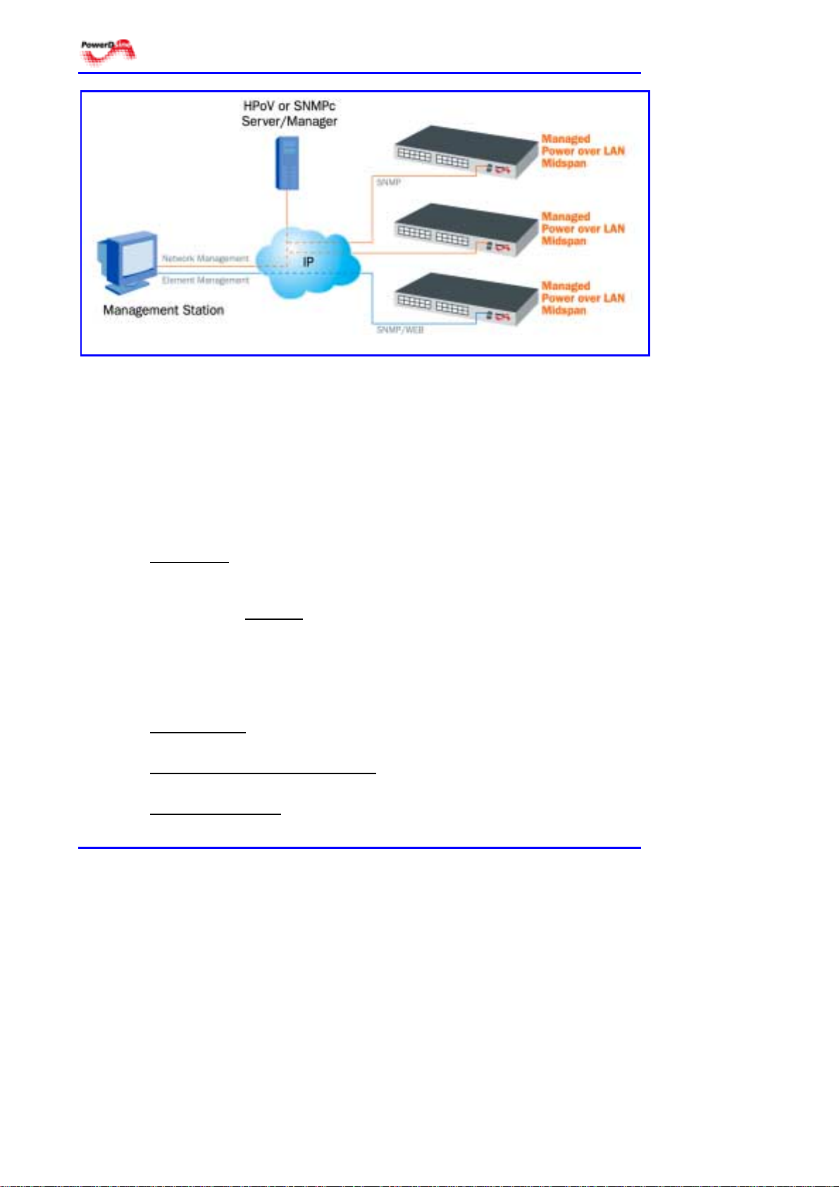
PowerDsine PowerView allows for monitoring and controlling at two separate
levels, as shown in Figure 2-1:
!!!! Network level
!!!! Element level.
Version 2.1 7 March 2003
Page 10
SNMP
Figure 2-1: Management Deployment
2.3.1 Network Level
PowerDsine provides network management capabilities to monitor and control
an array of Power over LAN Midspans. The system is compatible with MIB
management platforms, including HP Openview and SNMPc.
2.3.2 Element Level
Element management is performed at unit and port levels.
At unit level
Midspan. These are: product identification, active power source, product status
and unit power consumption.
Parameters at port level
port status and type of powered device connected.
, parameters can be retrieved directly to the Power over LAN
include: maximum per port power, port priority level,
2.4 Security
Security is implemented in PowerDsine PowerView on three levels:
SNMP security
community field.
User privately-implemented secur ity
of each and every employee.
Password protection
alphanumeric characters long.
Power over LAN Solutions 8 Catalog Number: 06-6910-056
- handles the entire SNMP communication process by the
– The User can specify the access level
– the User is required to enter a password 3 to 10
Page 11

Web Manager User Guide 2. Introducing PowerDsine PowerView
2.4.1 SNMP Security
Community strings provide a basic form of access control in SNMP v2
(PowerDsine PowerView is based on SNMP v2). Whenever a community
string is defined, it must be provided along with any basic SNMP query, if the
requested operation is to be permitted by the device. Community strings
usually allow read-only or read-write access to the entire device. SNMP
community authentication is part of the setup for the server. The authentication
can be changed by the user, via a console and via a Web browser.
In the absence of additional configuration options to constrain access,
knowledge of the single community string for the device is all that is required to
gain access to all objects, both read-only and read-write, and to modify any
read-write objects.
2.4.2 User Authentication
PowerDsine PowerView employs user-type authentication in order to verify the
identity of each user. The authentication is a type/password verification. An
encrypted password is allocated for each user type.
The program has defined several user types for the system. These users have
a different role and, as such, have different access authorizations. Each user
type is allocated a different scope of access control. Access definitions per
user, are listed in Table 2-1.
Table 2-1: User Authorizations
USER TYPE AUTHORIZATION
• Can view relevant parameters of the PoL Midspan.
Operator
Supervisor
Administrator
• Not allowed to change or add new parameters.
• Can view pertinent information on the system, including online alerts.
• May change his password.
• Acts as an operator.
• Can view and edit SNMP MIB2 information.
• Can change the configuration of Units and Ports.
• Acts as a supervisor.
• Can update software .
• Can perform remote system reset
• Change SNMP parameters:
* Community authentication for SNMP agents
* Polling interval
* Polling timeout
* Polling retries
Version 2.1 9 March 2003
Page 12

SNMP
Reader’s Notes
Power over LAN Solutions 10 Catalog Number: 06-6910-056
Page 13

Web Manager User Guide 3. Installation
3 Installation
3.1 System Requirements
The following hardware/software items are required in order to configure and
operate the Power over LAN (PoL) Midspan.
!!!! Computer environment
# Operating system: WIN 98 or WIN 2000 or WIN XP
# Serial ports: COM1 or COM2 are active and available
# Access to a local network and Internet
# Null-modem cable
# Ethernet cable.
!!!! Administrative requirements
# IP address for the PoL Midspan (to be obtained from the network
manager, unless the services of a DHCP server are used)
# Internet browser installed (recommended Explorer 5.0 and higher)
# Verify your computer IP address, using one of the following:
For WIN 98
1. Go to DOS prompt (Start> Programs> MS-DOS Prompt).
2. Type the command: ipconfig, then click Enter.
3. Write down your IP address, your default gateway and the subnet
For WIN 2000 and WIN XP
1. Go to Run (Start> Run).
2. Type cmd. A DOS type window will open; then click OK.
3. Type the command ipconfig, then click Enter.
4. Write down your IP address, your default gateway and the subnet
mask, for future reference.
mask, for future reference.
3.2 Software Installation
3.2.1 CD Contents
PowerDsine PowerView is delivered with a CD that includes a number of
programs:
!!!!
SnmpLocalClient folder – files used to surf the PoL unit locally.
!!!!
javaws-1_0_1_XX-win-int-rt.exe – this is the Java Web Start software.
!!!!
PowerDsine pack n.n – the folder includes a pack of software files for
SNMP capabilities.
Version 2.1 11 March 2003
Page 14
SNMP
3.2.2 Installation
$ Perform the next 3 steps:
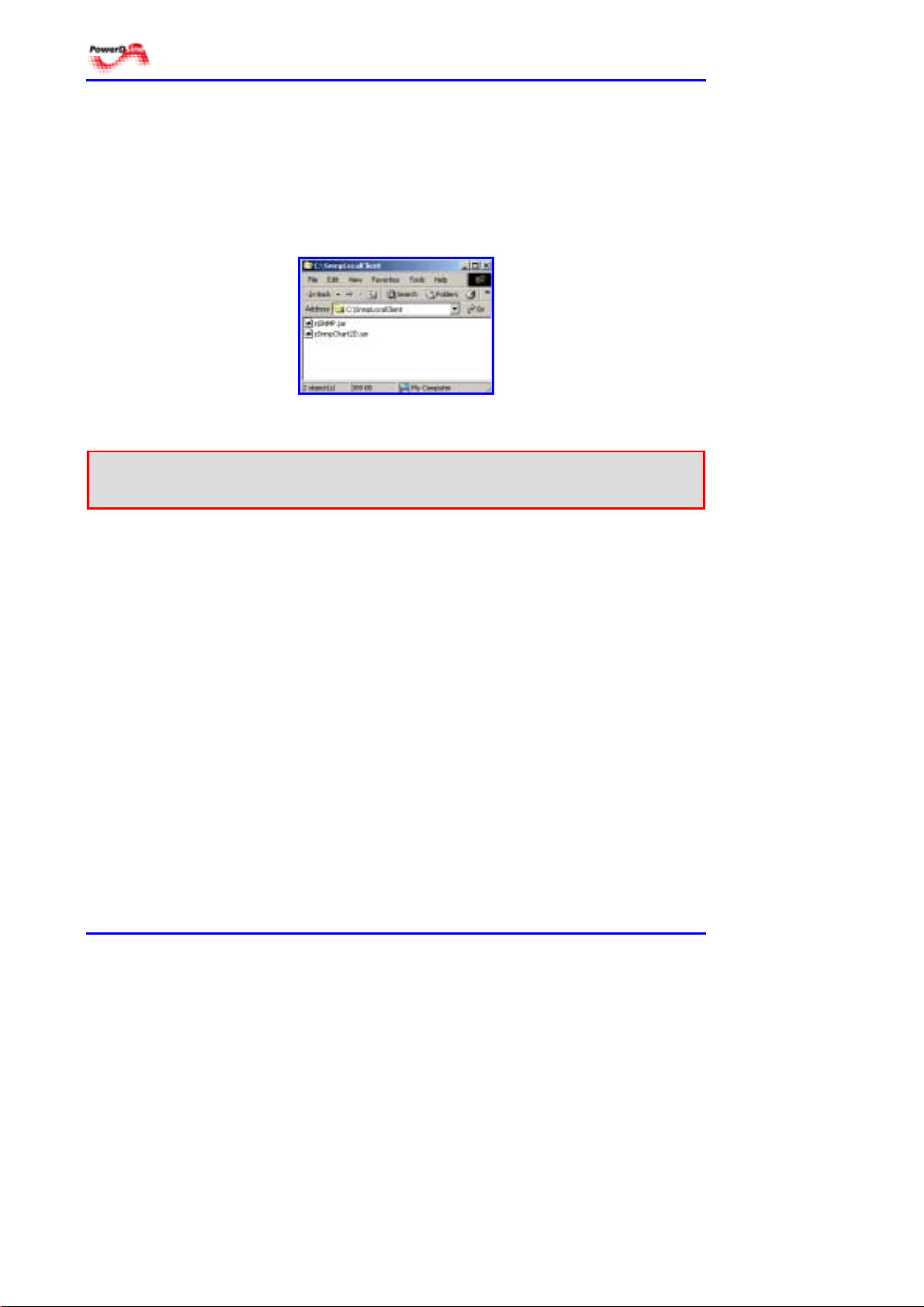
Step 1 From the attached CD, copy the folder SnmpLocalClient to the c:\
drive on your computer (this drive is a must). See Figure 3-1. The
files in this folder contain graphic files that are needed for uploading
the Management GUI, when using the local surfing option.
Figure 3-1: SNMP Local Client Files
Warning! * Do not change the names of the libraries. The program will not function.
* Copy the libraries as folders and not as individual files.
Step 2 The PowerDsine pack n.n provides a software pack for the PoL
Midspan operating system and for the GUI.
Step 3 The javaws-1_0_1_XX-win-int-rt.exe application is installed
according to directions in the program. This file can be installed at
this time or later on. Java Web start provides for the interfacing of
different versions of operating systems, Internet browsers, etc…
3.3 Setting Communication Parameters
The Command Line Interface (CLI) on the PoL unit is used to interconnect with
the user’s computer.
$ Do the next 4 steps to set communication parameters:
Step 1 Click on Start >Program >Accessories >Communications >
HyperTerminal (you may have to double click on the icon
“Hypertrm.exe”). The dialog box shown in Figure 3-2 appears.
Power over LAN Solutions 12 Catalog Number: 06-6910-056
Page 15
Web Manager User Guide 3. Installation
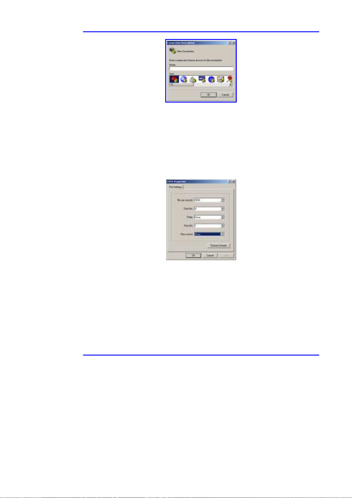
Figure 3-2: HyperTerminal Registration
Step 2 Enter your name or organization name in the Name text field of
Figure 3-1. Then, click on the OK button.
Step 3 In the Connect To window, select on the Connect using drop-
down menu, the communication port to be connected to the PoL
unit. Then, click on the OK button. The dialog window, shown in
Figure 3-3, appears.
Figure 3-3: Selecting Communication Parameters
Step 4 In Figure 3-3, fill in the following parameters:
Bits per second: 9600
Data bits: 8
Parity: None
Stop bits: 1
Flow control: None
Then, click on the OK button.,The HyperTerminal screen appears,
Version 2.1 13 March 2003
Page 16

SNMP
as shown on Figure 3-4.
Figure 3-4: HyperTerminal Screen
3.4 Starting up
Initial programming of the Midspan is automatic, as shown in paragraph 3.4.1,
hereafter. For manual programming, refer to paragraph 3.4.2.
3.4.1 Installation using the DHCP Server
PowerDsine PowerView unit default configuration is DHCP-enabled client
when logging on to the network. When starting up, the PowerView unit
configuration is that entered the last time.
$ Perform the next 5 steps:
Step 1: Connect the PoL unit to AC power and connect the null-modem
cable between the management station COM port and the PoL
RS-232 port. Connect a network cable between the PoL unit front
panel and the LAN. See the test set-up as shown in Figure 3-5.
Step 2: Wait until the command line (pSH0+>) is displayed on the screen.
Step 3: Type in ipconfig. The Midspan unit identification is displayed as:
ipaddress: nnn.nnn.nnn.nnn;
MAC address: nnn.nnn.nnn.nnn
Step 4: Record the two values for future reference.
Step 5: Proceed to paragraph 3.5 page 17, for browsing.
Power over LAN Solutions 14 Catalog Number: 06-6910-056
Page 17
Web Manager User Guide 3. Installation
3.4.2 Network Interface Parameters
The next steps configure the network parameters (on a manual basis), such as
assigning an IP address to the PoL Midspan.
Notes 1. In case that you enter wrong parameter in one of the following steps,
choose (M)odify (press Enter for default), in the following option:
“(M)odify any of this or (C)ontinue? [M]”
2. The order given hereafter may be varied due to the specific operating
system.
$ Perform the next 6 steps:
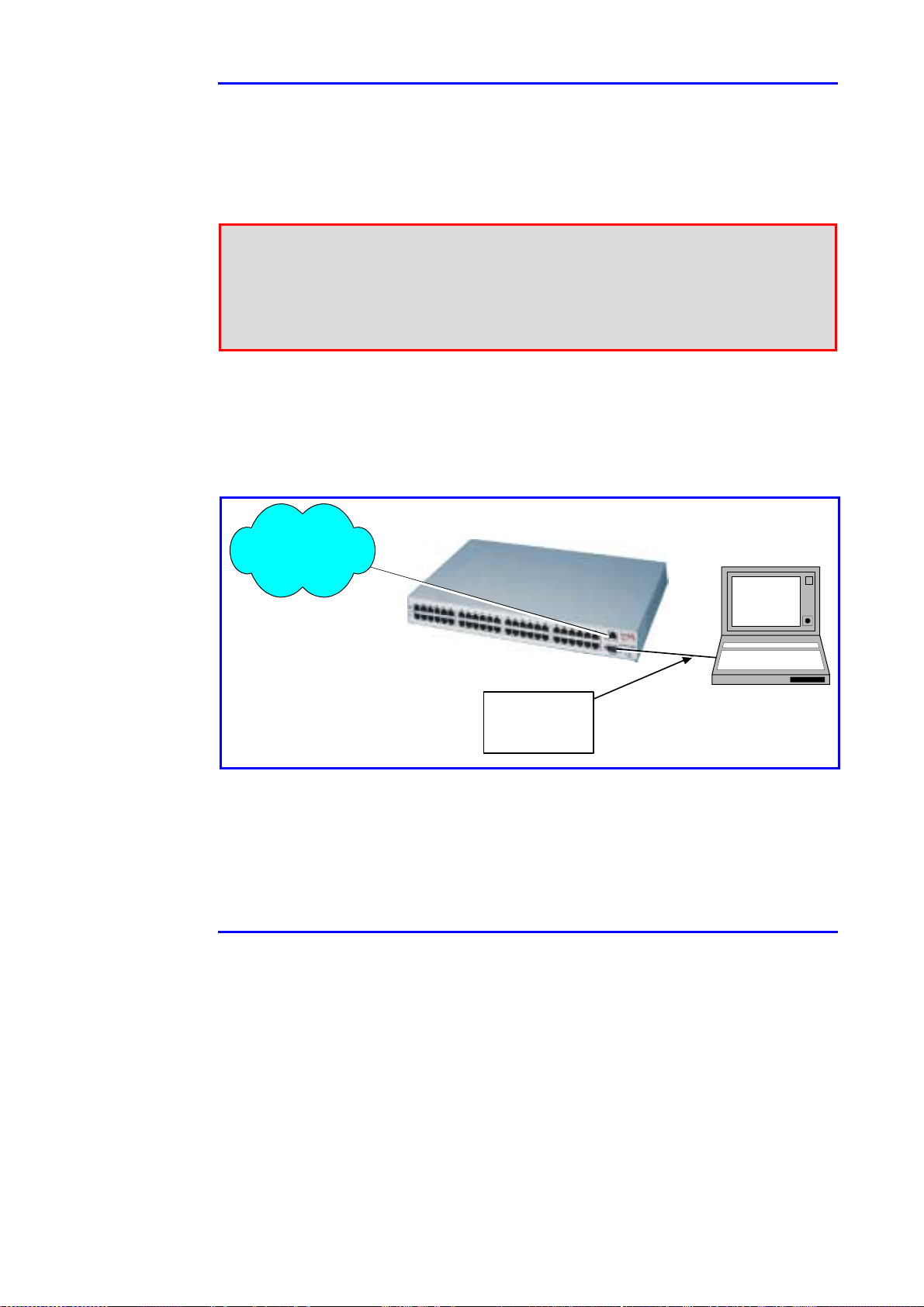
Step 1: Connect the PoL unit to AC power and connect the null-modem
cable between the management station COM port and the PoL
RS-232 port. Connect a network cable between the PoL unit front
panel and the LAN. See the test set-up as shown in Figure 3-5.
PoL Unit
LAN
NULL
MODEM
CABLE
To configure
Network Interface
parameters
Management
Station
Figure 3-5: Connecting the PoL Unit
Step 2: Figure 3-6 appears.
Version 2.1 15 March 2003
Page 18

SNMP
Figure 3-6: Network Parameters Screen
Step 3: Press any key within five seconds.
Step 4: For each of the following questions press Enter to obtain the
default shown in brackets [ ] or you can type a new value:
“Do you want to obtain LAN IP address from DHCP?
[Y]”
“LAN IP address (0.0.0.0)? [168.0.0.1
]“
Type the IP number of the unit, which you have received from your IT
manager, separated with dots.
For example: nnn.nnn.nnn.nnn
“Subnet mask (0.0.0.0)? [255.255.0.0
]“
Enter subnet mask.
“Default gateway IP address (0.0.0.0 for none)?[0.0.0.0
]“
Enter your default gateway.
“How long (in seconds) should CPU delay before starting
up? [5]”
(M)odify any of this or (C)ontinue? [M] C
Step 5: Define the TFTP server to be used for future unit software upgrade.
“To change any of this, press any key within 2
seconds”
Press any key within two seconds.
Power over LAN Solutions 16 Catalog Number: 06-6910-056
Page 19

Web Manager User Guide 3. Installation
In the sentence “IP address of the TFTP host is?
[127.0.0.1]” type the IP number of the computer used as a
TFTP server.
Name of the file to load and? [ram.hex]
Click Enter.
Do you wish to load a new software version? [N]
Click N or Enter to continue. Click Y to update the software.
3.5 Browsing
To surf to the PoL Midspan, the browser is used. There is a need for Java
files, in order to run the GUI on the Management Station. These Java files can
be retrieved from one of two possible sources:
1. Local – from the Management Station
2. Remote – from PowerDsine’s Web site, located in the USA.
The user may select to perform the steps of either paragraph 3.5.1 or 3.5.2,
but not both. If a Java Web Start Security Warning window comes up,
click on Start.
3.5.1 Local Surfing
$ Perform the next 7 steps:
Step 1 At this time, the null-modem cable between the computer and the
PoL unit, may be disconnected.
Step 2 Connect the RJ-45 Ethernet cable between the PoL unit and the
local area network (see Figure 3-5).
Step 3 Open your Internet browser, then go to link: http:// [IP number],
where IP number is the Power over LAN (PoL) unit IP designation
you received from your IT manager, for the PoL Midspan (refer to
step 4, paragraph 3.4.1), unless you are using the services of a
DHCP server.
For example: http:// nnn.nnn.nnn.nnn
Step 4 Click on the following link LOCAL Web Management System (see
Figure 3-7).
Figure 3-7: Local Link
Version 2.1 17 March 2003
Page 20

SNMP
Step 5 Wait few seconds while the Java Web Start loads the plug-ins (see
Figure 3-8).
Figure 3-8: Java Web Start
Step 6 When the dialog box shown in Figure 3-9 appears, type, in the
Password field: admin.
Step 7 In the Address field the unit’s IP number appears. Then click on
the OK button, to open the Main Navigation menu GUI window.
Figure 3-9: Log in Screen
3.5.2 Remote LAN Web Management System
$ Perform the next 7 steps:
Step 1 At this time, the null-modem cable between the computer and the
PoL unit, may be disconnected.
Step 2 Connect the RJ-45 Ethernet cable between the PoL unit and an
entreprise network, having Internet access (see Figure 3-5).
Step 3 Open your Internet browser, then go to link: http:// [IP number],
where IP number is the Power over LAN (PoL) unit IP designation
you received from your IT manager, for the PoL Midspan (refer to
step 4, paragraph 3.4.1) unless you are using the services of a
DHCP server.
For example: http:// nnn.nnn.nnn.nnn
Step 4 Click left mouse button on the following link Remote Web
Management System (see Figure 3-10).
Power over LAN Solutions 18 Catalog Number: 06-6910-056
Page 21

Web Manager User Guide 3. Installation
Figure 3-10: Remote Link
Step 5 Wait few seconds while the Java Web Start loads the plug-ins (see
Figure 3-8).
Step 6 When the dialog box shown in Figure 3-9 appears, type, in the
Password field: admin.
Step 7 In the Address field the unit’s IP number appears. Then click on
the OK button, to open the Main menu GUI window.
3.6 TFTP Server Configuration
The TFTP server stores the programs used by the PoL unit (refer to Section 6,
page 49). The next paragraph describes how to configure the TFTP server for
software update. This procedure is optional and needs to be done when
upgrading the unit’s software.
Notes 1. The TFTP software is not included in the CD provided with the Midspan.
2. Any TFTP server program may be used for software update.
3. Make sure that the computer used as a server is always on.
4. Make sure that the TFTP server software is running.
$ Perform the next 6 steps:
Step 1 Set-up a computer to act as a server. Make certain that this
computer is accessible by all PoL Midspan users.
Step 2 If you have not done so, copy the PowerDsine pack n.n to the c:\
drive (only) of the computer acting as a server.
Step 3 Open the TFTP software, installed on disk c:\. The window shown
in Figure 3-11 appears. In the field Server Interfaces, the
computer’s IP address is given.
Step 4 In the TFTP window, click on the Settings button.
Version 2.1 19 March 2003
Page 22

SNMP
Figure 3-11: Opening the TFTP Window
Step 5 In the base directory, shown in Figure 3-12, click on the Browse
button and select the PowerDsine pack n.n that you copied to
your C drive.
Step 6 Click Ok when done.
Figure 3-12: Base Directory Settings
Power over LAN Solutions 20 Catalog Number: 06-6910-056
Page 23

Web Manager User Guide 4. Managing with PowerDsine PowerView
4 Managing with PowerDsine PowerView
4.1 GUI Description
4.1.1 Overview
The GUI (Graphic User Interface) provides for complete monitoring, control and
configuration of PowerDsine’s Power over Line (PoL) products, via their SNMP
agents. This is done in an easy way, offering graphical representations of the
actual device in addition to information tables. The system provides several
views:
!!!! Graphical view of the device monitored
!!!! Alarms/notification table for the device being monitored
!!!! Properties of the management system.
The GUI authorizes program access options to management users, according to
their passwords. The system administrator carries highest privileges, followed by
the supervisor. The operator has lowest privileges. In order to log in and work
with the GUI, the installation process, described in Section 3, must have been
performed in its entirety.
4.2 Logging in
PowerDsine PowerView manages a single unit at a time. More than one unit can
be managed using standard management platforms, such as: HP Openview,
SNMPc and similar platforms.
4.2.1 Logging in
$ Perform the next 4 steps:
Step 1 Open your web browser and type the IP Address of the PoL unit to
be managed.
Step 2 On the Log-in screen, type the IP address of the unit in the Address
field and the password in the Password field.
Step 3 Click on the User Category pulldown menu (see Figure 4-1), to select
one of the following user authentication options available:
1. Administrator
2. Supervisor
3. Operator
Figure 4-1: Selecting User Category
Version 2.1 21 March 2003
Page 24

SNMP
Note Address: the IP address of the SNMP agent of the specific management
card controlling the PoL unit.
User Type: the function performed by the managing user, selecting one of
three options offered by the system.
Password: alphanumeric string, minimum three characters to be entered by
the user, shown on the screen as asterisks (***).
Step 4 The final step is to click on the OK button; this can cause one of two
results:
1. Successful entry to the system; in this case the screen shown in
Figure 4-2 will appear. This is the Main Navigation window.
2. Unsuccessful entry; the system will return with one of the
following messages:
* Incorrect password
* General server failure, including an error code number.
Note Three unsuccessful trials to log in will cause the application to close.
Figure 4-2: Main Navigation Window
Power over LAN Solutions 22 Catalog Number: 06-6910-056
Page 25

Web Manager User Guide 4. Managing with PowerDsine PowerView
4.3 Opening Screen
The Main Navigation window (shown in Figure 4-2), is detailed in Figure 4-3.
Figure 4-3: Defining Main Navigation Window
!!!! Menu bar - provides for selection of major tasks:
# System – used for program related functions, such as program
updates, refreshing data from the device and exiting the PowerDsine
PowerView program.
# Device – all items under this task, are related to the device shown in
the display window.
# Port – all entries in this task are related to the ports being powered by
the unit.
!!!! Status Labels – two labels appear on the window:
# Unit identification – allocated at factory
# User category - defined by the logging in process (para. 4.2.1)
!!!! Tabulation – there are several tabs which appear on a permanent basis at
the bottom of the window; each tab allows a different page to pop-up. To
move to that page, click the tab:
# Map – In this area are displayed the two entities being managed.
# Properties – this tab is restricted to administrators. The corresponding
display provides a list of parameters, specific to the unit selected.
# Traps Log – displays all traps for all units in the system.
Version 2.1 23 March 2003
Page 26
SNMP
# Command Log – displays all network events.
# Selected Device – shows a visual representation of the device
targeted in the map area. The display is active as it identifies port
status and operational parameters.
# Other tabs come up during operation. These tabs can remain on the
screen or can be removed, by exiting the related panel.
!!!! Main display area – for tabular lists or graphical representation of unit.
4.4 Basic Navigation
4.4.1 Fields
The Main Navigation window includes a number of items, used to navigate
through the program:
Text fields – these are white rectangles where a name or title is typed. Click the
field to put the text insertion point there and then type the entry.
Drop-down menus – are used when one option must be selected from a list of
possibilities.They look like text fields with a down-arrow at the right end. To use
a drop-down menu, click the down-arrow. A list of possible entries will appear.
Click on the required entry.
Buttons – these are raised areas with text on them. The most common are OK
and YES/NO.
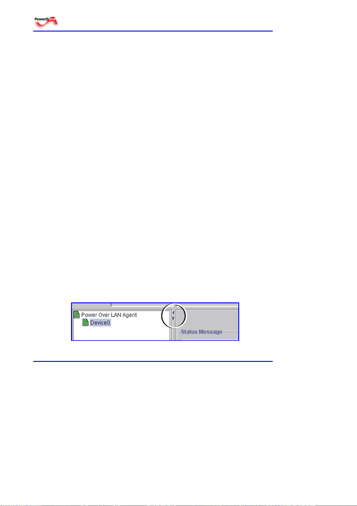
4.4.2 Controls
4.4.2.1 Controlling display size
There are several possibilities to expand/reduce the working areas on the Main
Navigation window. Some are standard WINDOWS features, such as grabbing
one of the edges and dragging it to change the proportions. In particular, there
are two arrows which are used for changing the size of the main working areas
(see Figure 4-4).
Figure 4-4: Changing the Work Area Size
Power over LAN Solutions 24 Catalog Number: 06-6910-056
Page 27

Web Manager User Guide 4. Managing with PowerDsine PowerView
Clicking on one of these arrows, deletes one of the Main Navigation window
areas and expands the other. To return to the former split display, click the
enlarge button at the top right of the Main Navigation window.
4.4.2.2 General display commands
The various tabs, carry along different commands, depending on the particular
tab. These commands are illustrated below (Figure 4-5).
Figure 4-5: Commands Possibilities
Copy – used to copy a list of traps to the Windows clipboard. A trap file consists
of several messages.
Refresh – updates the information from the SNMP.
Clear – erases all messages in the trap file.
Set – saves last updates of parameters.
Exit – terminates the current screen (tab).
Graph – provides a graphical representation of selected power parameters.
4.4.3 Port Level
The PoL ports are located on the top row of the selected device panel. The
bottom row in the panel is used to carry data. Individual ports can be activated
or disabled, by pointing and double-clicking on the graphical representation of
that port(s). By doing so, a pop-up menu appears on the window. When the port
is enabled, the indication is in yellow; with the port disabled, the representation is
in black.
4.4.4 Visual Indications
The graphical display panel includes a number of visual indicators for operating
power input and output ports.
4.4.4.1 Power indications
Two LEDs on the front panel, marked by “AC” and “DC”, provide the Power over
LAN Midspan power status. When either one of the indicators is illuminated in
green, the Power over LAN Midspan is receiving AC or DC power. The “AC” and
“DC” indicators are lit in orange to indicate an internal fault. Refer to Table 4-1
for additional information.
Version 2.1 25 March 2003
Page 28

SNMP
4.4.4.2 Port status
One bi-color indicator (green and orange), per port, provides port status:
!!!! Green indicates that the terminal unit has been identified as "Power over
LAN Enabled" and is active and receiving power.
!!!! Orange indicates that the port is not supplying power and is not active.
Refer to Table 4-1 for additional information.
Note Due to the standard detection process performed on each PoL port, power
will not be supplied to an Ethernet device, that is not PoL-enabled (indicated
in orange or off). In this way, Ethernet devices (not PoL-enabled) will not be
affected by this connection.
Table 4-1: Main Power Status Indications
INDICATOR COLOR
Off
AC
Green
Green
blinking
Off
DC
Green
Green
blinking
AC and DC
Orange
MAIN POWER
STATUS
Internal power
supply unit is
unplugged or
faulty.
Indicates AC power
input active.
Internal power
supply voltage is
out of tolerance.
No DC input power
available.
Indicates DC
power input active.
DC Input voltage is
out of tolerance.
Internal problem
alarm.
REMARKS
Internal power supply voltage is
too low. All ports are
disconnected.
Internal power supply voltage is
within tolerance.
All ports are disconnected.
DC input voltage is too low. All
ports are disconnected.
DC input voltage is within
tolerance.
All ports are disconnected.
Built in Test (BIT) failed.
Power over LAN Solutions 26 Catalog Number: 06-6910-056
Page 29

Web Manager User Guide 4. Managing with PowerDsine PowerView
Table 4-2: Port Status Indications
Port LED Color Port Load Conditions Port Voltage
Off
Green
Orange
Green blinking
Orange blinking
Non-active load or
unplugged port.
Active load is plugged in
and complies with normal
load conditions.
Overload conditions; or
short; or forced external
voltage feed (constant
DC) into the port.
Transitional mode in
which load detection is in
process or discharged
capacitor in the PD.
Total aggregated power
exceeds pre-defined
power budget.
Power to the port is disconnected.No
DC voltage present on spare pairs.
Continuous nominal DC voltage is
present on the spare pairs.
Power to the port is disconnected.
No DC voltage is present on the spare
pairs.
Power to the port is disconnected.
No DC voltage is present on the spare
pairs.
Power to the port is disconnected.
No DC voltage is present on the spare
pairs.
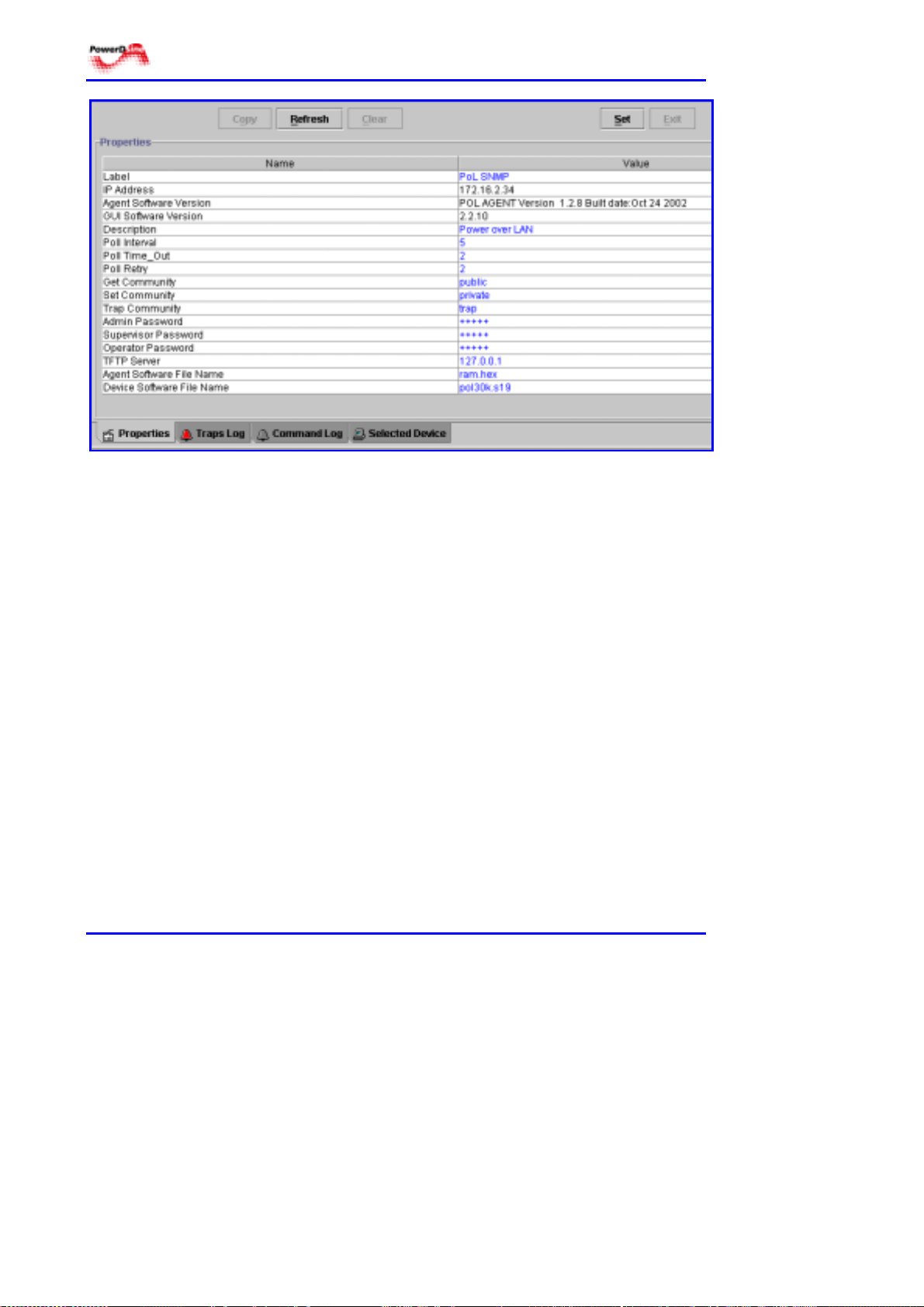
4.5 Properties Definition
4.5.1 General Guidelines
The properties panel (see Figure 4-6) may be accessed by all categories, but
may be updated only by administrators. To access, click on the Properties tab
at the bottom of the Main Navigation window. In this panel, general guidelines
are followed to modify parameters. These guidelines are:
!!!!
Fields which can be edited are in blue.
!!!!
Fields which are being edited are in red.
!!!!
Field which cannot be modified are in black.
!!!! To edit a field:
# Double click on that field
# Change the text
# Save the changes by clicking on the Set button.
!!!!
It is possible to revert to previous data, when displayed in red, by clicking
on the Refresh button.
Version 2.1 27 March 2003
Page 30
SNMP
Figure 4-6: Properties Panel
4.5.2 Definitions
Label: name of the SNMP device (maximum string length is 15 characters)
IP Address: IP address of the SNMP device
Agent Software Version: software version of agent
GUI Software Version: software version of GUI
Description: user-definable text (maximum string length is 50 characters)
Poll Interval: time parameter, defines the time (in seconds) between
consecutive polling actions done by the network manager. Values are:
Default: 5 s
Minimum: 1 s
Maximum: 50 s
Poll Time_Out: time parameter, defines the maximum time (in seconds) the
network manager is to wait for the results of his polling. After this time, if no
information was received from the agent, a new polling is activated. Values are:
Default: 2 s
Minimum: 1 s
Maximum: 100 s
Power over LAN Solutions 28 Catalog Number: 06-6910-056
Page 31

Web Manager User Guide 4. Managing with PowerDsine PowerView
Poll Retry: defines the number of pollings done after no information was
received from the network agent for the first polling. Values are:
Default: 3 s
Minimum: 1 s
Maximum: 100 s
Note The user should define timing parameters in a way to keep with the
following rule: (polling retries x poll timeout) < polling interval.
Get Community: name for those who have the permission to retrieve
information or to monitor network agents (maximum string length is ten
characters).
Set Community: name for those who have the permission to edit different
parameters of network agents (maximum string length is ten characters).
Trap Community: name for those who have the permission to receive traps
from network agents (maximum string length is ten characters).
Admin Password/Supervisor Password/Operator Password: alphanumeric
string (10 characters maximum). Applies respectively to Administrator,
Supervisor and Operator.
Note Network communities and the password strings are case sensitive.
TFTP Server: defines the IP address of the TFTP server used for software
downloads.
Agent Software File Name: the name of the SNMP-based management
software file to be downloaded (maximum string length is 10 characters).
Device Software File Name: the name of the device software file to be
downloaded. A line per each device will be available in the properties table, to
enable downloading different software files to each device (maximum string
length is 10 characters).
4.5.3 Commands
Refresh: reverts to previous data, marked in red.
Set: saves the new data entered.
Version 2.1 29 March 2003
Page 32

SNMP
4.6 Viewing Trap Log Entries
4.6.1 About Traps Recording
PowerDsine PowerView includes an internal SNMP trap handler which records
SNMP traps addressed to it. A trap is sent when the status of a device changes.
Traps are unsolicited messages, such as a port sensing its PD was
disconnected or main AC power switching to standby (DC power source).
Figure 4-7 displays a number of traps recorded by the application program. The
individual trap listings compose a file started the moment PowerDsine
PowerView initates the connection between the PoL unit agent and the SNMP
manager. File content is limited to 5000 messages.
Once the connection is terminated, this log file is erased. The operator can
choose to copy the file at any time.
Note Communication problems of the managed device with the manager will be
indicated by Red error messages.
Figure 4-7: Trap Log Panel
4.6.2 Definitions
Date: the day and time the message was received from the agent and logged.
Node: describes the IP address of the device reporting the message.
Type: message type, based on the Power Ethernet MIBs.
Power over LAN Solutions 30 Catalog Number: 06-6910-056
Page 33

Web Manager User Guide 4. Managing with PowerDsine PowerView
Message: text defining the message sent from the agent.
The different columns in the table can be adjusted in order to view the full
description.
4.6.3 Commands
Copy: clicking on this button will copy the file to the Windows clipboard.
Clear: this operation will erase all messages in the file displayed.
4.6.4 Types of Traps
There are three types of SNMP traps which are used and displayed:
!!!! Standard traps
!!!! Standard Power over Ethernet
!!!! Private PoL
The various traps are listed hereafter.
4.6.4.1 Standard traps
coldStart - a coldStart trap signifies that the SNMPv2 entity, acting in an agent
role, is reinitializing itself and that its configuration may have been altered.
authenticationFailure -an authenticationFailure trap signifies that the SNMPv2
entity, acting in an agent role, has received a protocol message that is not
properly authenticated.
4.6.4.2 Standard Power over Ethernet traps
pethPsePortOnOffTrap - indicates if PSE port is delivering or not delivering
power to the PD.
pethPsePortCurrentStatusTrap - indicates port change status; sent on every
status change.
pethMainPseBackUpActivatedTrap - indicates back-up power is activated or
released.
pethMainPowerUsageOnTrap - indicates PSE threshold usage indication is on
and that consumed power is above the threshold.
pethMainPowerUsageOffTrap - indicates PSE threshold usage indication off
and that consumed power is below the threshold..
Version 2.1 31 March 2003
Page 34

SNMP
4.6.4.3 Private PoL traps
polDeviceDownloadStartTrap - indicates that a download was started for the
device.
PolDeviceDownloadCompleteTrap - indicates that a download was completed
for the device.
polDeviceDownloadFaildTrap - indicates a download failure for the device.
polDeviceGeneralTrap - indicates a general message from the device.
polWWWDownloadStartTrap - indicates a download start from the W WW site.
polWWWDownloadCompleteTrap - indicates that a download was completed for
the WWW site.
polWWWDownloadFaildTrap - indicates a download failure from the WWW site.
polSystemDownloadStartTrap - indicates a download start for System (agent).
polportVoltageStatusTrap - indicates a port change status; sent on every voltage
change.
4.7 System Menu
4.7.1 About the System Menu
The System Menu is a top-level set of commands used mainly for downloading
programs (see Figure 4-8). For details on the download process and
methodology, refer to section 6, Software Upgrading, on page 49.
Note Programs can be downloaded only by the administrator.
4.7.2 Definitions
Caution
Downloading a program will cause a break in communications between the
PoL Midspan and its SNMP card. The icons on the left-hand side of the Main
Navigation window, switch from green to red, then back to green.
Simultaneously, all ports will be disabled briefly.
Power over LAN Solutions 32 Catalog Number: 06-6910-056
Page 35

Web Manager User Guide 4. Managing with PowerDsine PowerView
Agent_sw Update: retrieves data from the PoL Midspan to be used by the GUI.
When clicking on this entry, a query dialog box is opened, to ascertain that the
download process is really required. Communication traps are generated when
communications stop and when they return.
GUI_sw update: starts a download process to update the GUI software. When
clicking on this entry, a query dialog box is opened, to ascertain that the
download process is really required. Communication traps are generated when
communications stop and when they return.
Refresh: updates the information received from the device selected.
Save Configuration: allows saving of the configuration in the managed device.
Restore Default Parameters: enables to restore all parameters to factory
defaults.
Exit: terminates program connection.
Figure 4-8: System Menu
4.8 Device Menu
4.8.1 About the Device Menu
The Device menu provides the user with means to configure the device. Most of
the available functions are reserved for Supervisor and/or Administrator level
(see Figure 4-9).
4.8.2 Definitions
Reset (for supervisor and administrator only): activates a reset operation on the
device chosen. When clicking on this entry, a query dialog box is opened, to
ascertain that the reset is really required. Communication traps are generated
for the boot.
Version 2.1 33 March 2003
Page 36

SNMP
Device_sw Update (for administrator only): starts the software download
process for the Power over LAN Midspan. W hen clicking on this entry, a query
dialog box is opened, to ascertain that the download is really required.
Communication traps are generated for the start and stop of the download.
For details on the Device software download process and methodology, refer to
section 6, Software Upgrading, on page 49.
Figure 4-9: Device Menu
Power Enable and Power Disable (for supervisor and administrator only):
enables or disables all ports in one action. When clicking on this entry, a query
dialog box is opened, to ascertain that the disable/enabling process is really
required. Once the ports are disabled, the device graphical representation is
displayed and all output ports are shown in black (disabled).
Trap Enable and Trap Disable (for supervisor and administrator only): enables
or disables traps from the selected device. When clicking on this entry, a query
dialog box is opened, to ascertain that the disable/enabling process is really
required.
Product Information (for supervisor and administrator only): clicking on this
entry opens a corresponding panel (see Figure 4-6) with the information on the
device, as described hereafter.
In this panel, general guidelines are followed to modify parameters. These
guidelines are:
!!!!
Fields which can be edited are in blue.
!!!!
Fields which are being edited are in red.
!!!!
Field which cannot be modified are in black.
!!!! To edit a field:
# Double click on that field
Power over LAN Solutions 34 Catalog Number: 06-6910-056
Page 37

Web Manager User Guide 4. Managing with PowerDsine PowerView
# Change the text
# Save the changes by clicking on the Set button.
!!!!
It is possible to revert to previous data, when displayed in red, by clicking
on the Refresh button.
Product Info panel entries are detailed herafter:
Device Name: string defined by user (limited to 10 characters). Can be changed
only from an MIB browser.
Device Software Version : defines the device’s software version and release
date.
Device Boot Software Version : defines the version of boot software and the
date of release.
Serial Number : the factory serial number of this specific device.
Device Hardware Version : number identifying the device hardware version.
Part Number : product part number, according to the device type.
PD Detection Method : IEEE (resistor), or both IEEE (resistor) and PowerDsine
(capacitor). Clicking on this field creates a drop-down menu (see Figure 4-10).
Default is both.
Figure 4-10: Selecting the Interrogation Method
Power Parameters (for supervisor and administrator only): clicking on this entry
opens a corresponding panel (see Figure 4-11) with the power parameters
information, as described hereafter:
Total Available Power [Watt]: main total power of the device (200 W).
Power Consumption [Watt]: total power consumed by the device.
Current Consumption [mA]: total current consumed by the device.
AC Input Voltage Status: status of the incoming voltage, if it is within the
specified range. Three states are available:
# Normal (voltage within range)
# Fault (voltage not within range)
# Off (main voltage is not connected).
Version 2.1 35 March 2003
Page 38

SNMP
Figure 4-11: Power Parameters Panel
Power Backup Present: status of the DC backup connection. There are 3
possibilities:
# On (backup is connected, within range)
# Fault (backup is connected, not in range)
# Off (backup is not connected).
Backup Activated: shows whether the device is using the backup source. Two
states available: Activated, Not activated.
Backup DC Voltage [Volt]: DC voltage created when the device is powered from
a DC source.
Usage Threshold [%]: shows the quantity of power used as part of the maximum
allowed. When this threshold is passed a trap is sent to the network manager.
Note Two different maximum values are used, one when the main AC supply is
used, the other when the DC backup is used. Values are:
Default: 80%
Minimum: 10%
Maximum: 99%
Power over LAN Solutions 36 Catalog Number: 06-6910-056
Page 39

Web Manager User Guide 4. Managing with PowerDsine PowerView
Maximum DC Power [Watt]: defined by the user, describes the maximum
available power to be supplied by the DC backup source to this device.
Restricted between 36 to 500 W.
Note When opening this table, a special 5-second refresh is activated, unrelated to
the general polling parameters.
4.8.3 Commands
Refresh: restores previous parameters, before the Set operation.
Set: saves last parameters update.
Exit: terminates this panel and returns to Selected Device panel.
Graph: clicking on this button brings the graphical representation of one of the
two (or both) parameters chosen in the graph column. These two parameters
are:
!!!! Total Power Consumption (W)
!!!! Main Current Consumption (mA)
$ Perform the next 3 steps, to obtain one or both graphs:
Step 1 Position the cursor over the desired parameter, in the Graph column.
Step 2 Click on the location selected to obtain a pull-down window (see
Figure 4-12).
Figure 4-12: Graph Request
Step 3 Click on the desired statement (true to obtain a graphical
representation). The appropriate graphs appear (see Figure 4-13).
Figure 4-13: Graphical Representation of Power Parameters
Version 2.1 37 March 2003
Page 40

SNMP
4.9 Port Menu
4.9.1 About the Port Menu
The Port menu (shown in Figure 4-14) allows the user to control individual ports,
monitor their status, and set-up parameters. Specifically, via this menu, the user
can:
!!!! Activate/shut-down individual ports.
!!!! Allocate power per port
!!!! Set-up the priority of each port
!!!! Monitor the status of individual ports
!!!! Obtain actual current drawn at each port
!!!! Establish the type of power device (PD) connected to each port
Note All change-of-state commands are done only by administrator or supervisor.
Figure 4-14: Port Menu
4.9.2 Commands
Commands vary according to the entry selected in the menu. The commands
are:
Refresh: reverts to previous data.
Set: saves the new data entered.
Exit: terminates this panel and returns to Selected Device panel.
Power over LAN Solutions 38 Catalog Number: 06-6910-056
Page 41

Web Manager User Guide 4. Managing with PowerDsine PowerView
In these panels, general guidelines are followed to modify parameters. These
guidelines are:
!!!!
Fields which can be edited are in blue.
!!!!
Fields which are being edited are in red.
!!!!
Field which cannot be modified are in black.
!!!! To edit a field:
# Double click on that field
# Change the text (either by entering a new value or selecting one of the
possibilities from a pull-down window)
# Save the changes by clicking on the Set button.
!!!!
It is possible to revert to previous data, when displayed in red, by clicking
on the Refresh button.
!!!! The up/down arrows can be used to scroll through the tables in the panels.
4.9.3 Accessing Port Screens
Each port process is accessed via an individual screen, with each screen
including the number of ports in the Midspan device.
4.9.3.1 Power Activation
This table helps the user to monitor and/or activate the ports according to actual
requirements. Each port can be switched to Enable or Disable. The related
panel is shown in Figure 4-15.
To activate/deactivate a port. Move the cursor to the
desired entry, under Value, and follow the General
Guidelines provided in paragraph 4.9.2, above (to edit a
field).
If the value selected is not within the limits, an error message will appear on the
screen and the new entry will not be accepted.
Version 2.1 39 March 2003
Page 42

SNMP
Figure 4-15: Activate/Shut-down Panel
4.9.3.2 Maximum Power
This panel (see Figure 4-16) gives the user the capability to define the maximum
allowed power, per port:
Default: 18 W
Minimum: 1 W
Maximum: 18 W
4.9.3.3 Priority
This table enables to assign priorities to the ports in case the Midspan device is
operating with a limited source of power. There are three available priority
states:
!!!! Critical
!!!! High
!!!! Low.
The Midspan unit will allocate all available power to the PDs, according to the
PoL ports sequential number. Once this power consumption is exceeded, the
unit will enter its Power Management mode. Under this mode, ports having a
higher priority will provide power to their respective PDs.
Power over LAN Solutions 40 Catalog Number: 06-6910-056
Page 43

Web Manager User Guide 4. Managing with PowerDsine PowerView
Figure 4-16: Allocating Power to each Port
4.9.3.4 Detection Status
Note W hen opening this table, a special 5-second refresh is activated, unrelated
to the general polling parameters.
The PowerDsine PowerView application continuously polls each port of the
Midspan device. The results are displayed as either a status or as a fault error
indication (see Figure 4-17).
The options are:
!!!! Detection status:
# Disabled
# Searching
# Detected
# Delivering power
# Fault = Error description
# Invalid PD (powered device)
# Test
# Deny Low priority
Version 2.1 41 March 2003
Page 44

SNMP
!!!! Fault error descriptions:
# VoltTooHigh (port output is above permissible voltage)
# VoltTooLow (port output is below acceptable voltage)
# portNotActive
# hardwareError (unit internal fault)
# overLoadAndUnderLoad (PD goes to over, then under voltage and is
disabled)
# underLoad (PD was disconnected)
# overload (PD consumption is over the limit)
# hardwareCommandError (internal port fault)
# voltFeed (PD presents over 30 V output to unit; orange LED blinks)
# voltFeedAfterDiode (can occur when PD connected to port is
capacitor-detection type and has a charged capacitor in its front-end;
green LED blinks; to fix this problem, disconnect the PD for a while)
# disChargeLoad (PD presents voltage under 30 V; orange LED blinks)
# HighImpedance (impedance over 500 kΩ at port)
# NotRes (unit is set to detect resistor in PD, but some other element is
present at port)
Figure 4-17: Port Status Panel
Power over LAN Solutions 42 Catalog Number: 06-6910-056
Page 45
Web Manager User Guide 4. Managing with PowerDsine PowerView
4.9.3.5 Port Information
This panel shows the status of the ports. The Value field presents two options:
Over current and Under current. The Clear button will send a message to the
agent, to clear this event.
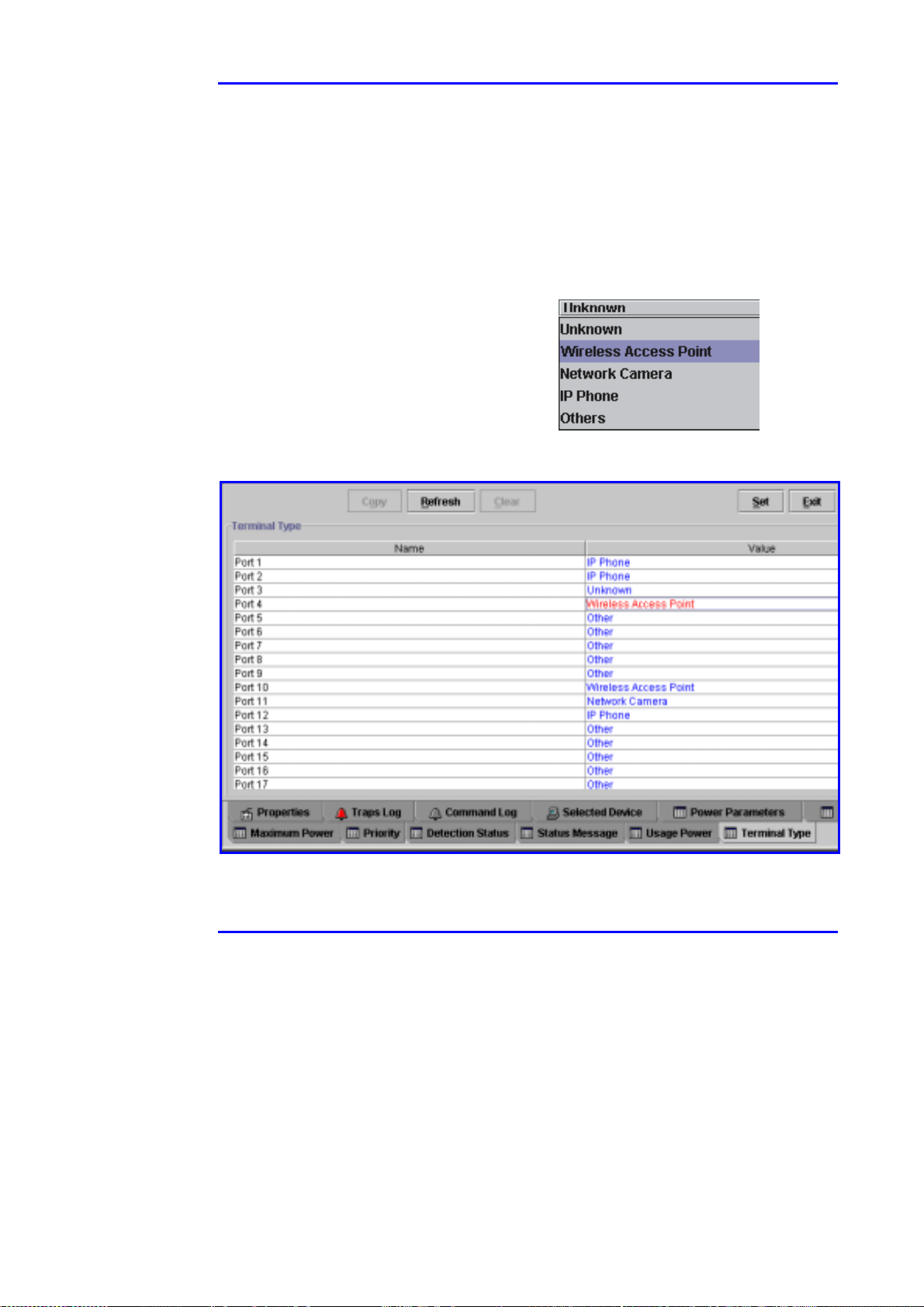
4.9.3.6 Terminal Type
This panel (see Figure 4-18) helps the user to keep his network organized by
recording the type of device being fed by the Midspan device. Five userdefinable options are available:
!!!! Unknown
!!!! Wireless Access Point
!!!! Network Camera
!!!! IP Phone
!!!! Others.
Figure 4-18: Powered Devices Connected to the Midspan
Version 2.1 43 March 2003
Page 46
SNMP
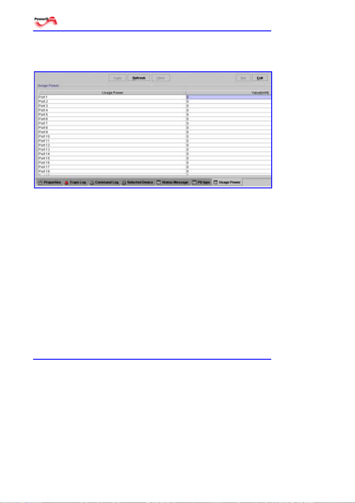
4.9.3.7 Power Consumption
This panel lists the actual power (in mW ) being supplied to each port (see
Figure 4-19).
Figure 4-19: Actual Power Delivered per Port
4.9.3.8 Port Description
In this panel, the operator can enter free text, such as: terminal location, name
of user, his telephone, etc…
Power over LAN Solutions 44 Catalog Number: 06-6910-056
Page 47

p
ping
p
p
Web Manager User Guide 5. CLI Commands
5 CLI Commands
5.1 Built in Capabilities
Using PowerDsine PowerView, it is possible to configure the unit via RS-232
or via Telnet protocol. The CLI commands are used to allocate authorizations
and set up communication parameters. The commands can be activated by
one of two possibilities:
!!!!
Hyper-terminal
!!!!
Telnet protocol - using the network connector (RJ-45) on the Midspan device
It is not possible to configure other parameters, using the CLI commands; the
GUI is designed for this purpose (refer to Section 4, on page 21).
5.2 Commands
Hyper-terminal commands
Refer to Section 3, paragraph 3.4, on page 14, for transferring Hyper-terminal
commands, via the RS-232 port.
- using the DB-9 (RS-232) connector on the Midspan device
Telnet commands
There are two types of Command Line Interface (CLI) which use Telnet types
of commands:
!!!! Standard Telnet protocol commands
!!!! Specially established commands for the PowerDsine PowerView
application.
5.2.1 Opening Telnet Session
To open a Telnet session, refer to paragraph 3.1, page 11.
1. Select the operating system and perform step 1.
2. Type telnet nnn.nn/n.nn (IP address) for the Midspan unit.
5.2.2 Standard Commands
The standard Telnet protocol commands, used are:
setenv mv head cat du
netstat tail cp
hel
Pwd ls ar
cd echo touch date
cm
Version 2.1 45 March 2003
mkdir rmdir
Page 48

SNMP
Figure 5-1: Initiating Telnet
The default Password is: Admin.
5.2.3 PowerDsine PowerView Special Commands
There are five basic commands which have been created especially for
PowerDsine PowerView. These are:
!!!! user
!!!! ipaccess
!!!! wwwupdate
!!!! agentstart
5.2.3.1 User Commands
There are several user-related commands used in the program. User
commands define the names of users and their password.
Command:
Command structure:
Telnet> user
User [list|set|delete|clear][username password]
Note The [username password] is not always required for this command type.
Pay strict attention to the way names are entered for the following
commands. The program is case- sensitive and does not provide feedback
should a wrong letter case be used.
List command - displays all of those authorized to access the program:
Telnet> user list
Login_name admin password +++++
Login_name John password +++++
Login_name Stuart password +++++
Login_name Rose password +++++
Login_name Henry password +++++
Telnet> _
where: +++++ is the particular password for that individual.
Power over LAN Solutions 46 Catalog Number: 06-6910-056
Page 49

Web Manager User Guide 5. CLI Commands
Set command – this command is used to include additional users to the
permitted list:
Telnet> user set [name] [+++++] [+++++]
where: +++++ is the particular password assigned to that individual,
followed by the same password for verification. The default password for
the admin user is admin.
Delete command – this command will remove a user from the authorized list:
Telnet> user delete [name]
where [name] is identical to that entered under the Set command.
Clear command – use with care! This command will clear the entire user list:
Telnet> user clear
5.2.3.2 IP Access Commands
There is anumber of commands that allow the user to generate, modify and
monitor the various terminals allowed to access the SNMP agent.
Command:
Telnet> ipaccess
Command structure:
IPAccess [active |list |set |delete |clear |unauthor] [ip]
Telnet>
Active command - displays a list of all current active managers accessing the
SNMP agent:
Telnet> ipaccess active
IP 172.16.2.100
IP 172.16.2.33
Telnet>
List command – displays a list of all IP addresses that can access the agent:
Telnet> ipaccess list
IP 172.16.2.100
IP 172.16.2.34
IP 172.16.2.33
Telnet>
Set command – add an IP address to the permitted list that can access the
agent:
Telnet> ipaccess set
IP 172.16.2.50
Version 2.1 47 March 2003
Page 50

SNMP
Delete command – removes an IP address from the permitted list:
Telnet> ipaccess delete
IP 172.16.4.21
Clear command – use with care! This command will clear the entire IP
access list:
Telnet> ipaccess clear
Unauthorized command – provides IP addresses which are trying to access
the SNMP agent and are not in the permitted list:
Telnet> ipaccess unauthor
IP 172.16.3.12
5.2.3.3 wwwupdate Commands
These commands update the GUI software, downloaded from the TFTP
server, as defined in paragraph 3.6, page 19.
wwwupdate command - causes a list of files to be downloaded from the
server via TFTP.
Command:
………
………
Downloading “snmpImages/treeIconGood.gif” from HOST 172.16.17.18
WWW Site Complete images/Updated
Programming FLASH
……
..
Done
Telnet>
Telnet> wwwupdate
wwwupdate -s command - save configuration to the flash memory.
Command:
Telnet>
Telnet> wwwupdate –s
Telnet> wwwupdate -s
5.2.3.4 Agent Start Command
This command initializes the configuration process. Parameters initialized are:
# Agent IP address
# Subnat mask
# Default gateway
# Baud rate
Command:
Generating general system reset …
Telnet> agentstart
Power over LAN Solutions 48 Catalog Number: 06-6910-056
Page 51

Web Manager User Guide 6. Software Upgrading
6 Software Upgrading
6.1 Architecture
There are three types of software associated with the Power over LAN (PoL) Midspan):
1. PoL device software - embedded into the PoL Midspan‘s motherboard
operates the PoL functionalities.
2. Management software - installed in the SNMP daughter board (agent).
This is the management software.
3. GUI software - also located in the SNMP daughter board.
A TFTP server stores all the software types (refer to paragraph 3.6, page 19).
M
O
T
H
E
R
B
O
A
R
D
E
V
I
C
E
S
O
F
T
W
A
R
D
E
D
A
U
G
H
T
E
R
B
O
A
R
D
A
G
E
N
T
G
U
I
LAN
NMS
TFTP
Server
Figure 6-1: System Software Architecture
Version 2.1 49 March 2003
Page 52

SNMP
6.2 Upgrade Possibilities
There are several ways to download the three types of software mentionned
above, depending on the software.
6.2.1 PoL Midspan Software
This is the functionality software for the Midspan device. It is downloaded by
surfing to the unit and accessing the Device menu on the GUI (Device_sw
Update). Refer to paragraph 4.8.2, page 33 .
6.2.2 Management Software
This software is intended for the agent in the SNMP daughter board. It is
downloaded by surfing to the unit and accessing the System menu on the GUI
(Agent_sw Update). Refer to paragraph 4.7.2, page 32.
6.2.3 GUI Software
There are three ways to download this software:
1. By Web browsing and accessing the System menu on the GUI
(GUI_sw Update). Refer to paragraph 4.7.2, page 32.
2. Via RS-232 port on the PoL Midspan. Refer to paragraph 3.6, page
19.
3. Via telnet, using the RJ-45 connection on the PoL Midspan front panel.
Refer to paragraph 5.2.3.3, page 48.
Power over LAN Solutions 50 Catalog Number: 06-6910-056
Page 53

WEB Manager User Guide Appendix A- Useful Information
7 Useful Information
7.1 SNMP Background
The Simple Network Management Protocol (SNMP) is a standard that allows
management data on different network devices to be read and monitored, as
well as controlled by an application. PowerDsine PowerView monitors and
controls SNMP objects on any device implementing an SNMP agent.
7.2 SNMP Protocol
SNMP is based on the manager/agent model. SNMP is referred to as "simple"
because the agent requires minimal software. Most of the processing power
and the data storage resides on the management system, while a
complementary subset of those functions resides in the managed system.
To achieve its goal of being simple, SNMP includes a limited set of
management commands and responses. The management system issues
Get, GetNext and Set messages to retrieve single or multiple object variables
or to establish the value of a single variable. The managed agent sends a
response message to complete the Get, GetNext or Set. The managed agent
also sends an event notification, called a trap to the management system to
identify the occurrence of conditions, such as a threshold that exceeds a
predetermined value. In short there are only five basic operations:
get (retrieve operation)
get next (traversal operation)
get response (indicative operation)
set (alter operation)
trap (asynchronous trap operation).
7.3 Outline of the SNMP protocol
!!!! Each SNMP managed object belongs to a community
!!!! NMS station may belong to multiple communities
!!!! A community is defined by a community name, that is an OctetString with
0 to 255 octets in length.
!!!! Each SNMP message consists of three components:
# version number
# community name
# data - a sequence of PDUs associated with the request.
Version 2.1 51 March 2003
Page 54

SNMP
7.3.1 Management Information Base (MIB)
The MIB contains the essential objects which compose the management data
for the unit. The MIB defines the objects to be managed for a TCP/IP network
and provides a format for each object.
The MIB is defined as an object tree, divided into logically related groups of
objects, such as: system, interfaces, ip, tcp, udp, snmp, etc… The MIB
provides for an extensible design to add public and private objects.
7.3.2 Security
The community profile provides for limited security when accessing the unit’s
data. A community name is assigned within the SNMP agent or manager. The
network management application can access data on the unit, only if its knows
the community name. The unit’s software will allow the user to specify the IP
address for which requests will be accepted.
7.3.3 SNMP Agent
The software for an SNMP agent or manager is installed on the unit which is to
receive SNMP information. As such, an SNMP agent is provided by Windows
and by system manufacturers.
7.3.4 Traps
A limited number of unsolicited messages or traps, are sent from a unit to an
SNMP application. These messages, sent by an SNMP agent on the unit, can
notify an SNMP application of a change in status.
7.3.5 Operations
An SNMP application can read values for the SNMP objects -to monitor unitsand some applications can also modify variables –for remote management of
units. Basic operations include:
!!!! Get – gets a specific SNMP object for a unit
!!!! Get next – gets the next object in a table or list
!!!! Set – sets the value of an SNMP object on a unit
!!!! Trap – sends a message about an event to the management application.
Power over LAN Solutions 52 Catalog Number: 06-6910-056
 Loading...