

Page 1
LX2206 EVALUATION BOARD USER GUIDE
LX2206 DUAL LEVEL BATTERY
CHARGER
Copyright © 2002
Rev. 1.1, 2006-11-17
TM
Microsemi
Integrated Products
11861 Western Avenue, Garden Grove, CA. 92841, 714-898-8121, Fax: 714-893-2570
®
Page 1
Page 2

LX2206 EVALUATION BOARD USER GUIDE
TABLE OF CONTENTS
Introduction ............................................................................................................................................................ 3
Schematic .............................................................................................................................................................. 4
IC Block Diagram................................................................................................................................................... 5
Evaluation Board Connections............................................................................................................................... 6
Typical Test Hookup .............................................................................................................................................. 7
PCB Layout Recommendations............................................................................................................................. 7
Evaluation Board Layout........................................................................................................................................ 8
Evaluation Board Bill of Materials.......................................................................................................................... 9
Copyright © 2002
Rev. 1.1, 2006-11-17
Microsemi
Integrated Products
11861 Western Avenue, Garden Grove, CA. 92841, 714-898-8121, Fax: 714-893-2570
Page 2
Page 3
LX2206 EVALUATION BOARD USER GUIDE
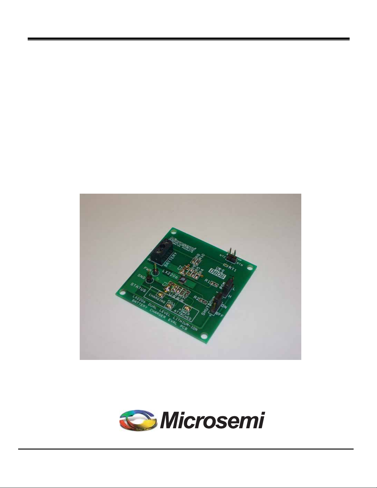
INTRODUCTION TO PRODUCT
The LX2206 Evaluation Board is available from Microsemi for evaluating the performance of the LX2206 Battery Charger
integrated circuit. The component sizes used on the evaluation board facilitate easy probing, however, in practice, smaller
component sizes are recommended to minimize the circuit physical size.
EY FEATURES
K
Two independent programmable charge currents
0.5% Float voltage tolerance
Charging up to 1A.
Charging from USB port.
USB current compliance
Full battery Indicator
CC/CV w thermal Feedback
Battery temp monitor
Precision charge termination
Power Good Indicator
PPLICATIONS
A
MP3 player
PDA
PMC
Digital Camera
Charge cradle
ART SPECIFIC INFORMATION
P
Part Number Product
LX2206ILD
Dual Level Lithium Ion Battery Charger
TABLE 1 – PART INFORMATION
IC EVALUATION BOARDS
LX2206ILD LX2206 EVAL KIT
TABLE 2 – EVALUATION BOARD INFORMATION
Copyright © 2002
Rev. 1.1, 2006-11-17
Microsemi
Integrated Products
11861 Western Avenue, Garden Grove, CA. 92841, 714-898-8121, Fax: 714-893-2570
Page 3
Page 4

LX2206 EVALUATION BOARD USER GUIDE
SCHEMATIC FOR LX2206 EVALUATION BOARD
STATUS
R6
PWR
GND
H
L
I PGM
OFF
ON
SHUTDOWN
C1
10uF
R1
1.00k
R2
1.00k
0.47u
R5
19.6k 110k
2
6
5
8
7
R4
Current
Programming
1
C3
IN
CMP
H/L
SD
HCP
LCP
LX2206
GND
BP
STAT
DCOK
TMP
BAT
3
4
9
10
2.49k
R3
2.49k
R7
2.49k
CHARGING
FULL
POWER
ATTACHED
R9
Not
Used
R8
121k
R10
24.9k
RT1
BAT TEMP
C2
10uF
Battery
Temperature
Lockout
Sensing
NTC
RTN
BAT+
RTN
BATTERY
Figure 1 – LX2206 Evaluation Board Schematic
Copyright © 2002
Rev. 1.1, 2006-11-17
Microsemi
Integrated Products
11861 Western Avenue, Garden Grove, CA. 92841, 714-898-8121, Fax: 714-893-2570
Page 4
Page 5

LX2206 EVALUATION BOARD USER GUIDE
BLOCK DIAGRAM
+
SD
ENABLE
DCOK
TMP
H/L
LCP
UVLO
CHARGE
CONTROL
IN
CHARGE
TERMINATION
CONTROL
COND.
CURRENT
LOW
CHARGING
CURRENT
CONSTANT
VOLTAGE
CONTROL
TEMPERATURE
CONTROL
CONDITIONING
THRESHOLD
STAT
BAT
Copyright © 2002
Rev. 1.1, 2006-11-17
HCP
GND
HIGH
CHARGING
CURRENT
Figure 2 – Simplified Block Diagram
Microsemi
11861 Western Avenue, Garden Grove, CA. 92841, 714-898-8121, Fax: 714-893-2570
Integrated Products
Page 5
Page 6

LX2206 EVALUATION BOARD USER GUIDE
LX2206 EVAL CONNECTIONS
Connections: The LX2206 Evaluation Board has
one power input and one power output connection.
FUNCTION PIN NAME
Input Power PWR 5V +/- 0.65V
Input RTN GND 0V
Battery + BAT+ 0V to 4.3V
Battery - RTN 0V
Jumpers: The LX2206 Evaluation Board has two
position jumper blocks. The jumper can be moved to
select either a high logic level or low logic level. It is
also possible to remove the jumper and apply a
voltage directly to the center pin of the jumper block.
Hookup: The following is a demonstration scenario
that can be used to evaluate the LX2206.
VOLTAGE
and the Negative terminal to the RTN
terminal.
2) Apply a +5V power source to the PWR
terminal and the power supply return to the
GND terminal.
3) Move the SHUTDOWN jumper to the ON
position.
4) The POWER ATTACHED and CHARGING
LEDs should be lit when the battery is
charging and the POWER ATTACHED and
FULL LEDs should be lit when the battery is
fully charged.
5) Monitor the charge current into the battery
with a current probe.
6) Verify that the current changes levels
between approximately 92mA and 460mA
when the I PGM jumper is moved between
its two positions.
7) Verify that moving the SHUTDOWN battery
to the OFF position extinguishes the LEDs
and terminates the charge cycle.
8) The thermal lockout can be tested by
removing RT1 and replacing it with a
variable resistor to simulate the resistance of
RT1 under extreme hot and cold conditions.
1) Apply the single cell Lithium Ion or Lithium
polymer battery to the battery screw terminal
block. Be sure to connect the positive
terminal of the battery to the BAT+ terminal
Copyright © 2002
Rev. 1.1, 2006-11-17
11861 Western Avenue, Garden Grove, CA. 92841, 714-898-8121, Fax: 714-893-2570
Microsemi
Integrated Products
Page 6
Page 7

LX2206 EVALUATION BOARD USER GUIDE
LX2206 TYPICAL TEST HOOKUP
BAT TEMP
NTC
RTN
INTEGRATED PRODUCTS
RT1
R8R9R10
-
3
Single Cell
Lithium Ion
Battery
+
RTN
BAT+
R4
R5
C2
R1
BATTERY
1
LX2206
PWR
+
5V Power
Supply
GND
STATUS
CHARGING
R6
C3
FULL
LX2206 DUAL LEVEL LITHIUM-ION
C1
-
Figure 3 – LX2206 Typical Test Hookup
BATTERY CHARGER EVAL PCB
PCB
LAYOUT RECOMMENDATIONS
It is recommended that C1 and C2 be located within
1cm of the LX2206. The CMP capacitor should be
located close to the IN and CMP pins. Also the high
impedance summing node connecting to the TMP pin
should be kept relatively short to prevent the coupling
of noise into this node. It is important that the LX2206
have a good thermal path to ambient to dissipate
heat. The simplest way to do this is to heatsink the
LX2206 bottom pad directly to the ground plane by
placing 4 or more vias in the ground pad directly
under the LX2206 footprint.
R2
R3
R7
POWER
ATTACHED
3
L
H
I PGM
1
1
13
3
313
ON
OFF
1
1
SHUTDOWN
Copyright © 2002
Rev. 1.1, 2006-11-17
Microsemi
Integrated Products
11861 Western Avenue, Garden Grove, CA. 92841, 714-898-8121, Fax: 714-893-2570
Page 7
Page 8

LX2206 EVALUATION BOARD USER GUIDE
LX2206 PRINTED CIRCUIT BOARD LAYOUT
BAT TEMP
NTC
RTN
INTEGRATED PRODUCTS
RT1
R8R9R10
3
3
RTN
BAT+
1
PWR
GND
STATUS
BATTERY
C2
LX2206
C1
CHARGING
C3
R6
FULL
R5
R4
R1
R2
R3
R7
POWER
ATTACHED
L
H
I PGM
1
1
13
3
313
ON
OFF
1
1
SHUTDOWN
LX2206 DUAL LEVEL LITHIUM-ION
BATTERY CHARGER EVAL PCB
Figure 4 – LX2206 Evaluation Board Layout
Copyright © 2002
Rev. 1.1, 2006-11-17
Microsemi
Integrated Products
11861 Western Avenue, Garden Grove, CA. 92841, 714-898-8121, Fax: 714-893-2570
Page 8
Page 9

LX2206 EVALUATION BOARD USER GUIDE
LX2206 EVALUATION BOARD BILL OF MATERIALS
Line
Item
1 Microsemi IC – Dual Level Li-Ion Charger
2 LED - Amber
3 LED - Red
4 LED - Green
5 Thermistor – NTC, 100k
6 Terminal Block 2 position/ 7mm spacing
7 Header 3 pin 0.100in spacing I PGM, SHUTDN 2
8 Header 2 pin 0.100in spacing BAT TEMP 1
9 Header 1 pin PWR, GND 2
10 Jumper, 2 Pos, 0.100 inch spacing I PGM, SHUTDN 2
11 Printed Circuit Board
Part Description Manufacturer & Part # Case
MISCELLANEOUS COMPONENTS
MICROSEMI LX2206ILD
PANASONIC LNJ414K8YRA
PANASONIC LNJ214K8ARA
PANASONIC LNJ314G8TRA
VISHAY NTHS0402N01N1003J
OST OST/2/7.0
MICROSEMI SGE#3541 X1
Reference
Designators
3x3 MLP U1 1
0603 CHARGING 1
0603 FULL 1
0603 POWER ATTACH 1
0402 RT1 1
BATTERY 1
1
CAPACITORS
Line
Item
1 Capacitor, X5R, 10uF, 10V, 10%
2 Capacitor, X7R, 0.47uF, 16V, 20%
Part Description Part Number Case
TAIYO YUDEN LMK316BJ106KD-T
TAIYO YUDEN EMK212BJ474KD-T
1206 C1,2 2
0805 C3 1
Reference
Designators
RESISTORS
Line
Item
1 Resistor, 1.00K, 1%, 1/10W
2 Resistor, 2.49K, 1%, 1/10W
3 Resistor, 110K, 1%, 1/10W
4 Resistor, 19.6K, 1%, 1/10W
5 Resistor, 121K, 1%, 1/10W
6 Resistor, 24.9K, 1%, 1/10W
Part Description Part Number Case
PANASONIC ERJ-6ENF1001V
PANASONIC ERJ-6ENF2491V
PANASONIC ERJ-6ENF1103V
PANASONIC ERJ-6ENF1962V
PANASONIC ERJ-6ENF1213V
PANASONIC ERJ-6ENF2492V
0805 R1,2 2
0805 R3,6,7 3
0805 R4 1
0805 R5 1
0805 R8 1
0805 R10 1
Reference
Designators
Qty
Qty
Qty
Copyright © 2002
Rev. 1.1, 2006-11-17
Microsemi
Integrated Products
11861 Western Avenue, Garden Grove, CA. 92841, 714-898-8121, Fax: 714-893-2570
Page 9
 Loading...