

Page 1

James Hamilton Electrical Pty Ltd (Inc in Qld) A.C.N. 010 848 389 trading as
Power Drive Systems
Generator Control Specialists
48A Ainsdale Street Telephone: 0500 800 225 P.O. Box 30
West Chermside, Qld 4032 Facsimile: 3350 1654 Grange, Qld 4051
Australia Mobile: 0427 22 00 18 Australia
email: info@powersystems.com.au www.powersystems.com.au
DUNLITE UVR100
AUTOMATIC VOLTAGE REGULATOR
Page 2

POWER DRIVE SYSTEMS
DUNLITE UVR100 AUTOMATIC VOLTAGE REGULATOR
1
GENERAL
This regulator is a solid-state device primarily designed to give precise and stable voltage regulation of an
alternator under adverse operating conditions.
The regulator is suitable for operation on either single or three phase 240/415 or 120/208 volt brushless
alternators.
OPERATION
The regulator senses the output voltage of the alternator and compares this value with a pre-set voltage
reference within its circuitry. The regulator constantly adjusts the field excitation of the alternator to
compensate for variations in load and prime mover speed, and holds the output voltage to within plus or
minus 1.5% no load to full load, unity to 0.8 power factor lagging, and a speed variation of 4.5%.
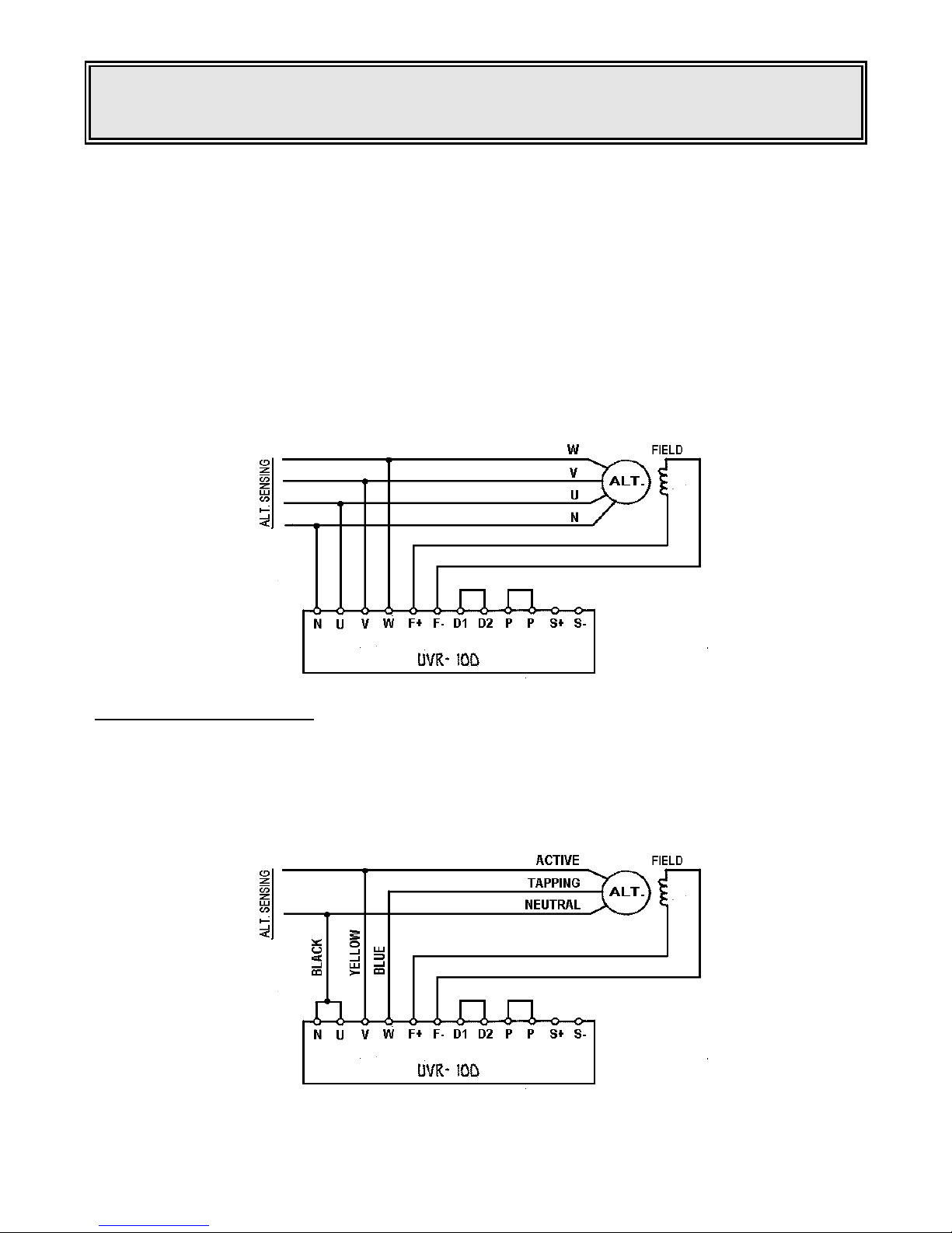
CONNECTION DETAILS
There are 14 screw terminals on the regulator and their functions are as follows. Early models are labelled
R.W.B in place of U.V.W.
N - Must always be connected to the neutral of the alternator.
U & V - Sensing terminals for voltage regulation.
W - Power terminal for exciter field.
F+ F- - Alternator exciter field terminals.
pp - Terminals for a 5k remote voltage adjustment potentiometer.
D1,D2 - Terminals for the addition of drooping circuit for parallel operation.
S+ S1 - Terminals for remote indication of the SCOOP operation, Series 2000 control (later models only).
THREE PHASE OPERATION
The regulator must be adjusted for either 415 or 208 volts sensing, depending on the available sensing
leads on the alternator. If in doubt, contact Dunlite, stating alternator serial number.
Open the regulator box by unclipping the side catches, and adjacent to the transformer, will be found four
pins connected to various taps of the transformer. The purple fly lead must be connected to the relevant
pin to match the regulator to the available sensing outputs of the alternator.
Starting from the pin nearest the transformer, the sensing voltages are 120V, 208V, 240V, 415V.
_____________________________________________________________________________________
Page 3
POWER DRIVE SYSTEMS
DUNLITE UVR100 AUTOMATIC VOLTAGE REGULATOR
2
NOTE
When the regulator is fitted within a separate control cubicle, the terminals U, V, W and N will have been
factory connected to AC supply points within the cubicle.
Similarly, the voltage adjustment terminals PP may have been connected to a separate potentiometer normally these terminals will be bridged, as will also the droop circuit terminals D1, D2.
The only terminals requiring connection when installing the plant will be the F+ and F- (grey and white
respectively) and a small terminal block is fitted within the alternator terminal box for interconnection
purposes.
Once the above has been completed, the regulator may be connected to the alternator. N to neutral, U to
Red phase, V to White phase, W to Blue phase, F+ and F- to Field. D1 D2 and PP must be bridged if not
connected to external potentiometers ~ see diagram.
Note: Later model UVR100 regulator violet wires to S+ & S (See SCOOP Section)
SINGLE PHASE OPERATION
As for three phase operation, the regulator must be adjusted for either 240 or 120 volt sensing. This can be
done by the purple fly lead as for three phase operation.
For single phase operation, terminals N and U are bridged and connected to neutral, terminals V and W
are bridged and connected to the alternator sensing. The remaining terminals are connected as for three
phase operation. See diagram.
_____________________________________________________________________________________
Page 4

POWER DRIVE SYSTEMS
DUNLITE UVR100 AUTOMATIC VOLTAGE REGULATOR
3
CONTROLS
There are three standard controls on each regulator. They are -
1. Voltage Adjust
This potentiometer varies the internal voltage reference of the regulator, hence varying the alternator
output voltage over a range of plus or minus 10%. An external 5K potentiometer may be added to terminals
PP for remote voltage adjustment. Under these circumstances RVI, should be fully clockwise.
2. Stability
This potentiometer varies the stability the system and should initially be set in an anti-clockwise position
and rotated clockwise to give optimum stability and response characteristics. Once set it should not be
necessary to carry out further adjustment to this control.
3. SCOOP
All UVR100 regulators incorporate SCOOP (Speed, Current Operated, Overload Protection) as a standard
feature.
If the engine slows down due to either an overload on the alternator or a mechanical fault in the engine, the
exciter field voltage will increase. The same applies if the engine speed remains constant whilst the
alternator is overloaded due to excessive current being drawn, or a very low power factor load.
The SCOOP feature of the regulator is built in to protect the alternator against such overloads. It senses
the average voltage being applied to the alternator exciter winding, and if this applied voltage exceeds a
pre-set safe maximum value, the SCOOP inhibits the triggering of the thyristor which controls the current
supply to the exciter winding. The result is the alternator output voltage falls to approximately 50 volts.
Allowance is made for temporary overloads, such as those encountered when starting electric motors, by
the addition of a built-in delay. This factory pre-set, non-adjustable, feature delays the operation of the
SCOOP function for approximately 20 seconds.
If the alternator output voltage is lost due to the operation of SCOOP the voltage will remain at its SCOOP
level until the generating set is shut down. Stopping the set will automatically reset the function. If the
reason for the operation of SCOOP is not immediately obvious, it is advisable that an investigation is
carried out before any attempt to restart is made. If the cause of the failure has not been determined and
rectified, the set will again lose output voltage approximately 30 seconds after restart.
The operation of SCOOP and/or certain short circuit conditions may result in the loss of residual
magnetism in the alternator exciter field. In such cases, refer to the section entitled "Repolarisation".
Under no circumstances must any voltage from an outside source be applied to the voltage
regulator field terminals. Failure to observe this point may result in permanent damage to the regulator.
_____________________________________________________________________________________
Page 5

POWER DRIVE SYSTEMS
DUNLITE UVR100 AUTOMATIC VOLTAGE REGULATOR
4
CONTROLS (cont' d)
3. SCOOP
(cont'd)
SCOOP Adjustment
As previously stated, the point at which this function operates is pre-set at the factory so as to limit. to a
safe maximum value, the voltage applied to the exciter field. This voltage varies according to the particular
size and type of alternator and should not normally require adjustment. If, however, under operational
conditions it is found that the SCOOP function is frequently re-~- ting in loss of alternator output, without
any apparent cause,,,-it may be necessary to adjust the voltage at which SCOOP operates. In such cases,
it will be necessary to contact the factory to determine the normal cut-out voltage and then carry out the
tests detailed below.
(Note: To avoid any delay in obtaining this information, please specify both the type and serial numbers of
the generating set when making enquiry.)
1. Connect a high impedance 0-50 volts DC voltmeter across the field supply terminals
positive and negative.
2. Run the generating set and apply the full rated load and note the voltage being
applied to the exciter field.
3. On engines incorporating a hand throttle, adjust the speed of the prime mover until
the field voltage equals the SCOOP cut-out voltage recommended by the factory.
4. Adjust the SCOOP control until the red SCOOP indicator LED starts to illuminate.
5. Return the hand throttle setting to normal after the final adjustment has been made.
On engines which do not incorporate a hand throttle, the load should be increased
to achieve the field volts as specified by the factory.
DO NOT run the set on overload for extended periods when carrying out these tests, or the alternator may
sustain permanent damage, and UNDER NO CIRCUMSTANCES ALLOW THE SET TO RUN WITH THE
FIELD VOLTS IN EXCESS OF THE MAXIMUM VALUE SPECIFIED BY THE FACTORY.
It is possible to adjust the SCOOP to operate at a lower voltage, thereby reducing the tolerable degree of
overload; however, when doing so account must be taken of the increase in field volts required to cover
low power factor loads and high ambient temperatures.
The SCOOP indicator will illuminate as soon as an overload or low speed condition arises and will remain
illuminated after the SCOOP has de-energised the alternator.
_____________________________________________________________________________________
Page 6

POWER DRIVE SYSTEMS
DUNLITE UVR100 AUTOMATIC VOLTAGE REGULATOR
5
SCOOP REMOTE INDICATION S+ S- (Later models)
S+ and S- terminal s are used for remote indication of the SCOOP operation. The output is an optically
coupled silicon NPN phototransistor. The ouput is connected via the alternator terminal box to a Series
2000 control which has the necessary interface.
If SCOOP trips as per normal overload protection etc. the opto coupled transistor will switch and shut the
engine down. (See operating manual Series 2000 MK III).
Connection details SCOOP S+ S-
To No. 7 engine terminal
Series 2000 control cubicle
Figure 1
Connect as for Figure 1 when neutral and battery negative are common to earth.
To No. 7 engine terminal
To No. 1 engine terminal
Battery negative
Series 2000 control cubicle
Figure 2
Connect as for Figure 2 when separate neutral and battery negative is required.
Battery negative is earthed.
_____________________________________________________________________________________
Page 7

POWER DRIVE SYSTEMS
DUNLITE UVR100 AUTOMATIC VOLTAGE REGULATOR
6
REMOTE VOLTAGE CONTROL
Terminals PP
The UVR100 regulator has remote voltage facilities where the voltage range can be varied up to 10%.
Remove bridge from PP and fit an external 5K 2W potentiometer. Turn RV1 voltage adjusting
potentiometer on the regulator fully clockwise so as to have full voltage range adjustment on the external
potentiometer.
It is advisable to use screen cable for the remote potentiometer connection as this will prevent noise from
being transmitted to the AVR and causing voltage stability problems.
See Figure 3.
Figure 3
_____________________________________________________________________________________
Page 8

POWER DRIVE SYSTEMS
DUNLITE UVR100 AUTOMATIC VOLTAGE REGULATOR
7
DROOP FACILITY
Terminals D1 D2
The UVR100 regulator has quadrature droop facilities for parallel operation.
The addition of a drooping kit will make the UVR100 suitable for parallel operation.
Quadrature droop allows load sharing of reactive load (kVAR) only, since kW load sharing is a function of
the prime mover.
Part of the droop kit will be a class 2.0 (Australian Standard C388) ring current transformer, with 5A 10
(ten) VA secondary rating and ratio to suit twice the alternator output. This current transformer must be
placed in the Blue phase. It is to be noted that the UVR100 senses Red and White phase voltage and to
achieve quadrature droop, current must be sensed in the Blue phase. See diagram.
Nominal value of fixed resistor 'Rl' is 1 ohm 20W and of adjustable potentiometer 'R2’ 30 ohm 2W. These
values are subject to change, dependant on the number of alternators to be paralleled, and advice should
be obtained from the factory in this regard.
R2 must be adjusted on both plants for kVAR load sharing.
See 'Parallel Operation’ Appendix C.
_____________________________________________________________________________________
Page 9

POWER DRIVE SYSTEMS
DUNLITE UVR100 AUTOMATIC VOLTAGE REGULATOR
8
OPERATING UNDER EXTREME ADVERSE CONDITIONS
For operation under extreme adverse conditions ( le. lightning strikes etc.) the regulator may be used
without additions, provided the power terminal (B) is connected to a centre tap of the alternator (ie. on 240
volt machine, connect terminal B to a 120 volt tap).
Where a centre tap is not available, an isolation step down transformer may be used to supply power to
terminal B – see diagran. Contact the factory for VA rating of transformer, stating alternator serial number.
Where severe transients may be induced by direct lightning strikes, lightning supperssors should be used
on alternator outputs.
_____________________________________________________________________________________
Page 10

POWER DRIVE SYSTEMS
DUNLITE UVR100 AUTOMATIC VOLTAGE REGULATOR
9
FAULT LOCATION
If the generating set runs at the correct speed, but will not generate, check as follows -
1. Shut down the set.
2. Check all wiring between the alternator, distribution board and load.
3. Check the external potentiometer terminals PP are bridged. If an external
potentiometer is being used, check it and its connecting leads for continuity.
Check droop terminals DI, D2 are bridged if not in use.
4. Isolate the main stator windings and exciter field windings and check
for continuity and the insulation resistance to earth and between the windings.
(Contact Dunlite for specific ohmic values, stating alternator serial number.)
Note Before testing insulation resistance with any high voltage test equipment, make certain
the main alternator voltage regulator and the battery charging voltage regulator leads are
disconnected and insulated to prevent damage to solid state components.
5. Disconnect the exciter field leads from the regulator F+ and F-, carefully noting the
respective lead/terminal positions (grey lead to F+, white lead to F-).
Connect the white lead to the negative of the starter battery. Place a 0-5 amp DC ammeter in
series with the grey lead, and connect to the lowest battery tap.
Start up the alternator and note alternator output voltage. Increase the tapping voltage until the
alternator voltage is approximately 240 voltage.
Note Do not connect any voltage from any source to these leads whilst they are
connected to the regulator, or permanent damage to the regulator may occur.
Check the current with the 0-5 ammeter, and if this is in excess of the factory
recommended limit of the alternator, the fault probably lies within the alternator.
The fault could have caused the regulator to fail, hence regulator fault finding procedure must be
carried out.
REPOLARISATION
It is posible, after prolonged periods of storage, or as a result of certain fault conditions, that the alternator
will not have sufficient residual magnetic field for initial excitation. In such circumstances, the following
procedure will re-establish the residual field -
1. Shut down the set.
2. Disconnect the exciter field leads from the regulator (Field Supply positive and negative) carefully
noting the respective lead/terminal positions.
3. Momentarily, connect the leads from the exciter field across the starter battery with the lead from
the positive terminal being taken to the positive battery terminal and the lead from the negative
terminal to the negative battery terminal .
(The starter battery may be either 12 or 24 volt.)
Take care not to connect the starter battery to these leads whilst they are connected to the
regulator, or, permanent damage to the regulator may occur.
4. Reconnect the exciter field leads to the regulator.
If the alternator still fails to excite, the fault may be in the regulator.
_____________________________________________________________________________________
Page 11

POWER DRIVE SYSTEMS
DUNLITE UVR100 AUTOMATIC VOLTAGE REGULATOR
10
UVR100 REGULATOR FAULT FINDING CHART
Instrument: Multimeter 20K Sensitivity. Ref:
Drg. No. 0212-J-03
Fault
Diagnose
High Voltage
300V AC
(Danger – run for periods of 1-2 mins. only to avoid
excess field current and disconnect all load)
1. Check correct transformer tap to suit alternator sensing for three
phase or single phase operation.
2.
Check all leads to regulator are secure.
3. Check D1, D2 terminals are bridged or connected to correct
burden resistor-as for parallel operation.
4.
Check printed circuit board for fractured track or loose component.
5. Check transformer secondary voltage at Bl 32 volts AC plus or
minus 2 volts.
6. Check DC output voltage across Cl
39 volts DC plus or minus 1 volt.
7.
Check transistor TR2 for open circuit.
8.
Check D5 for short circuit.
Fault
Diagnose
Low Voltage
50V AC
1.
Check correct transformer tap to suit alternator sensing for three
phase or single phase operation.
2.
Check all leads to regulator are secure.
3. Check PP terminals are bridged or connected to correct 5K
external potentiometer.
4.
Check printed circuit board for fractured track or loose component.
5.
Check for short circuit flywheel diode 04 across F+ F-.
6.
Check for short circuit or open circuit main thyristor D5.
7. Check residual voltage and repolarise if necessary as per
"repolarisation" procedure.
(Note: Residual ranges from 10-50V AC approx.)
8.
Check transistor TR2 for short circuit.
9.
Check SCOOP operation.
Fault
Diagnose
Continually losing
voltage output.
1. Check all leads are secure.
2. Check SCOOP setting as per SCOOP adjustment procedure.
3. Ensure that alternator is not overloaded.
4. Check that engine speed is constant.
Fault
Diagnose
Unstable voltage.
1.
Check all leads are secure.
2. Check stability potentiometer as per stability adjustment
procedure.
3.
Check transistor TR1 for open or short circuit.
4.
Check diode D1 for open or short circuit.
5.
Check printed circuit board for fractured track or loose component.
Note:
If unable to find fault, return to Dunlite for repairs, with brief history of type of failure.
_____________________________________________________________________________________
Page 12

POWER DRIVE SYSTEMS
DUNLITE UVR100 AUTOMATIC VOLTAGE REGULATOR
11
Mains Check of the UVR100
Connect the UVR100 for 240 volt single phase operation.
Connect a 40 watt globe between F+ F-.
Bridge out terminals D1,D2 and PP separately.
Set voltage control potentiometer RV1 fully anti-clockwise.
Connect the N and U terminals to the neutral of the mains.
Connect the V and W terminals to the active of the mains via a 1 amp fuse.
Switch on the mains.
The 40 watt globe should not illuminate.
Turn the potentiometer RV1 fully clockwise and the globe should illuminate.
At the same time the red SCOOP indicator LED will also illuminate.
After a period of 15-20 seconds, the 40 watt globe will turn off.
Switch mains off immediately after globe turns off otherwise damage will occur to SCOOP circuit.
Under these conditions the UVR100 is functioning correctly.
_____________________________________________________________________________________
 Loading...