

Power Drive PD210D, PD610D, PD612D, 7920KD, PD612KLD Assembly And Installation Manual
...
GARAGE DOOR OPENER
ASSEMBLY/INSTALLATION MANUAL
■
Please read this manual and the enclosed safety materials carefully!
■
Fasten the manual near the garage door after installation.
■
The door WILL NOT CLOSE unless the Protector System®is connected
and properly aligned.
■
Periodic checks of the opener are required to ensure safe operation.
■
The model number label is located under the light lens on the front panel of
your opener.
When you see these Safety Symbols and Signal Words
on the following pages, they will alert you to the
possibility of serious injury or death if you do not
comply with the warnings that accompany them. The
hazard may come from something mechanical or from
electric shock. Read the warnings carefully.
When you see this Signal Word on the following pages,
it will alert you to the possibility of damage to your
garage door and/or the garage door opener if you do
not comply with the cautionary statements that
accompany it. Read them carefully.
Mechanical
Electrical
WARNING
WARNING
WARNING
WARNING
This garage door opener has been designed and tested to offer safe service provided it is installed, operated,
maintained and tested in strict accordance with the instructions and warnings contained in this manual.
IMPORTANT SAFETY NOTES
PD210D • PD212D
248730
PD610D • PD612D • 7920KD
PD612KLD • 48930D
The Chamberlain Group, Inc.
845 Larch Avenue
Elmhurst, Illinois 60126-1196
www.chamberlain.com
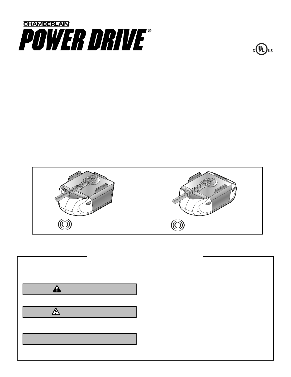
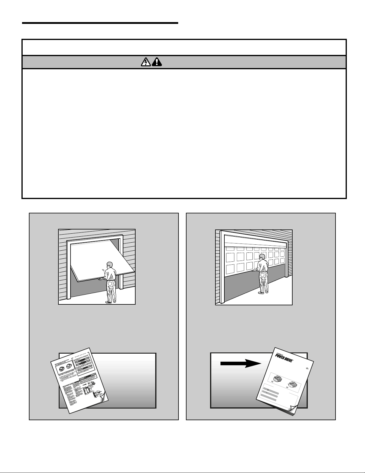
There are two types of garage door openers pictured. Yours may appear slightly different.
WARNING
WARNING
CAUTION
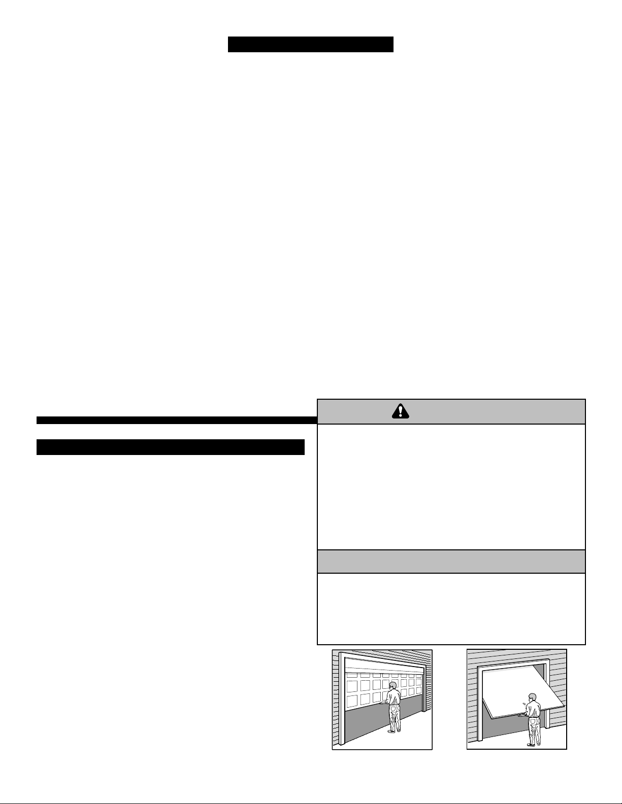
Before you begin:
• Disable locks (contact your door manufacturer for
information on disabling your door locks.)
• Remove any ropes connected to garage door.
• Complete the following test to make sure your garage
door is balanced and is not sticking or binding:
1. Lift the door about halfway as shown. Release the
door. If balanced, it should stay in place, supported
entirely by its springs.
2. Raise and lower the door to see if there is any
binding or sticking.
If your door binds, sticks, or is out of balance, call a
trained door systems technician.
If you have a one-piece door, the installation of your
garage door opener will be different. Follow the assembly
instructions included in this manual then proceed to the
Installation Instructions For One-Piece Doors included with
the garage door opener.
To prevent damage to garage door and opener:
• ALWAYS disable locks BEFORE installing and operating
the opener.
• ONLY operate garage door opener at 120V, 60 Hz to avoid
malfunction and damage.
To prevent possible SERIOUS INJURY or DEATH:
• ALWAYS call a trained door systems technician if garage door
binds, sticks, or is out of balance. An unbalanced garage
door may not reverse when required.
• NEVER try to loosen, move or adjust garage door, door
springs, cables, pulleys, brackets or their hardware, ALL of
which are under EXTREME tension.
• Disable ALL locks and remove ALL ropes connected to
garage door BEFORE installing and operating garage door
opener to avoid entanglement.
WARNING
WARNING
WARNING
WARNING
Sectional Door
Preparing Your Garage Door . . . . . . . . . . . . . . . . . . . . . 2
Completed Installation . . . . . . . . . . . . . . . . . . . . . . . . . . 3
Tools Needed. . . . . . . . . . . . . . . . . . . . . . . . . . . . . . . . . . 4
Opener Contents. . . . . . . . . . . . . . . . . . . . . . . . . . . . . . . 4
Assembly Hardware . . . . . . . . . . . . . . . . . . . . . . . . . . . . 5
Installation Hardware . . . . . . . . . . . . . . . . . . . . . . . . . . . 5
Assembly . . . . . . . . . . . . . . . . . . . . . . . . . . . . . . . . . . . 6-8
Installation
Installation safety instructions . . . . . . . . . . . . . . . . . . . . . . 9
Install the header bracket . . . . . . . . . . . . . . . . . . . . . . . . 10
Mount the header bracket . . . . . . . . . . . . . . . . . . . . . . . . 11
Position and hang motor unit . . . . . . . . . . . . . . . . . . . . . 12
Fasten the door bracket . . . . . . . . . . . . . . . . . . . . . . . . . 13
Attach door to trolley. . . . . . . . . . . . . . . . . . . . . . . . . . . . 14
Installing the door control . . . . . . . . . . . . . . . . . . . . . . . . 15
Installing the light bulb(s) . . . . . . . . . . . . . . . . . . . . . . . . 16
Electrical requirements . . . . . . . . . . . . . . . . . . . . . . . . . . 16
Install the Protector System
®
. . . . . . . . . . . . . . . . . . . 17-18
Wire safety sensor . . . . . . . . . . . . . . . . . . . . . . . . . . . . . 19
Adjustment
Adjust the UP and DOWN travel limits . . . . . . . . . . . . . . 20
Adjust the forces . . . . . . . . . . . . . . . . . . . . . . . . . . . . . . . 21
Test the safety reversal system . . . . . . . . . . . . . . . . . . . 22
Test the Protector System
®
. . . . . . . . . . . . . . . . . . . . . . . 22
Operation
Important Safety Information . . . . . . . . . . . . . . . . . . . . . 23
Using your garage door opener . . . . . . . . . . . . . . . . . . . 23
Using the wall-mounted door control . . . . . . . . . . . . . . . 24
Care of your opener . . . . . . . . . . . . . . . . . . . . . . . . . . . . 24
To open the door manually . . . . . . . . . . . . . . . . . . . . . . . 24
Having a Problem? . . . . . . . . . . . . . . . . . . . . . . . . . . . . 25
Diagnostic Chart . . . . . . . . . . . . . . . . . . . . . . . . . . . . . . 26
Programming
To add or reprogram an additional
hand-held remote control . . . . . . . . . . . . . . . . . . . . . . . . 27
To control the opener lights . . . . . . . . . . . . . . . . . . . . . . 27
Multi-function remotes. . . . . . . . . . . . . . . . . . . . . . . . . . . 27
To add, reprogram or
change a keyless entry PIN . . . . . . . . . . . . . . . . . . . . . . 28
To change an existing, known PIN . . . . . . . . . . . . . . . . . 28
To set a temporary PIN. . . . . . . . . . . . . . . . . . . . . . . . . . 29
To erase all codes from motor unit memory . . . . . . . . . . 29
The remote control battery . . . . . . . . . . . . . . . . . . . . . . . 29
Repair Parts
Rail assembly parts . . . . . . . . . . . . . . . . . . . . . . . . . . . . 30
Installation parts . . . . . . . . . . . . . . . . . . . . . . . . . . . . . . . 30
Motor unit assembly parts. . . . . . . . . . . . . . . . . . . . . . . . 31
Accessories. . . . . . . . . . . . . . . . . . . . . . . . . . . . . . . . . . 32
Notes. . . . . . . . . . . . . . . . . . . . . . . . . . . . . . . . . . . . . 33-34
Warranties . . . . . . . . . . . . . . . . . . . . . . . . . . . . . . . . . . . 35
Repair Parts and Service . . . . . . . . . . . . . . . . . . . . . . . 36
TABLE OF CONTENTS
PREPARING YOUR GARAGE DOOR
2
One-Piece Door
See addendum
WARNING
CAUTION
3
PLANNING
Identify the type and height of your garage door. If you
have a one-piece door, follow the assembly
instructions contained in this manual and refer to the
Installation Instructions One-Piece Door for
installation procedures. Survey your garage area to see
if any of the conditions below apply to your installation.
Additional materials may be required. You may find it
helpful to refer back to this page and the accompanying
illustrations as you proceed with the installation of your
opener.
Depending on your requirements, there are several
installation steps which may call for materials or hardware
not included in the carton.
• Installation Page 10 – Look at the wall or ceiling above
the garage door. The header bracket must be securely
fastened to structural supports.
• Installation Page 12 – Do you have a finished ceiling in
your garage? If so, a support bracket and additional
fastening hardware may be required.
• Installation Page 13 – Do you have a steel, aluminum,
fiberglass or glass panel door? If so, horizontal and
vertical reinforcement is required.
• Installation Page 18 – Depending upon garage
construction, extension brackets or wood blocks may be
needed to install sensors.
• Installation Page 18 – Alternate floor mounting of the
safety reversing sensor will require hardware not
provided.
• Do you have an access door in addition to the garage
door? If not, Model 7702CB Outside Quick Release is
required. See Accessories page.
• Look at the garage door where it meets the floor. Any
gap between the floor and the bottom of the door must
not exceed 1/4" (6 mm). Otherwise, the safety reversal
system may not work properly. See Adjustment Step 3.
Floor or door should be repaired.
• The opener should be installed above the center of the
door. If there is a torsion spring or center bearing plate
in the way of the header bracket, it may be installed
within 4 feet (1.22 m) to the left or right of the door
center.
• If your door is more than 7 feet (2.13 m) high, see rail
extension kits listed on Accessories page 32.
Without a properly working safety reversal system, persons
(particularly small children) could be SERIOUSLY INJURED or
KILLED by a closing garage door.
• The gap between the bottom of the garage door and the floor
MUST NOT exceed 1/4" (6 mm). Otherwise, the safety
reversal system may not work properly.
• The floor or the garage door MUST be repaired to eliminate
the gap.
WARNING
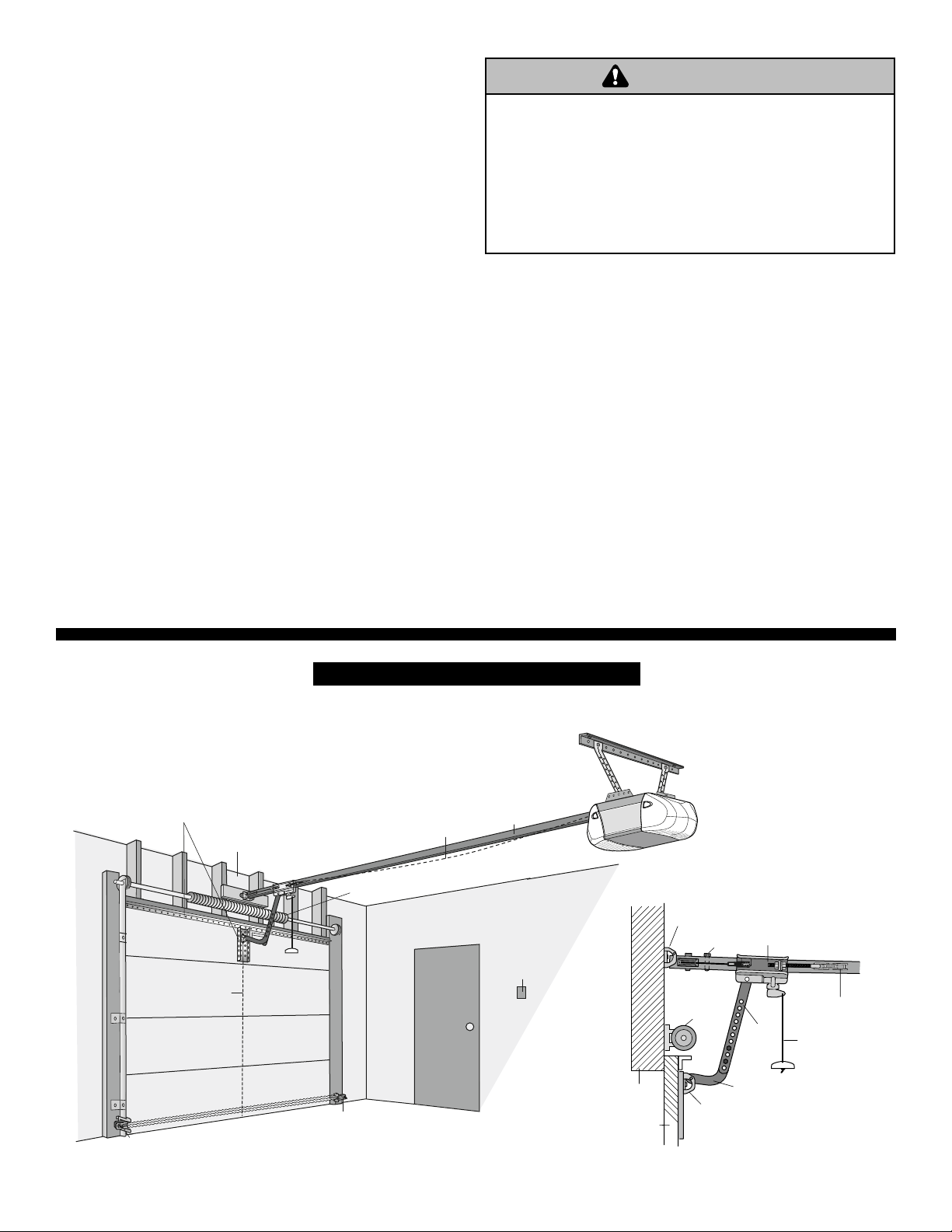
COMPLETED INSTALLATION
Trolley
Header
Wall
Garage
Door
Header
Bracket
Straight
Door
Arm
Emergency
Release
Rope & Handle
Door
Bracket
Curved
Door
Arm
Garage
Door
Spring
Chain
Trolley
Stop Bolt
CLOSED POSITION
WARNING
Horizontal and vertical reinforcement
is needed for lightweight garage doors
(fiberglass, steel, aluminum, door with
glass panels, etc.) See page 13 for details.
Header Wall
Safety Reversing
Sensor
Center of
Garage door
Gap between floor
and bottom of door
must not exceed 1/4"
FINISHED CEILING
Support bracket &
fastening hardware
is required.
See page 12.
Slack in chain tension
is normal when
garage door is closed.
Torsion Spring
Safety
Reversing
Sensor
Access
Door
Rail
Wall-mounted
Door Control
Chain and Cable in
Dispensing Carton
Straight Door
Arm Section
Hanging Brackets
Chain Spreader
with Screws
Motor Unit with Light Lenses
(varies depending
upon model purchased)
Rail
Center/Back
Sections (4)
Rail
Front (header)
Section (1)
“U” Bracket
A11
Idler Pulley
(included with hardware)
A12
Trolley
A13
Header Bracket
A14
Door Bracket
A15
A9
Door
Control
All Other
Models
L
O
C
K
LI
G
H
T
Remote Control Transmitter
A16
Curved Door
Arm Section
A1
A5
A2
A3
A4
A7
A8
(2) Safety Reversing Sensors
(1 Sending Eye and 1 Receiving Eye)
with 2-Conductor White and White/Black
Bell Wire attached
A17
Safety Sensor
Bracket (2)
A10
A18 Assembly and
Installation Hardware
Safety Labels
and Literature
Keyless Entry
Models
PD210D (1)
PD212D (2)
248730 (1)
Models
PD610D (1)
PD612D (2)
PD612KLD (2)
48930D (2)
A19
G
A
R
A
G
E
D
O
O
R
O
P
E
N
E
R
A
S
S
E
M
B
L
Y
/
I
N
S
T
A
L
L
A
T
I
O
N
M
A
N
U
A
L
■
P
le
a
s
e
r
e
a
d
t
h
i
s
m
a
n
u
a
l
a
n
d
t
h
e
e
n
c
l
o
s
e
d
s
a
f
e
t
y
m
a
t
e
r
ia
l
s
c
a
r
e
f
u
l
l
y
!
■
F
a
s
t
e
n
t
h
e
m
a
n
u
a
l
n
e
a
r
t
h
e
g
a
r
a
g
e
d
o
o
r
a
f
t
e
r
i
n
s
t
a
ll
a
t
i
o
n
.
■
T
h
e
d
o
o
r
W
I
L
L
N
O
T
C
L
O
S
E
u
n
l
e
s
s
t
h
e
P
r
o
t
e
c
t
o
r
S
y
s
t
e
m
®
i
s
c
o
n
n
e
c
t
e
d
a
n
d
p
r
o
p
e
r
l
y
a
li
g
n
e
d
.
■
P
e
r
i
o
d
i
c
c
h
e
c
k
s
o
f
t
h
e
o
p
e
n
e
r
a
r
e
r
e
q
u
ir
e
d
t
o
e
n
s
u
r
e
s
a
f
e
o
p
e
r
a
t
i
o
n
.
■
T
h
e
m
o
d
e
l
n
u
m
b
e
r
l
a
b
e
l
i
s
l
o
c
a
t
e
d
u
n
d
e
r
t
h
e
l
i
g
h
t
l
e
n
s
o
n
t
h
e
f
r
o
n
t
p
a
n
e
l
o
f
y
o
u
r
o
p
e
n
e
r
.
W
h
e
n
y
o
u
s
e
e
t
h
e
s
e
S
a
f
e
t
y
S
y
m
b
o
l
s
a
n
d
S
i
g
n
a
l
W
o
r
d
s
o
n
t
h
e
f
o
l
l
o
w
i
n
g
p
a
g
e
s
,
t
h
e
y
w
i
l
l
a
l
e
r
t
y
o
u
t
o
t
h
e
p
o
s
s
i
b
i
l
i
t
y
o
f
s
e
r
i
o
u
s
i
n
j
u
r
y
o
r
d
e
a
t
h
i
f
y
o
u
d
o
n
o
t
c
o
m
p
l
y
w
i
t
h
t
h
e
w
a
r
n
i
n
g
s
t
h
a
t
a
c
c
o
m
p
a
n
y
t
h
e
m
.
T
h
e
h
a
z
a
r
d
m
a
y
c
o
m
e
f
r
o
m
s
o
m
e
t
h
i
n
g
m
e
c
h
a
n
i
c
a
l
o
r
f
r
o
m
e
l
e
c
t
r
i
c
s
h
o
c
k
.
R
e
a
d
t
h
e
w
a
r
n
i
n
g
s
c
a
r
e
f
u
l
l
y
.
W
h
e
n
y
o
u
s
e
e
t
h
i
s
S
i
g
n
a
l
W
o
r
d
o
n
t
h
e
f
o
l
l
o
w
i
n
g
p
a
g
e
s
,
i
t
w
i
l
l
a
l
e
r
t
y
o
u
t
o
t
h
e
p
o
s
s
i
b
i
l
i
t
y
o
f
d
a
m
a
g
e
t
o
y
o
u
r
g
a
r
a
g
e
d
o
o
r
a
n
d
/
o
r
t
h
e
g
a
r
a
g
e
d
o
o
r
o
p
e
n
e
r
i
f
y
o
u
d
o
n
o
t
c
o
m
p
l
y
w
i
t
h
t
h
e
c
a
u
t
i
o
n
a
r
y
s
t
a
t
e
m
e
n
t
s
t
h
a
t
a
c
c
o
m
p
a
n
y
i
t
.
R
e
a
d
t
h
e
m
c
a
r
e
f
u
l
l
y
.
M
e
c
h
a
n
ic
a
l
E
l
e
c
t
r
i
c
al
W
W
A
R
N
ARN
IN
G
ING
WARN
ING
WARN
ING
W
W
A
R
N
ARN
IN
G
ING
WARN
ING
C
A
U
T
IO
N
CAUTION
WARN
ING
WARN
ING
T
h
i
s
g
a
r
a
g
e
d
o
o
r
o
p
e
n
e
r
h
a
s
b
e
e
n
d
e
s
i
g
n
e
d
a
n
d
t
e
s
t
e
d
t
o
o
f
f
e
r
s
a
f
e
s
e
r
v
i
c
e
p
r
o
v
i
d
e
d
i
t
i
s
i
n
s
t
a
l
l
e
d
,
o
p
e
r
a
t
e
d
,
m
a
i
n
t
a
i
n
e
d
a
n
d
t
e
s
t
e
d
i
n
s
t
r
i
c
t
a
c
c
o
r
d
a
n
c
e
w
i
t
h
t
h
e
i
n
s
t
r
u
c
t
i
o
n
s
a
n
d
w
a
r
n
i
n
g
s
c
o
n
t
a
i
n
e
d
i
n
t
h
i
s
m
a
n
u
a
l
.
I
M
P
O
R
TA
N
T
S
A
F
E
T
Y
N
O
T
E
S
P
D
2
1
0
D
•
P
D
2
1
2
D
P
D
6
1
0
D
•
P
D
6
1
2
D
•
7
5
2
0
D
•
P
D
6
1
2
K
L
D
•
4
8
9
3
0
D
T
h
e
C
h
a
m
b
e
r
l
a
i
n
G
r
o
u
p
,
I
n
c
.
8
4
5
L
a
r
c
h
A
v
e
n
u
e
E
l
m
h
u
r
s
t
,
I
l
l
i
n
o
i
s
6
0
1
2
6
-
1
1
9
6
w
w
w
.
c
h
a
m
b
e
r
l
a
i
n
.
c
o
m
T
h
e
r
e
a
r
e
t
w
o
t
y
p
e
s
o
f
g
a
r
a
g
e
d
o
o
r
o
p
e
n
e
r
s
p
i
c
t
u
r
e
d
.
Y
o
u
r
s
m
a
y
a
p
p
e
a
r
s
l
i
g
h
t
l
y
d
i
ff
e
r
e
n
t
.
A6
7920KD (2)
Models
PD612KLD (1)
7920KD (1)
A20
C
L
O
S
E
D
O
P
E
N
Garage Door Monitor
(Model 7920KD only)
Door Control Button
Model 248730 ONLY
A21
4
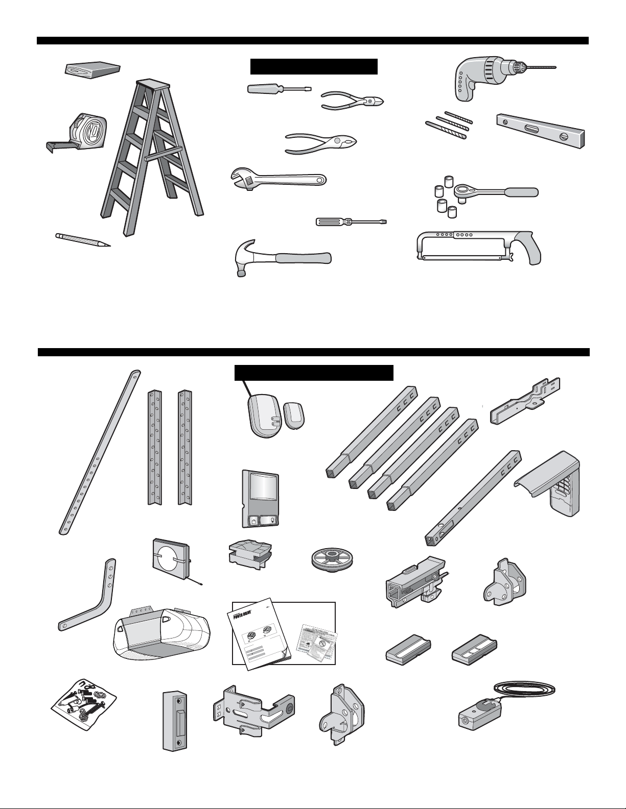
Your garage door opener is packaged in one carton which contains the motor unit and the parts illustrated below. Note
that accessories will depend on the model purchased. If anything is missing, carefully check the packing material. Parts
may be stuck in the foam. Hardware for assembly and installation is shown on the next page. Save the carton and
packing material until installation and adjustment is complete.
OPENER CONTENTS
TOOLS NEEDED
2 X 4 Board
Drill
1/4" Nutdriver
Wire Cutters
2
1
Tape Measure
Pliers
Adjustable End Wrench
Stepladder
Drill Bits
3/16", 5/16"
and 5/32"
Carpenter's
Level (Optional)
Sockets and Wrench
1/2", 5/8", 7/16", 9/16"
and 1/4"
Phillips and Flat Screwdriver
Pencil
Claw Hammer
Hack Saw
5
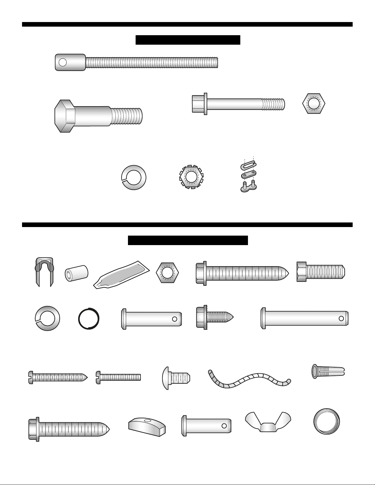
B5
ASSEMBLY HARDWARE
INSTALLATION HARDWARE
Threaded
B1
Trolley Shaft (1)
B7
C1
Insulated
Staples (30)
C2
Spacer (2)
Idler Bolt (1)
Lock Washer
3/8" (1)
C3
Rail Grease
B6
Bolt 1/4" - 20 x 1-3/4" (2)
B3
B2
Lock Nut
1/2" - 20 (2)
C4
Nut 5/16" - 18 (4)
Lag Screw
C8 C9
5/16"-18 x 1-7/8" (2)
Nut 3/8" (1)
B4
Master Link (2)
Hex Bolt
5/16"- 18 x 7/8" (4)
C5
Lock Washer
5/16" (7)
Screw
C12
6AB x 1-1/4" (2)
C18
C6
Ring
Fastener (3)
Lag Screw
5/16"- 9 x 1-5/8" (2)
C13
Screw 6-32 x 1" (2)
C7
Clevis Pin
5/16" x 1-1/4" (1)
C14
C20
NOTICE
Handle (not shown
actual size)
Carriage Bolts
1/4"-20 x 1/2" (2)
Self-Threading Screw
C10
1/4"-14 x 5/8" (2)
C19
C21
Clevis Pin
5/16" x 1" (1)
Rope
C16
Wing Nut
1/4 x 20 (2)
C11
Clevis Pin
5/16" x 1-1/2" (1)
C17
2-Conductor Bell Wire
White & White/Red
C15
Drywall
Anchors (2)
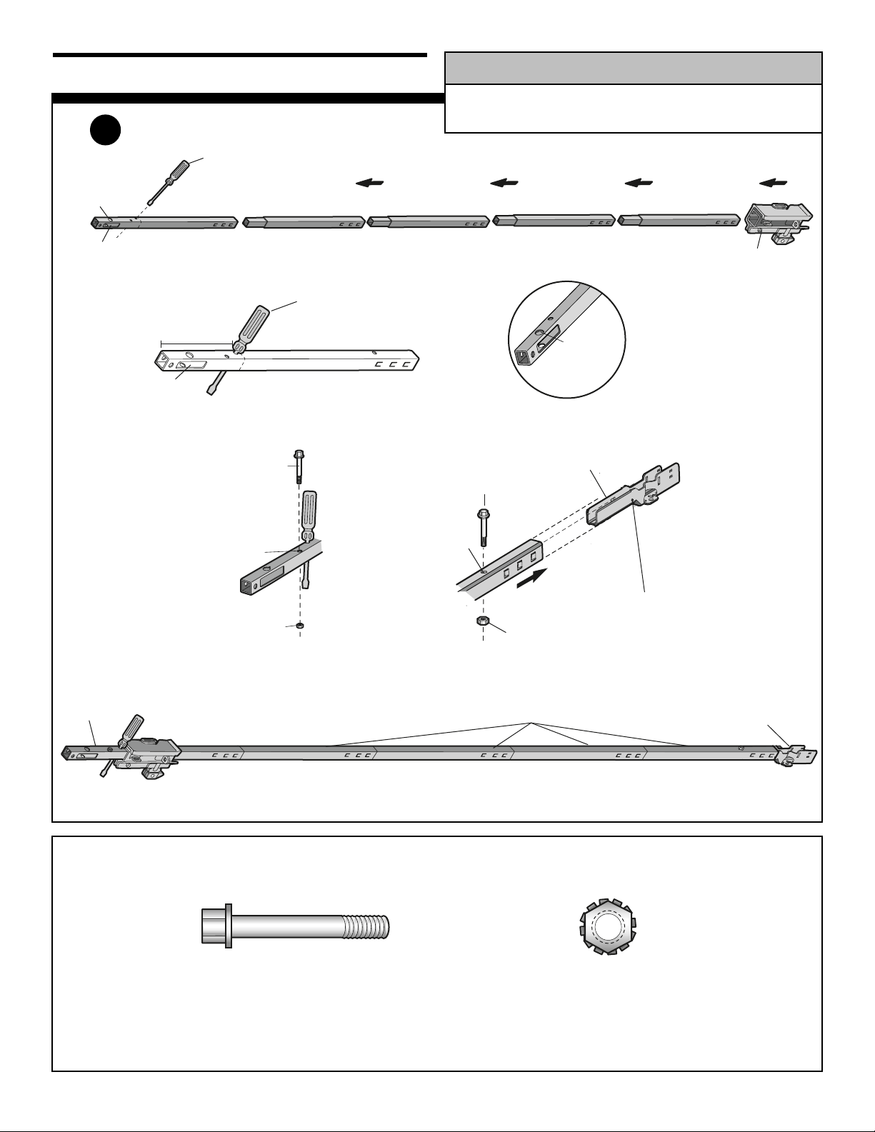
6
ASSEMBLY
Window
Cut-Out
Idler
Pulley
Hole
A13
A7
A7
A7
A7
A8
As a temporary trolley stop,
insert a screwdriver into the
hole 10" (25 cm) away from
the front of the rail, as shown.
Assemble the Rail
Front Rail
(TO DOOR)
Back Rails
(TO MOTOR UNIT)
A11 “U” Bracket
Window
Cut-Out
A8
10" (25 cm)
As a temporary trolley stop,
insert a screwdriver into the
hole 10" (25 cm) away from
the front of the rail, as shown.
To prevent INJURY from pinching, keep hands and fingers
away from the joints while assembling the rail.
WARNING
WARNING
WARNING
ALL HARDWARE SHOWN ACTUAL SIZE
1
B3 Lock Nut
Cover
Protection
Bolt Hole
B6 Bolt
A11 “U” Bracket
SLIDE RAIL TO STOPS
ON TOP AND SIDES
OF BRACKET
TO MOTOR UNIT
B6 Bolt
CAUTION
KEEP SMALL HOLES
ALONG OPPOSITE EDGE
OF RAILS
A8
KEEP LARGER
HOLE ON TOP
FRONT RAIL
(TOP)
Trolley
Stop Hole
B3 Lock Nut
B6 Bolt
B3 Lock Nut
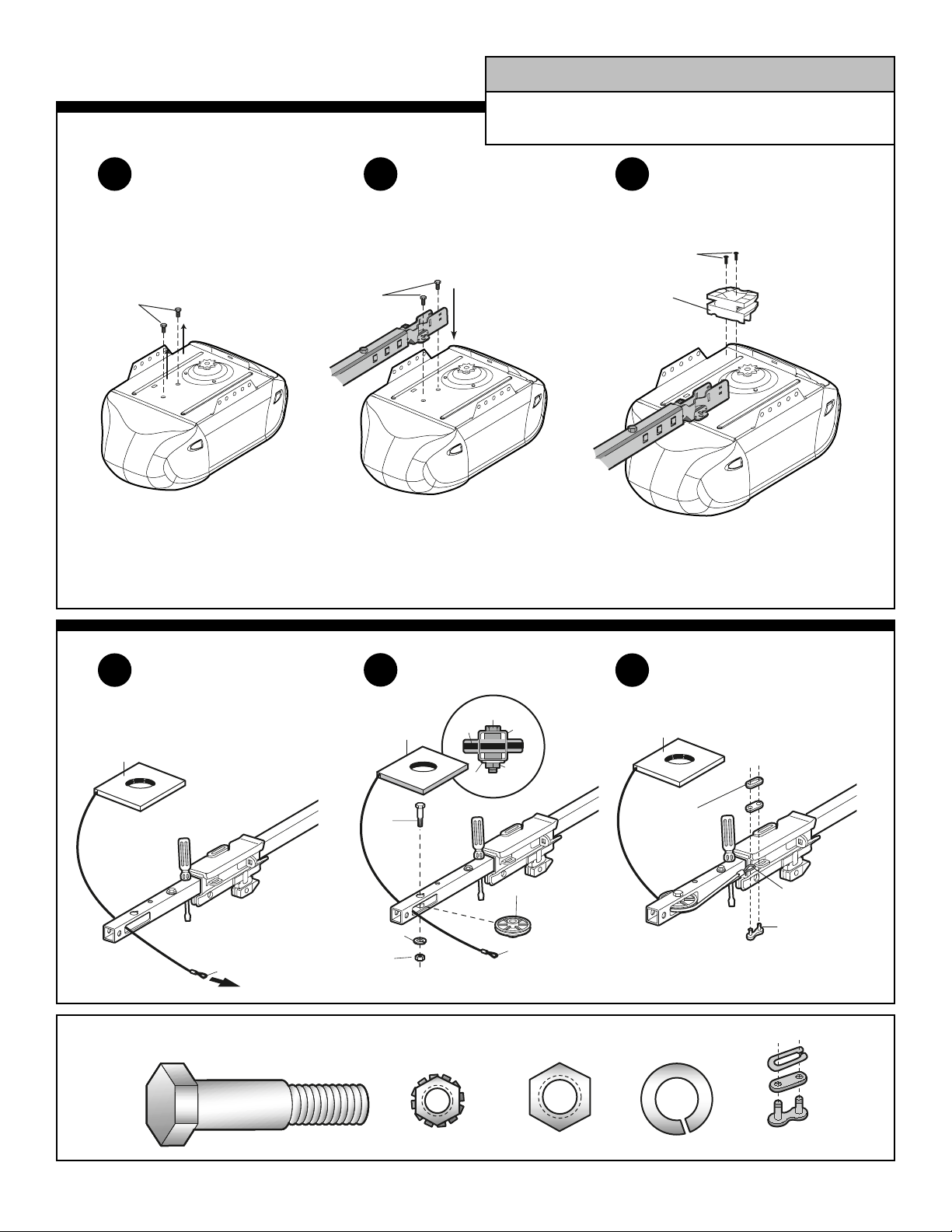
7
Attach Chain Spreader
ALL HARDWARE SHOWN ACTUAL SIZE
To avoid serious damage to opener, ONLY use bolts/fasteners
mounted in top of motor unit.
WARNING
CAUTION
WARNING
WARNING
Attach Cable to Front
of Trolley
Run Cable Through
Cut-Out Window
Install Idler Pulley
A3
Chain
Spreader
Bolt
Bolt
Hex Screws
8-32x7/16"
B7 Nut
B2 Lock Washer
B3 Lock Nut
B5 Idler Bolt
2
3 4
5
6
7
Remove Fasteners from
Top of Motor Unit
Attach Rail to Motor Unit
A2 Chain and Cable
Do NOT remove
Chain/Cable
from box
Cable Loop
A2
Chain
and Cable
B5
Idler Bolt
B2
Lock Washer
B7 Nut
Pulley
Washer
Bolt
Rail
Nut
A12 Idler Pulley
Cable Loop
A2 Chain and Cable
B4
Master Link
Clip-On Spring
Do NOT remove
Chain/Cable
from box
Cable
Loop
B4
Master
Link Bar
B4 Master Link
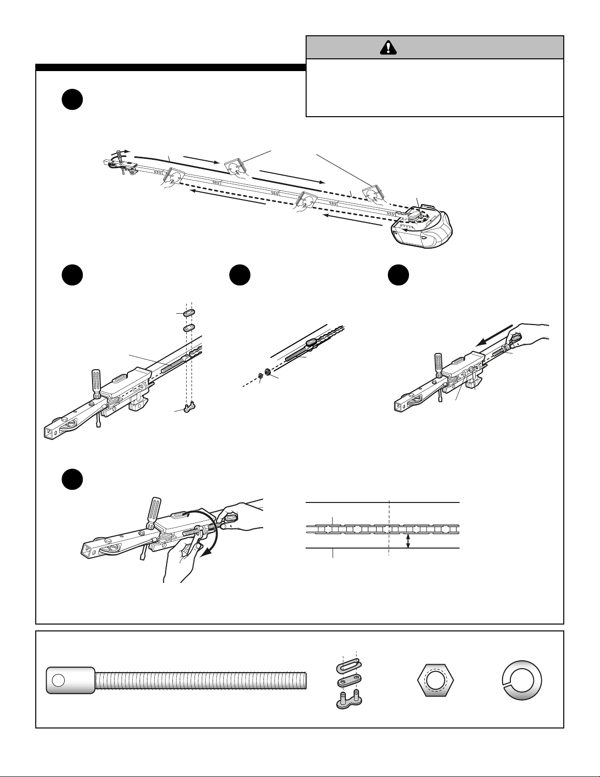
8
Cable
Chain
Motor Unit
Sprocket
A2
Chain and
Cable in
Dispensing
Carton
Leave chain/cable inside
carton to prevent kinking
B4
Master Link
Clip-On Spring
B1
Trolley
Threaded
Shaft
B4
Master
Link Bar
Attach Chain To Trolley
Threaded Shaft
Insert Trolley Threaded
Shaft into Round Hole in
Trolley
Attach Nut and Lock
Washer to Trolley
Threaded Shaft
Tighten the Chain
Desired Chain Tension
ALL HARDWARE SHOWN ACTUAL SIZE
To avoid possible SERIOUS INJURY to fingers:
• Securely attach chain spreader.
• NEVER connect garage door opener to power source until
instructed to do so.
WARNING
Route Chain/Cable Around Rail Assembly
and Motor Unit Sprocket
Assembly of your opener is now complete.
8
9
10 11
12
WARNING
B1
Trolley
Threaded
C5
Lock
Washer
C4
Inner Nut
Shaft
A2 Chain
C6
Lock Washer
C5
Outer Nut
1/4" (6 mm)
B1
Trolley
Threaded
Shaft
Base of Rail
Mid Length of Rail
B4 Master Link C4 Nut C5 Lock Washer B1 Threaded Trolley Shaft
If you have a sectional door, proceed to page 10
of this manual.
INSTALLATION
IMPORTANT INSTALLATION INSTRUCTIONS
To reduce the risk of SEVERE INJURY or DEATH:
WARNING
1. READ AND FOLLOW ALL INSTALLATION WARNINGS AND
INSTRUCTIONS.
2. Install garage door opener ONLY on properly balanced and
lubricated garage door. An improperly balanced door may not
reverse when required and could result in SEVERE INJURY or
DEATH.
3. ALL repairs to cables, spring assemblies and other hardware
MUST be made by a trained door systems technician BEFORE
installing opener.
4. Disable ALL locks and remove ALL ropes connected to garage
door BEFORE installing opener to avoid entanglement.
5. Install garage door opener 7 feet (2.13 m) or more above floor.
6. Mount emergency release handle 6 feet (1.83 m) above floor.
7. NEVER connect garage door opener to power source until
instructed to do so.
8. NEVER wear watches, rings or loose clothing while installing
or servicing opener. They could be caught in garage door or
opener mechanisms.
9. Install wall-mounted garage door control:
• within sight of the garage door
• out of reach of children at minimum height of 5 feet (1.5 m)
• away from ALL moving parts of the door.
10. Place entrapment warning label on wall next to garage door
control.
11. Place manual release/safety reverse test label in plain view on
inside of garage door.
12. Upon completion of installation, test safety reversal system.
Door MUST reverse on contact with a 1-1/2" high (3.8 cm)
object (or a 2 x 4 laid flat) on the floor.
9
If you have a one-piece door, proceed to the
One-Piece Door Installation Instructions included
with your garage door opener.
Sectional DoorOne-Piece Door
G
A
R
A
G
E
D
O
O
R
O
P
E
N
E
R
A
S
S
E
M
B
L
Y
/IN
S
T
A
L
L
A
T
IO
N
M
A
N
U
A
L
■
P
l
e
a
s
e
r
e
a
d
t
h
i
s
m
a
n
u
a
l
a
n
d
t
h
e
e
n
c
l
o
s
e
d
s
a
f
e
t
y
m
a
t
e
r
i
a
l
s
c
a
r
e
f
u
l
l
y
!
■
Fa
s
t
e
n
t
h
e
m
a
n
u
a
l
n
e
a
r
t
h
e
g
a
r
a
g
e
d
o
o
r
a
f
t
e
r
i
n
s
t
a
l
l
a
t
i
o
n
.
■
T
h
e
d
o
o
r
W
I
L
L
N
O
T
C
L
O
S
E
u
n
l
e
s
s
t
h
e
P
r
o
t
e
c
t
o
r
S
y
s
t
e
m
®
i
s
c
o
n
n
e
c
t
e
d
a
n
d
pr
o
pe
r
l
y
a
l
i
g
n
e
d
.
■
P
e
r
i
o
d
i
c
c
h
e
c
k
s
o
f
t
h
e
o
pe
n
e
r
a
r
e
r
eq
u
i
r
e
d
t
o
e
n
s
u
r
e
s
a
f
e
o
p
e
r
a
t
i
o
n
.
■
T
h
e
m
o
d
e
l
n
u
m
b
e
r
l
ab
e
l
i
s
l
o
c
a
t
e
d
u
n
d
e
r
t
h
e
l
ig
h
t
l
e
n
s
o
n
t
h
e
f
r
o
n
t
pa
n
e
l
o
f
y
o
u
r
o
p
e
n
e
r
.
W
h
e
n
y
o
u
s
e
e
t
h
e
s
e
S
a
f
e
t
y
S
y
m
b
o
ls
a
n
d
S
i
g
n
a
l
W
o
r
d
s
o
n
t
h
e
f
o
l
l
o
w
i
n
g
p
a
g
e
s
,
t
h
e
y
w
i
l
l
a
l
e
r
t
y
o
u
t
o
t
h
e
p
o
s
s
i
b
i
l
i
t
y
o
f
s
e
r
i
o
u
s
i
n
j
u
r
y
o
r
d
e
a
t
h
i
f
y
o
u
d
o
n
o
t
c
o
m
p
l
y
w
it
h
t
h
e
w
a
r
n
i
n
g
s
t
h
a
t
ac
c
o
m
p
a
n
y
t
h
e
m
.
Th
e
h
a
z
a
r
d
m
a
y
c
o
m
e
f
r
o
m
s
o
m
e
t
h
i
n
g
m
e
c
h
a
n
i
c
a
l
o
r
f
r
o
m
e
le
c
t
r
i
c
s
h
oc
k
.
R
e
a
d
t
h
e
w
a
r
n
i
n
g
s
c
a
r
e
f
u
l
l
y
.
W
h
e
n
y
o
u
s
e
e
t
h
i
s
S
i
g
n
a
l
W
o
r
d
o
n
t
h
e
f
o
l
l
o
w
i
n
g
p
a
g
e
s
,
i
t
w
i
l
l
a
l
e
r
t
y
o
u
t
o
t
h
e
p
o
s
s
i
b
il
i
t
y
o
f
d
a
m
a
g
e
t
o
y
o
u
r
g
a
r
a
g
e
d
o
o
r
a
n
d
/
o
r
t
h
e
g
a
r
a
g
e
d
o
o
r
o
p
e
n
e
r
i
f
y
o
u
d
o
n
o
t
c
o
m
p
l
y
w
i
t
h
t
h
e
c
a
u
t
i
o
n
a
r
y
s
t
a
t
e
m
e
n
t
s
t
h
a
t
ac
c
o
m
p
a
n
y
i
t
.
R
e
a
d
t
h
e
m
c
a
r
e
f
u
l
l
y
.
Me
c
h
a
n
i
c
a
l
E
l
e
c
t
r
i
c
a
l
W
W
A
R
N
ARN
I
NG
IN
G
C
AUTION
W
W
A
R
N
ARN
I
N
G
IN
G
W
AR
N
IN
G
C
A
U
T
IO
N
C
AUTION
Th
i
s
g
a
r
a
g
e
d
o
o
r
o
p
e
n
e
r
h
a
s
b
e
e
n
d
e
s
i
g
n
e
d
a
n
d
t
e
s
t
e
d
t
o
o
f
f
e
r
s
a
f
e
s
e
r
v
ic
e
p
r
o
v
i
d
e
d
it
is
in
s
t
a
l
l
e
d
,
o
p
e
r
a
t
e
d
,
m
a
i
n
t
a
i
n
e
d
a
n
d
t
e
s
t
e
d
in
s
t
r
i
c
t
ac
c
o
r
d
a
n
c
e
w
i
t
h
t
h
e
in
s
t
r
u
c
t
i
o
n
s
a
n
d
w
a
r
n
i
n
g
s
c
o
n
t
a
i
n
e
d
i
n
th
i
s
m
a
n
u
a
l
.
I
M
P
O
R
T
A
N
T
S
A
F
E
T
Y
N
O
T
E
S
PD
2
1
0
D
•
P
D
2
1
2
D
PD
6
1
0
D
•
PD
6
1
2
D
•
7
5
2
0
D
• P
D
6
1
2
K
LD
•
4
8
9
3
0
D
Th
e
C
h
a
m
b
e
r
l
a
i
n
Gr
o
u
p
,
I
n
c
.
8
4
5
L
a
r
c
h
A
v
e
n
u
e
E
l
m
h
u
r
s
t
,
I
l
l
i
n
o
i
s
6
0
1
2
6
1
1
9
6
w
w
w
.
c
h
a
m
b
e
r
l
a
i
n
.
c
o
m
T
h
e
r
e
a
r
e
t
w
o
t
y
p
e
s
o
f
g
a
r
a
g
e
d
o
o
r
o
p
e
n
e
r
s
p
i
c
t
u
r
e
d
.
Y
o
u
r
s
m
a
y
a
p
p
e
a
r
s
l
i
g
h
t
l
y
d
i
ff
e
r
e
n
t
.
INSTALLATION
INSTRUCTIONS
FOR ONE-PIECE
DOORS
PAGE 10
WARNING
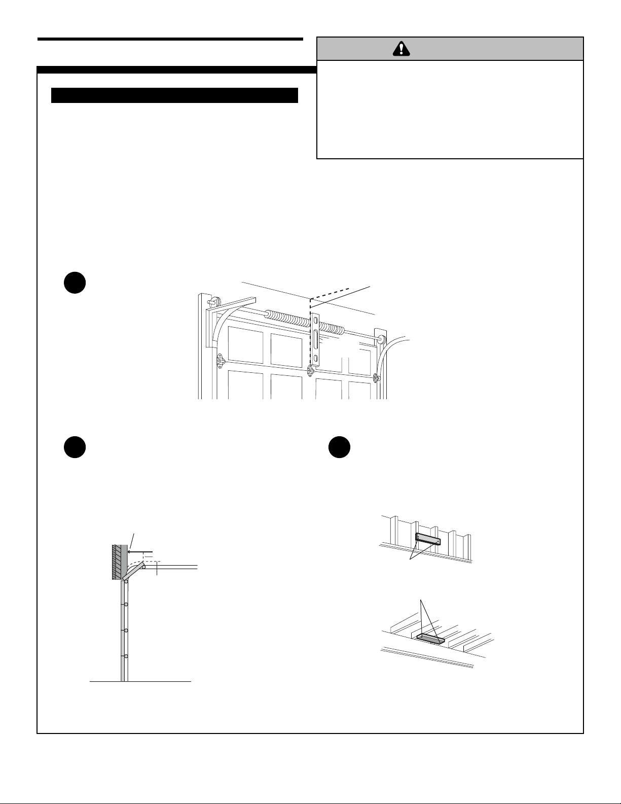
Add a 2 x 4 as a Structural Support
(If Necessary)
Highest Point
of Travel
2" (5 cm)
Mark a spot on the “center of the
garage door” line, 2" (5 cm) above the
highest point of travel of the garage door
Determine the Highest Point of
Travel, and Draw Horizontal Line
for Header Bracket Placement
NOTE: You can fasten the header bracket within 4 feet
(1.2 m) of the left or right of the door center only if a
torsion spring or center bearing plate is in the way; or
you can attach it to the ceiling when clearance is
minimal.
Fasten header bracket securely to structural supports.
It may be necessary to use a 2 x 4 as a structural
support if installing on drywall or between two studs as
shown in Step 3. Securely fasten 2 x 4 to structural
supports using lag screws (not provided). Concrete
anchors must be used if mounting header bracket or
2 x 4 into masonry.
To prevent possible SERIOUS INJURY or DEATH:
• Header bracket MUST be RIGIDLY fastened to structural
support on header wall or ceiling, otherwise garage door
might not reverse when required.
• NEVER try to loosen, move or adjust garage door, springs,
cables, pulleys, brackets, or their hardware, all of which are
under EXTREME tension.
WARNING
INSTALL THE HEADER BRACKET
a
Mark the center of the garage door on door
and wall and extend onto the ceiling
10
2
3
INSTALLATION
Mark the Center of the
Garage Door
1
WARNING
Level
(optional)
door, wall
-In some installations it may be
necessary to install a 2x4 across
two studs to create a location for
header bracket
-or over drywall
Use lag screws (not provided)
to secure 2x4 (structural support) into
wood. Use concrete anchors to secure 2x4
into masonry.
11
NOTE: If the door spring
is in the way, you’ll need
help. Have someone hold
the opener securely on a
temporary support to allow
the rail to clear the spring.
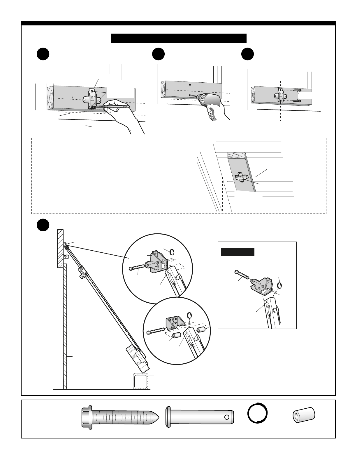
Attach Rail to the Header Bracket
Mark Bracket Holes Drill Holes
ALL HARDWARE
SHOWN
ACTUAL SIZE
Attach Bracket
MOUNT THE HEADER BRACKET
NOTE: If your installation requires that the
header bracket be mounted to the ceiling. The
back edge of the bracket MUST NOT be
further than 6" (15 cm) from the header wall
and the arrow MUST point away from the
header wall.
Ceiling Mount the Header Bracket (Optional)
C6 Ring Fastener
C2 Spacer
C11 Clevis Pin
C18 Lag Screw
4
5
6
7
Center bracket on the “center
of garage door” line and the
horizontal line made in Step 2.
Horizontal Line
Highest Point
of Travel
Center of
Garage Door
A14
Bracket
Mark the top
UP
and bottom
bracket holes
Drill two 3/16"
pilot holes
Secure bracket
with lag screws
U
P
A14
Bracket
Use holes on
left and right side
to secure bracket
U
P
C18
Center the bracket
on the “center of
garage door” line
Lag Screw
A14 Header Bracket
Garage
Door
A14
Header
Bracket
C11
Clevis Pin
C6
Ring Fastener
Mounting
Hole
Existing
Header Bracket
Existing
Clevis Pin
C2
Spacer
Opener Carton
Mounting
Hole
Ceiling Mount
C11
Clevis Pin
Option with
some pre-existing
installations
A14
Header
Bracket
Mounting
Hole
C6
Ring Fastener
 Loading...