

Page 1

Power 100/120 User
Guide
Sections on Hard Disk ToolKit
and
CD-ROM ToolKit are Missing. :-(
Information on these products can be found
in the
Storage Device Training Module.
Part number 72771
Rev. number 951006
Page 2

Power Computing Corporation
1995 Power Computing Corporation. All rights reserved.
Under copyright laws, this manual may not be copied, in whole or in part, without the written consent of
Power Computing. Your rights to the software are governed by the accompanying software license
agreement.
Power Computing Corporation
10261 Bubb Road
Cupertino, CA 95014
(408) 725-7250
Power Computing is a trademark of Power Computing Corporation. Mac and the Mac OS logo are
trademarks of Apple Computer, Inc. All other trademarks mentioned are the property of their respective
holders. Every effort has been made in this book to distinguish proprietary trademarks from descriptive
terms by following the capitalization style used by the manufacturer.
Every effort has been made to ensure that the information in this manual is accurate. Power Computing
is not responsible for printing or clerical errors.
Other legal notices are found in
Manual Revision 951006
ÒRegulatory InformationÓ on page 65
Support Numbers
Please use the following numbers to contact Power Computing for assistance: (All times are Central
Standard Time.)
Sales
Customer
Support
To place or check on an
order you havenÕt
received yet
If you have a question or
a problem with an order
you have received
M Ð F 8AM to10 PM
Sat 9 AM to 6 PM
Sun 10 AM to 6 PM
M Ð F 8 AM to 6 PM 1-800-671-6227
1-800-999-7279
Technical
Support
For help with a technical
problem
M Ð F 8 AM to 8 PM
Sat 10 AM to 4 PM
1-800-708-6227
Page 3

Contents
Power 100/120 User Guide
Power 100/120 Overview ix
Desktop System Front View ix
Desktop System Rear View x
Tower System Front View xi
Tower System Rear View xii
A word from the Power Computing team xiii
Apple Computer, Inc. System Software License Agreement xv
Chapter 1
Getting Started
Finding a place for the computer and monitor 1
Plugging in the computer 2
Connecting the monitor 4
Connecting the mouse and keyboard 6
Turning the computer on 8
Chapter 2
Getting Started With Mac OS
Running the Basics tutorial 9
Using on-line help 10
Shutting down 11
Chapter 3
Upgrading Your Computer
Removing the cover 13
Installing expansion cards 17
Switching video ports 20
Increasing memory 21
Increasing VRAM 27
Installing internal drives 28
Power 100/120 User Guide
iii
Page 4

Chapter 4
Connecting Peripheral Devices
Using SCSI devices 41
Connecting a printer 43
Connecting input devices 44
Connecting a modem or telecom adapter 45
Connecting to a network 45
Using audio equipment 46
Appendix A
Safety and Health Information
Safety instructions 49
Health-related information about computer use 49
Appendix B
Troubleshooting
Restarting the computer 51
Problems and solutions 52
Contacting Technical Support 55
Appendix C
Installing System Software
Starting up 57
Reinstalling system software 58
Appendix D
Technical Information
SpeciÞcations 59
RAM conÞgurations 61
VRAM conÞgurations 62
Power requirements 63
Appendix E
Regulatory Information
FCC statement 65
DOC statement 66
CD-ROM drive 67
Lithium battery warning 67
For use in European countries 67
iv
Power 100/120 User Guide
Page 5

Hard Disk ToolKit¥
Personal Edition
User Guide
Hard Disk ToolKit¥Personal Edition End-User
Software License Agreement 71
Hard Disk ToolKit¥Personal Edition 73
Copyright Notice 73
Trademarks 73
Disclaimer of Liability and Warranty 73
Introduction 75
Welcome to Hard Disk ToolKit¥
System Requirements 75
What Is Hard Disk ToolKit¥
Installing Hard Disk ToolKit¥
Installing Hard Disk ToolKit¥Personal Edition 79
Check your hard disk to double-check the Installation process (optional) 83
Creating an HDT Primer PE Startup diskette 85
Creating a Startup Disk 85
Personalizing your copy of Hard Disk Toolkit¥Personal Edition 87
Personal Edition 75
Personal Edition
? 75
Personal Edition 79
HDT Primer PE 89
What is HDT Primer PE? 89
The HDT Driver 90
Using HDT Primer PE 91
Launching HDT Primer PE 92
Formatting 94
Initializing 97
Partitioning 99
Testing a Drive 106
Information Capabilities 107
HDT Primer PE Menu Commands 110
Apple Menu 110
File Menu 110
Edit Menu 111
SCSI Bus menu 112
HDT Extension 113
What is HDT Extension? 113
Important information regarding HDT Extension 113
HDT Extension 114
Power 100/120 User Guide
v
Page 6

HDT Prober 115
Using HDT Prober 116
Drive Information 118
Mounting a Drive 118
Device Driver Installed 118
HDT Prober Õpower user Õ keys: 119
HDT Util 121
HDT Util: for System 6 users only 121
The HDT Util menu commands 121
Troubleshooting 125
Common problems by category 125
ToolKit Operation Problems 125
Happy Mac Problems 126
Sad Mac 126
Drive Problems 127
Removable Media 129
File-Oriented Problems 129
System Bomb 130
Turning off Blind transfers 131
Frequently asked questions 132
CD-ROM ToolKit User Guide
Introduction 149
Before You Begin 149
What is CD-ROM? 150
Why CD-ROM ToolKit? 150
Registration 151
Hardware and Software Requirements 151
Removing Old Driver Software 152
QuickStart 154
Basic Installation 154
Personalizing CD-ROM ToolKit 157
Installation and Removal Specifics 158
Installing CD-ROM ToolKit 158
Removing CD-ROM ToolKit 160
Instruction Guide 162
The CD-ROM ToolKit Control Panel 162
Reading Different CD-ROM Formats 170
Photo CD discs 171
Prescanning CDs for Acceleration 173
Playing Audio Discs with CDT Remote 174
Using CDT Remote 175
vi
Power 100/120 User Guide
Page 7

Troubleshooting 179
CD-ROM ToolKit Q & A 179
Technical Information and Tips 192
Care of Manual Ejecting CD-ROM Drives 192
CD Recorders 192
All About Multisession Multi-Volume CD-ROMs 193
All about Digital Audio Extraction 196
What is an AIFF Þle? 200
Glossary 205
Bitstream Typeface Library 211
Index 215
Registration Cards 223
Power 100/120 User Guide
vii
Page 8

viii
Power 100/120 User Guide
Page 9
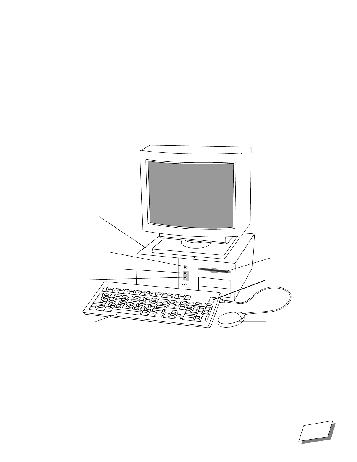
Power 100/120 Overview
Desktop System Front View
Here are the key features of the desktop system front panel.
Monitor
Computer
0
Front panel
power button
ProgrammerÕs
(Interrupt) button
Reset
button
Keyboard
Floppy
disk
drive
Keyboard
power
key
Mouse
For Technical Support, Call 1-800-708-6227
Power 100/120 User Guide
ix
Page 10
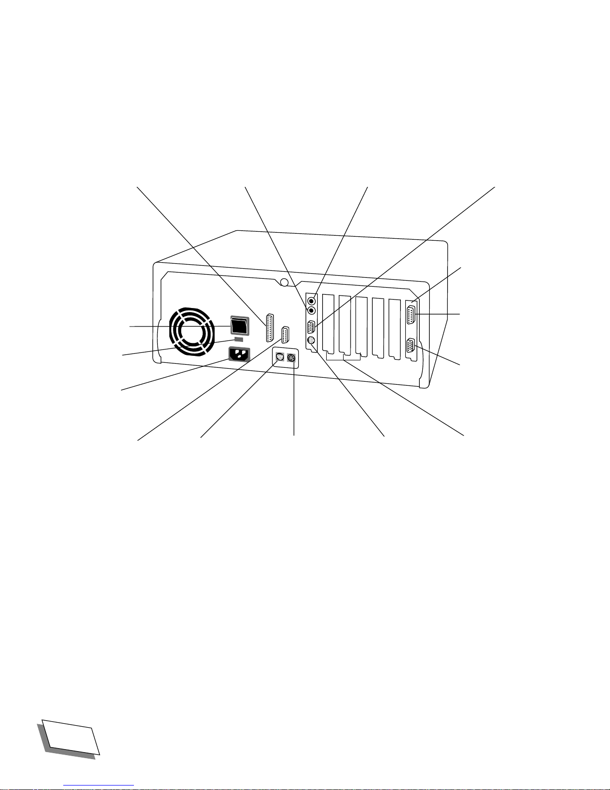
Desktop System Rear View
Here are the key components of the desktop system rear panel.
g SCSI port - Sound out port G Ethernet portX Sound in port
Optional highperformance
video card with
Main power
switch
115/230 volt
switch
Power cord
socket
DRAM video
monitor port
(Mac-standard)
Macintosh-
I
0
standard monitor
port and
VGA port
[ Printer port V ADB port W Modem port NuBus expansion
slots
x
Power 100/120 User Guide
For Technical Support, Call 1-800-708-6227
Page 11
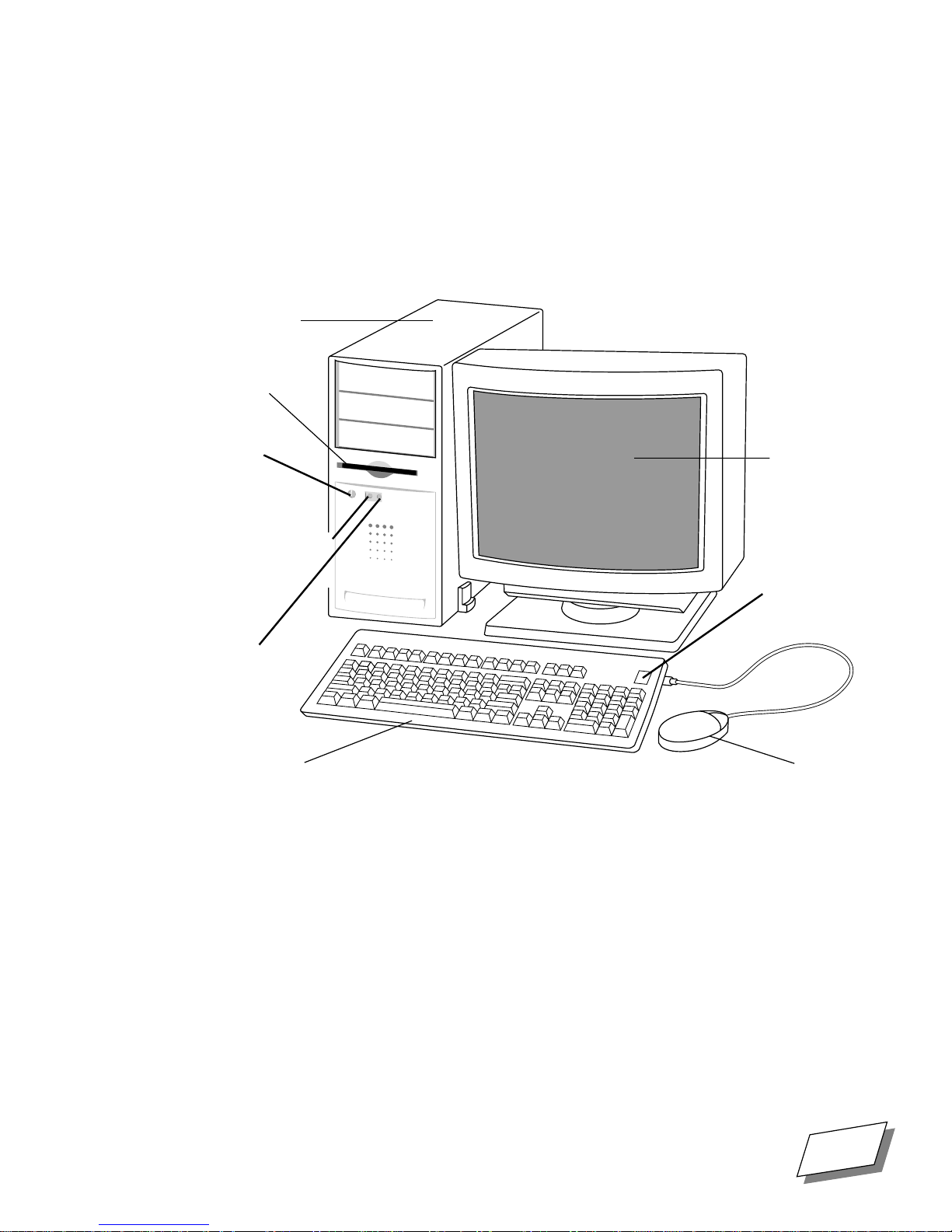
Tower System Front View
Here are the key features of the tower system front panel.
Computer
Floppy
disk
drive
Front
panel
power
button
ProgrammerÕs(I
nterrupt) button
Reset
button
Keyboard
Monitor
Keyboard
power
key
Mouse
For Technical Support, Call 1-800-708-6227
Power 100/120 User Guide
xi
Page 12
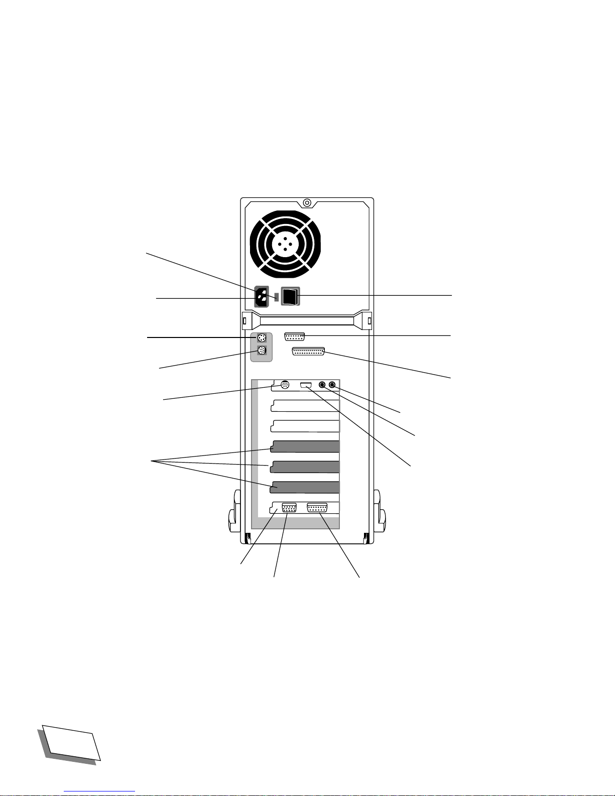
Tower System Rear View
Here are the key components of the tower system rear panel.
115/230 volt
switch
Power cord
socket
[ Printer
port
V ADB port
W Modem port
NuBus
expansion
slots
Optional highperformance
video card with
I
0
Main power
switch
DRAM video
monitor port (Mac
standard)
g SCSI port
- Sound out port
X Sound in port
G Ethernet port
VGA port and Macintosh-standard monitor port
xii
Power 100/120 User Guide
For Technical Support, Call 1-800-708-6227
Page 13

A word from the Power
Computing team
Dear New Power Computer Owner,
Thank you for choosing this Mac OS compatible computer from Power Computing Corporation. We
appreciate your support. As the new kids on the block, so to speak, weÕve got something to prove. We
think that Ñ dollar for dollar and pound for pound Ñ Power Computing builds the best Mac OS
compatible computers in the world. So thank you for giving us this opportunity to prove it to you.
Unlike some companies, we want to hear from you. Really. Give us a call anytime (or send us e-mail at
suggestionbox@powercc.com
LeVitus, the popular author, columnist, and industry pundit; he wants to hear what you have to say about
our products (heÕs at extension 3213 or send him e-mail at
Even if you donÕt call us, a Power Computing Corporation representative will be contacting
next few days to make sure that everything is working to your satisfaction. In the meantime, donÕt
hesitate to let us know if there is anything else we can do for you. And please, if thereÕs something we
could have done better, let us know that, too! Our company charter is to exceed your expectations in
every way. Nothing less will do.
); no question is too big or small. Our Director of Evangelism is Bob
levitus@powercc.com
).
you
in the
0
Enjoy your new Power Computer.
Sincerely,
The Power Computing Team
For Technical Support, Call 1-800-708-6227
Power 100/120 User Guide
xiii
Page 14

xiv
Power 100/120 User Guide
For Technical Support, Call 1-800-708-6227
Page 15

Apple Computer, Inc. System Software License Agreement
PLEASE READ THIS LICENSE CAREFULLY BEFORE USING THE SOFTWARE. BY USING
THE SOFTWARE, YOU ARE AGREEING TO BE BOUND BY THE TERMS OF THIS LICENSE.
IF YOU DO NOT AGREE TO THE TERMS OF THIS LICENSE, PROMPTLY RETURN THE UNUSED SOFTWARE TO THE PLACE WHERE YOU OBTAINED IT AND YOUR MONEY WILL BE
REFUNDED.
0
1. License.
The application, demonstration, system and other software accompanying this License,
whether on disk, in read only memory, or on any other media (the ÒApple SoftwareÓ), the related documentation and fonts are licensed to you by Apple. You own the disk on which the Apple Software and
fonts are recorded but Apple and/or Apple's Licensor(s) retain title to the Apple Software, related documentation and fonts. This License allows you to use the Apple Software and fonts on a single Apple computer and make one copy of the Apple Software and fonts in machine-readable form for backup purposes
only. You must reproduce on such copy the Apple copyright notice and any other proprietary legends
that were on the original copy of the Apple Software and fonts. You may use the Apple Software in a
networked environment so long as each computer in such environment is the subject of a license for the
Apple Software; however, you many not electronically transmit the Apple Software from one computer
to another over a network. You may also transfer all your license rights in the Apple Software and fonts,
the backup copy of the Apple Software and fonts, the related documentation and a copy of this License
to another party, provided the other party reads and agrees to accept the terms and conditions of this License.
2. Restrictions.
The Apple Software contains copyrighted material, trade secrets and other proprietary
material and in order to protect them you may not decompile, reverse engineer, disassemble or otherwise
reduce the Apple Software to a human-perceivable form. You may not modify, network, rent, lease,
loan, distribute or create derivative works based upon the Apple Software in whole or in part, except for
the limited networking described above in Section 1. THIS APPLE SOFTWARE MAY NOT BE IMPORTED TO, USED IN, OR RE-EXPORTED FROM FRANCE OR ANY OF ITS COLONIES OR
TERRITORIES.
3. Termination.
This License is effective until terminated. You may terminate this License at any time
by destroying the Apple Software, related documentation and fonts and all copies thereof. This License
will terminate immediately without notice from Apple if you fail to comply with any provision of this
License. Upon termination you must destroy the Apple Software, related documentation and fonts and
all copies thereof.
4. Export Law Assurances.
You agree and certify that neither the Apple Software nor any other technical data received from Apple, nor the direct product thereof, will be exported outside the United States
except as authorized and as permitted by the laws and regulations of the United States. If the Apple Software has been rightfully obtained by you outside of the United States, you agree that you will not reexport the Apple Software nor any other technical data received from Apple, nor the direct product thereof, except as permitted by the laws and regulations of the United States and the laws and regulations of
the jurisdiction in which you obtained the Apple Software.
5. Government End Users.
For Technical Support, Call 1-800-708-6227
If you are acquiring the Apple Software and fonts on behalf of any unit or
Power 100/120 User Guide
xv
Page 16

agency of the United States Government, the following provisions apply. The Government agrees:
(i) if the Apple Software and fonts are supplied to the Department of Defense (DoD), the Apple
Software and fonts are classified as ÒCommercial Computer SoftwareÓ and the Government is acquiring
only Òrestricted rightsÓ in the Apple Software, its documentation and fonts as that term is defined in
Clause 252.227-7013(c)(1) of the DFARS; and
(ii) if the Apple Software and fonts are supplied to any unit or agency of the United States Government other than DoD, the Government's rights in the Apple Software, its documentation and fonts will
be as defined in Clause 52.227-19(c)(2) of the FAR or, in the case of NASA, in Clause 18-52.227-86(d)
of the NASA Supplement to the FAR.
6. Limited Warranty on Media.
Apple warrants the diskettes and/or compact disc on which the Apple
Software and fonts are recorded to be free from defects in materials and workmanship under normal use
for a period of ninety (90) days from the date of purchase as evidenced by a copy of the receipt. Apple's
entire liability and your exclusive remedy will be replacement of the diskettes and/or compact disc not
meeting Apple's limited warranty and which is returned to Apple or an Apple authorized representative
with a copy of the receipt. Apple will have no responsibility to replace a disk/disc damaged by accident,
abuse or misapplication. ANY IMPLIED WARRANTIES ON THE DISKETTES AND/OR COMPACT DISC, INCLUDING THE IMPLIED WARRANTIES OF MERCHANTABILITY AND FITNESS FOR A PARTICULAR PURPOSE, ARE LIMITED IN DURATION TO NINETY (90) DAYS
FROM THE DATE OF DELIVERY. THIS WARRANTY GIVES YOU SPECIFIC LEGAL RIGHTS,
AND YOU MAY ALSO HAVE OTHER RIGHTS WHICH VARY BY JURISDICTION.
7. Disclaimer of Warranty on Apple Software.
You expressly acknowledge and agree that use of the
Apple Software and fonts is at your sole risk. The Apple Software, related documentation and fonts are
provided ÒAS ISÓ and without warranty of any kind and Apple and Apple's Licensor(s) (for the purposes
of provisions 7 and 8, Apple and Apple's Licensor(s) shall be collectively referred to as ÒAppleÓ) EXPRESSLY DISCLAIM ALL WARRANTIES, EXPRESS OR IMPLIED, INCLUDING, BUT NOT
LIMITED TO, THE IMPLIED WARRANTIES OF MERCHANTABILITY AND FITNESS FOR A
PARTICULAR PURPOSE. APPLE DOES NOT WARRANT THAT THE FUNCTIONS CONTAINED IN THE APPLE SOFTWARE WILL MEET YOUR REQUIREMENTS, OR THAT THE OPERATION OF THE APPLE SOFTWARE WILL BE UNINTERRUPTED OR ERROR-FREE, OR
THAT DEFECTS IN THE APPLE SOFTWARE AND THE FONTS WILL BE CORRECTED. FURTHERMORE, APPLE DOES NOT WARRANT OR MAKE ANY REPRESENTATIONS REGARDING THE USE OR THE RESULTS OF THE USE OF THE APPLE SOFTWARE AND FONTS OR
RELATED DOCUMENTATION IN TERMS OF THEIR CORRECTNESS, ACCURACY, RELIABILITY, OR OTHERWISE. WITHOUT PREJUDICE TO THE GENERALITY OF THE FOREGOING, APPLE DOES NOT WARRANT OR MAKE ANY REPRESENTATION OR GUARANTEE
REGARDING THE AUTHENTICITY OR SECURITY OF ANY DIGITAL SIGNATURE GENERATED USING THE APPLE SOFTWARE, OR ANY WARRANTY OR REPRESENTATION THAT THE
PERSON OR ENTITY THAT IS USING SUCH A DIGITAL SIGNATURE HAS THE AUTHORITY
TO DO SO. NO ORAL OR WRITTEN INFORMATION OR ADVICE GIVEN BY APPLE OR AN
APPLE AUTHORIZED REPRESENTATIVE SHALL CREATE A WARRANTY OR IN ANY WAY
INCREASE THE SCOPE OF THIS WARRANTY. SHOULD THE APPLE SOFTWARE PROVE DEFECTIVE, YOU (AND NOT APPLE OR AN APPLE AUTHORIZED REPRESENTATIVE) ASSUME
xvi
Power 100/120 User Guide
For Technical Support, Call 1-800-708-6227
Page 17

THE ENTIRE COST OF ALL NECESSARY SERVICING, REPAIR OR CORRECTION. SOME JURISDICTIONS DO NOT ALLOW THE EXCLUSION OF IMPLIED WARRANTIES, SO THE
ABOVE EXCLUSION MAY NOT APPLY TO YOU.
8. Limitation of Liability.
UNDER NO CIRCUMSTANCES INCLUDING NEGLIGENCE, SHALL
APPLE BE LIABLE FOR ANY INCIDENTAL, SPECIAL OR CONSEQUENTIAL DAMAGES
THAT RESULT FROM THE USE, INCLUDING BUT NOT LIMITED TO THE IMPROPER,
WRONGFUL, OR FRAUDULENT USE OF THE DIGITAL SIGNATURES GENERATED USING
THE APPLE SOFTWARE, OR INABILITY TO USE THE APPLE SOFTWARE OR RELATED DOCUMENTATION, EVEN IF APPLE OR AN APPLE AUTHORIZED REPRESENTATIVE HAS BEEN
ADVISED OF THE POSSIBILITY OF SUCH DAMAGES. SOME JURISDICTIONS DO NOT ALLOW THE LIMITATION OR EXCLUSION OF LIABILITY FOR INCIDENTAL OR CONSEQUENTIAL DAMAGES SO THE ABOVE LIMITATION OR EXCLUSION MAY NOT APPLY TO YOU.
In no event shall Apple's total liability to you for all damages, losses, and causes of action (whether in
contract, tort (including negligence) or otherwise) exceed the amount paid by you for the Apple Software
and fonts.
9. Controlling Law and Severability.
This License shall be governed by and construed in accordance
with the laws of the United States and the State of California, as applied to agreements entered into and
to be performed entirely within California between California residents. If for any reason a court of competent jurisdiction finds any provision of this License, or portion thereof, to be unenforceable, that provision of the License shall be enforced to the maximum extent permissible so as to effect the intent of the
parties, and the remainder of this License shall continue in full force and effect.
10. Complete Agreement.
This License constitutes the entire agreement between the parties with respect to the use of the Apple Software, related documentation and fonts, and supersedes all prior or contemporaneous understandings or agreements, written or oral, regarding such subject matter. No
amendment to or modification of this License will be binding unless in writing and signed by a duly authorized representative of Apple.
Note:
For Technical Support, Call 1-800-708-6227
The Apple Software Registration Card is in the back of the manual.
Power 100/120 User Guide
xvii
Page 18

xviii
Power 100/120 User Guide
For Technical Support, Call 1-800-708-6227
Page 19

Chapter
1
Your computer has been designed for easy plug-and-play setup in four simple steps - if you are in need of
technical assistance, please feel free to call Power Computing Technical Support at 1-800-708-6227.
Getting Started
1
Note:
system.
■
■
■
■
This manual covers both desktop and tower systems, so look for the illustration that Þts your
Find a place for the computer and monitor
Plug in the computer
Connect the monitor
Connect the mouse and keyboard
Finding a place for the computer and monitor
Think carefully about where you place your computer and monitor. Here are some suggestions to help
you Þnd a good place:
■
Make sure there is a grounded, three-hole electrical outlet within a few feet.
■
Use a sturdy, level table or desk as a work surface. Make sure that you can place your monitor,
keyboard, and mouse so that you can work comfortably. See
Information,Ó on page 49
■
You can place monitors up to 132 lb. (60 kg) on top of the desktop computer. If you have a heavier
monitor or a tower system, place the monitor directly on your work surface.
for detailed instructions.
Appendix A, ÒSafety and Health
■
Leave a few inches of space around the computer and monitor for air to circulate.
For Technical Support, Call 1-800-708-6227
Power 100/120 User Guide
1
Page 20
Getting Started
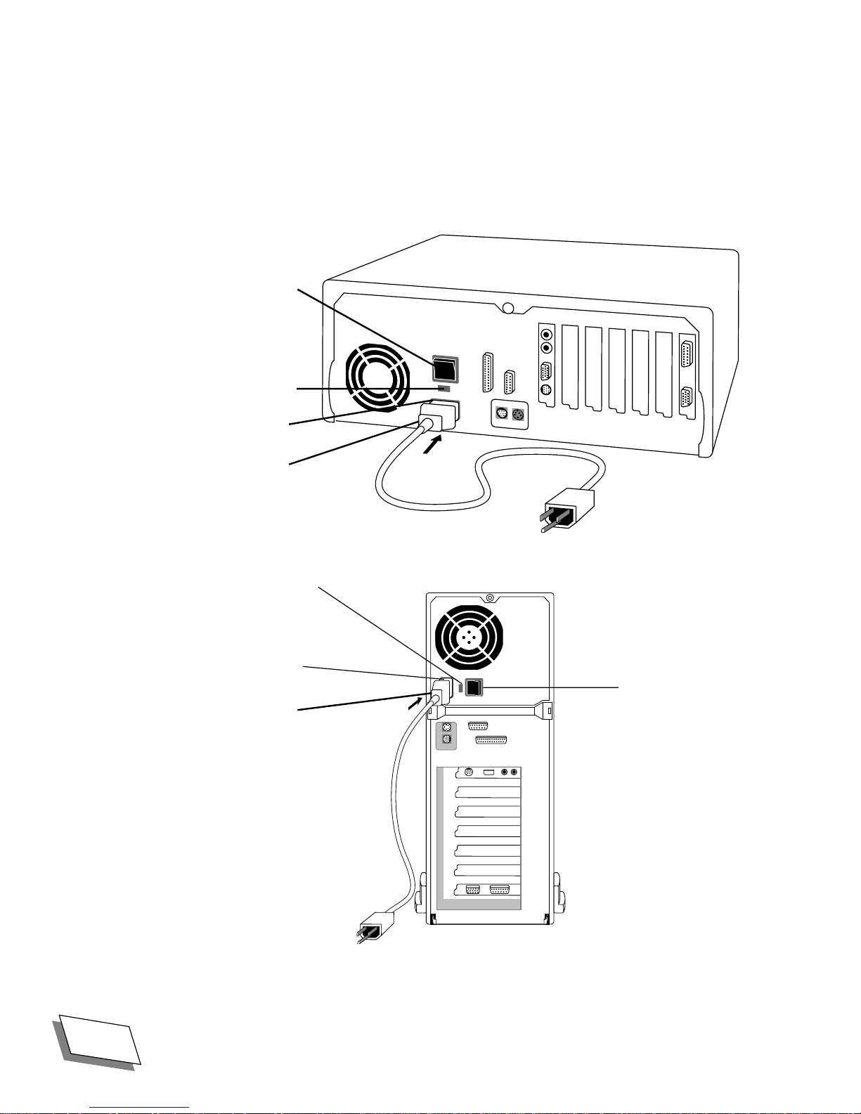
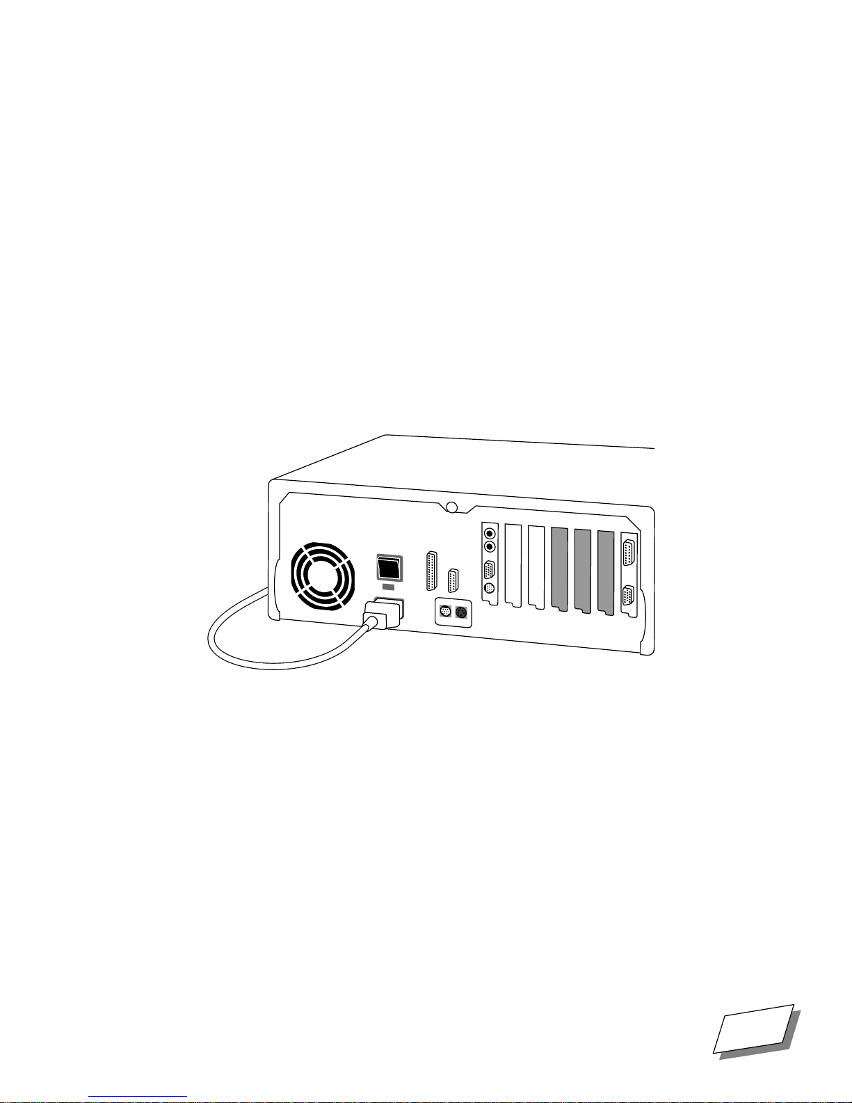
Plugging in the computer
Set up and plug in the computer before connecting the monitor, keyboard, and other devices. Plugging
in the computer ensures that it is grounded and protected from electrical damage. The key components
for plugging in the computer are shown below.
Main
power switch
115/230 volt
switch
Power cord
socket
Power cord
I
0
115/230 volt
switch
Power cord
socket
Power cord
I
0
Main power switch
2
Power 100/120 User Guide
For Technical Support, Call 1-800-708-6227
Page 21

Getting Started
WARNING!
For your safety, the computer is equipped with a three-prong plug
designed to be used with a grounded electrical outlet. If you do not have
access to an appropriate outlet, have an electrician install one. Do not use
your computer with a three-prong adapter in an ungrounded outlet.
To plug in the computer:
1.
Place the computer in the location you have chosen.
2.
Make sure the computerÕs main power switch is turned off.
The main power switch is located on the back of the computer. The power is off when the side of the
switch marked with is depressed.
3.
Set the 115/230 volt switch to the correct setting for your country.
Set the switch to 115 volts for the U.S., Canada, and Japan. Use the 230-volt setting in most European
countries.
4.
Connect the socket end of the power cord to the power plug on the back of
the computer.
5.
Plug the other end of the power cord into a grounded, three-hole electrical
outlet. If you have any expansion cards, follow the instructions in See
ÒInstalling expansion cardsÓ on page 17. to install them now. If not,
continue with the following section.
For Technical Support, Call 1-800-708-6227
Power 100/120 User Guide
3
Page 22
Getting Started
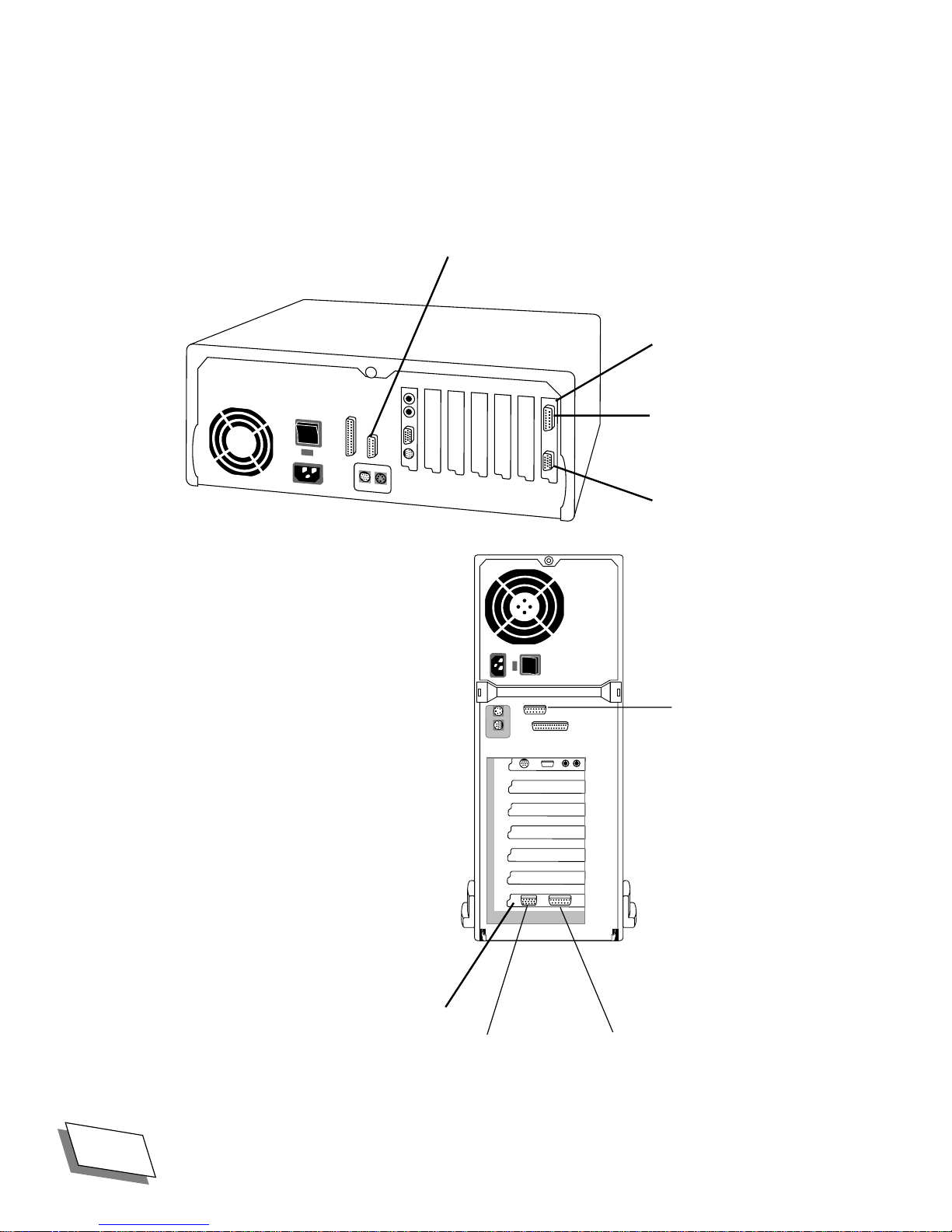
Connecting the monitor
Your computer can be used with a wide variety of monitors. It has one built-in standard monitor port,
with two additional monitor ports on the optional high-performance video card. The key components
for connecting the monitor are shown below.
DRAM video monitor port
(Mac-standard)
Optional highperformance
video card with
I
0
Macintoshstandard monitor
port and
VGA port
I
0
DRAM video
monitor port (Macstandard)
Optional highperformance
video card with
4
Power 100/120 User Guide
VGA port and Macintosh-standard monitor port
For Technical Support, Call 1-800-708-6227
Page 23

Getting Started
■
The DRAM video monitor port lets you connect 16-inch and smaller monitors and display thousands
of colors. This port requires Macintosh-style connectors or adapters.
■
The Macintosh-standard monitor port on the optional high-performance video card lets you connect
monitors of up to 21 inches in size and display millions of colors (depending on the amount of video
memory installed). This port requires Macintosh-style connectors or adapters.
■
The VGA monitor port on the optional high-performance video card allows you to connect a
standard VGA or SVGA monitor and use PC-style connectors.
See Appendix D, ÒTechnical InformationÓ for additional details on RAM conÞgurations, screen size
support and numbers of colors supported. You can add additional video memory ( VRAM) to increase the
number of colors available to monitors connected to the high-performance ports. See
memoryÓ on page 21
The high-performance ports are located on the high-performance video card in the computer. A switch
on the card enables the port you want. When the computer comes from the factory, the Macintosh
standard port is enabled. If this is the Þrst time the computer has been set up and you want to connect to
the Macintosh standard port, you do not need to make any changes. If you want to connect to the VGA
port on the high-performance video card, you must change the switch setting. See
portsÓ on page 20
for information about VRAM expansion.
for instructions.
ÒIncreasing
ÒSwitching video
You can connect two monitors at once, one to the standard monitor port and another to one of the highperformance monitor ports, however you cannot connect two monitors to the high-performance video
card. Use the Monitors control panel in Mac OS to control how the monitors are conÞgured. See
Macintosh Guide (available through the Guide menu, marked with ) or
Dummies
Connecting the monitor involves two steps: plugging in the monitor and connecting the monitor cable.
for additional information about using the Monitors control panel.
Macintosh System 7.5 for
To plug in the monitor:
1.
Place the monitor on your desk or in another location you have chosen.
2.
If necessary, connect the power cord to the monitor.
Some monitors have permanently attached power cords.
3.
Plug the monitor power cord into a grounded, three-hole outlet.
To connect the video cable:
1.
If necessary, attach the video cable to the monitor.
Some video cables are permanently attached.
For Technical Support, Call 1-800-708-6227
Power 100/120 User Guide
5
Page 24

Getting Started
2.
Connect the video cable to the monitor port on the back of the computer.
Depending on which type of monitor you use, connect it to one of the high-performance ports or to
the standard port. See
If you are connecting to a high-performance port, make sure that the correct port is enabled. See
ÒSwitching video portsÓ on page 20
3.
If you your computer is a Power 120, install the EMI choke on the video
cable.
The EMI choke is a small donut-shaped object which comes packed in the pizza box with the
manuals and cables.
To install the choke, open it up and clamp it over the video cable at the end of the cable that
connects to the computer.
ÒMonitor resolution/color tablesÓ on page 62
for instructions.
Connecting the mouse and keyboard
Once you have connected the monitor, you can connect the mouse and keyboard.
for more information.
To connect the mouse and keyboard:
1.
Plug the mouse cable into an ADB port (marked with V
The location of the ADB port depends on the keyboard you use.
) on the keyboard.
6
Power 100/120 User Guide
For Technical Support, Call 1-800-708-6227
Page 25
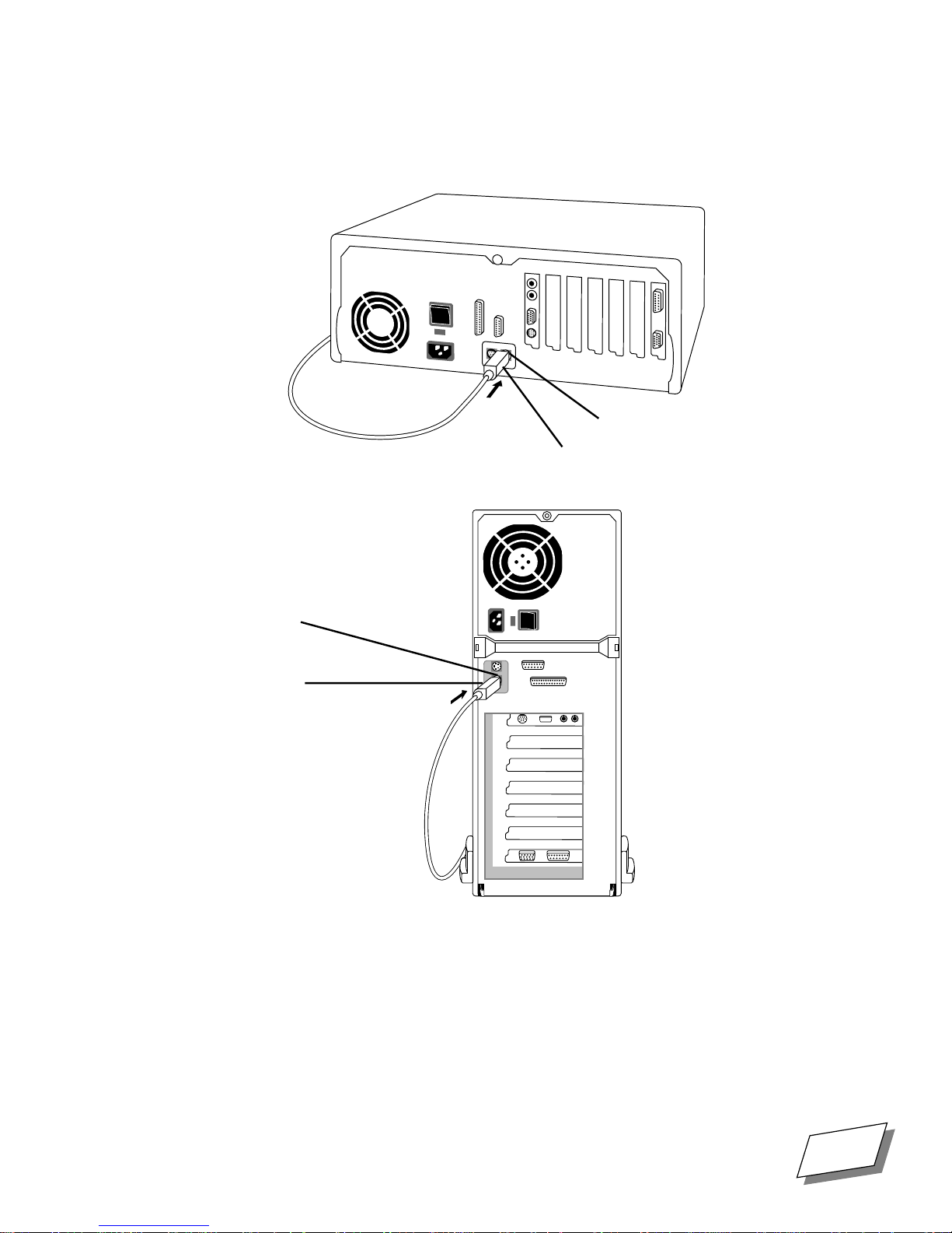
2.
Plug the keyboard cable into the ADB port (marked with V
the computer.
I
0
ADB port
Keyboard
cable
Getting Started
) on the back of
ADB port
Keyboard
cable
I
0
For Technical Support, Call 1-800-708-6227
Power 100/120 User Guide
7
Page 26

Getting Started
Turning the computer on
When the computer, monitor, keyboard, and mouse are connected, you can turn the computer on.
To turn the computer on:
1.
Turn on the monitor.
See the documentation that came with the monitor for the location of the power switch.
2.
Turn on the main power switch on the back of the computer.
The power is on when the side of the switch marked with is depressed. After the Þrst time you
turn on the computer, you normally will not need to use the power switch, because you will use the
keyboard, front-panel and on-screen Shut Down switches. Boy can you ever turn this sucker on and
off!
3.
Turn the computer on by pressing the Power key (marked with a triangle)
on the upper right corner of the keyboard or the Power On button on the
front of the computer.
When the computer Þnishes its start-up procedure, you should see the Mac OS desktop. If you see a
blinking question mark, you need to install the system software on your hard disk. See
Appendix C, ÒInstalling System Software,Ó on page 57
not already described, see the section following this one,
When you need to shut your computer down, follow the instructions in
Problems starting up
If you see a blank screen when you start up, check the following items to identify the source of the
problem:
■
Are the computer and monitor plugged in? If they are plugged into a power strip, is it turned on?
■
Are the computer and monitor turned on? The power light on the front of the computer should be
on. Most monitors also have power lights.
■
Is the video cable securely connected to the monitor and computer? (If you need to reattach the
cable, Þrst turn off the computer and monitor.)
■
Are the keyboard and mouse properly connected to the computer? (If you need to reconnect them,
Þrst turn off the computer to avoid damage.)
■
Is the brightness control on the monitor turned too far down? Check the documentation that came
with your monitor for instructions.
If you see a blank screen or anything
ÒProblems starting up.Ó
ÒShutting downÓ on page 11
.
8
Power 100/120 User Guide
For Technical Support, Call 1-800-708-6227
Page 27

Getting Started With
Mac OS
Chapter
2
Your computer uses the Mac OS operating system, which offers a unique combination of
power and ease of use. This chapter offers very basic instructions about how to use the builtin learning features of Mac OS. It also explains how to shut down your computer properly.
For more detailed information about the Mac OS, refer to
Dummies
Running the Basics tutorial
Mac OS includes a tutorial program called MacªOS Tutorial that shows you how to use the
fundamental features of the software. If you are brand new to Mac OS, we suggest you
complete the tutorial before you begin working with your computer.
In Mac OS, you use the mouse for tasks such as choosing menu commands or starting
programs. When you move the mouse, the
sometimes referred to as the
mouse pointer over an icon and clicking twice quickly (
folder or launch a program.
.
cursor
) moves in the same direction. By placing the tip of the
mouse pointer
Macintosh System 7.5 For
(the small arrow on the screen,
double-clicking
), you can open a
2
To run the Basics program:
1.
In the Mac OS desktop, double-click the icon that represents your hard disk
(located in the upper-right corner of the screen). Be careful to place the
mouse pointer over the icon, not on the words below.
The hard disk icon Òopens,Ó displaying a ÒwindowÓ containing the Þles and folders
stored on the hard disk.
2.
Double-click the folder called MacªOS Tutorial.
The folder opens, displaying the
3.
Double-click the MacªOS Tutorial Part 1 icon.
The program starts up, displaying an introductory screen.
4.
Follow the on-screen instructions to complete the tutorial.
For Technical Support, Call 1-800-708-6227
MacªOS Tutorial Par t 1
Power 100/120 User Guide
icon.
9
Page 28
Getting Started With Mac OS
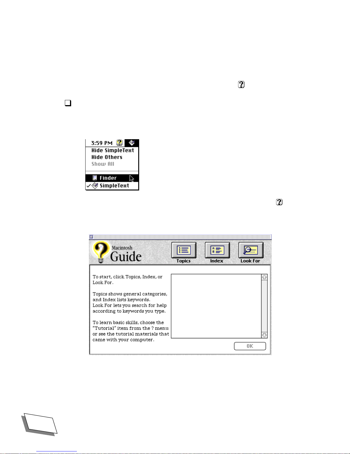
Using on-line help
Mac OS (and many applications that run under it) include an on-line help system with
information about using the software. The help system for Mac OS is called Macintosh
Guide and is available through the Guide menu (marked with ).
To use Macintosh Guide
1.
Choose Finder from the Application menu (in the upper-right corner of the
desktop) to make it the active application.
2.
Choose Macintosh Guide from the Guide menu (marked with ) or
xx
press xx
The Macintosh Guide window appears.
-?.
3.
Follow the on-screen instructions to get the information you need.
10
Power 100/120 User Guide
For Technical Support, Call 1-800-708-6227
Page 29

Shutting down
When you are Þnished working with your computer, it is very important to shut it down
correctly.
To shut down the computer:
1.
Choose Shut Down from the Special menu in Mac OS.
You are prompted to save any unsaved Þles before shutting down.
Getting Started With Mac OS
CAUTION:
open documents may be lost and you may damage your System folder.
Do not use the power switch to turn off the computer. If you do, unsaved or
For Technical Support, Call 1-800-708-6227
Power 100/120 User Guide
11
Page 30

Getting Started With Mac OS
12
Power 100/120 User Guide
For Technical Support, Call 1-800-708-6227
Page 31

Upgrading Your
Computer
Chapter
3
This chapter explains how to enhance the capabilities of your computer by adding expansion
cards, additional memory, and internal devices such as an additional hard disk. It also
explains how to switch between the Macintosh-standard and VGA high-performance ports.
You can add additional audiovisual capabilities by installing an optional video card. Contact
Technical Support at 1-800-708-6227 for information.
Removing the cover
Installing expansion cards and switching monitor ports requires that you remove the
computerÕs cover. The cover is designed for easy removal; no tools are required.
CAUTION!
1. If you are not proÞcient with electronic equipment, Power Computing
Corporation recommends that you have a certiÞed technician install RAM
and/or NuBus expansion cards. If you attempt to install RAM or cards
yourself, any damage you may cause to your equipment will not be
covered by the limited warranty on your computer. Please call technical
support at 1-800-708-6227 for additional information about this or any
other warranty question.
3
2. If an anti-static bracelet was supplied with the expansion card or other
device that you are installing, put it on and ground it as directed by your
instructions before touching any components inside the computer.
3. Never operate the computer with the cover removed.
For Technical Support, Call 1-800-708-6227
Power 100/120 User Guide
13
Page 32
Upgrading Your Computer
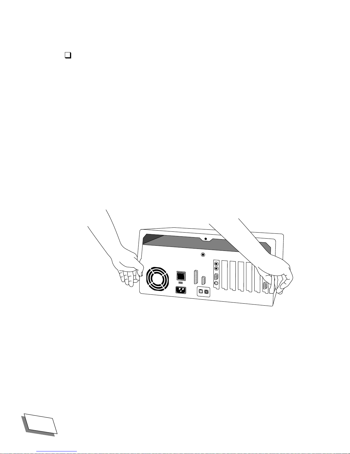
To remove the cover:
1.
Shut down the computer, turn off the monitor, and turn off the computer at
the main power switch on the back of the computer, but leave it plugged in.
Leaving the computer plugged in ensures that it is grounded.
2.
If the monitor is on top of the computer, disconnect it if necessary, and set
it aside.
Otherwise itÕs going to be awkward to remove the computer cover.
3.
Disconnect everything but the power cord from the back of the computer.
4.
Rotate the computer so that its back panel faces you.
5.
Remove the large thumb screw from the rear of the computer.
Put the thumb screw in your left front pocket or somewhere else where you wonÕt lose it.
6.
Pull apart the bottom corners of the cover, lift it off and set it aside.
Pull apart and lift off
I
0
14
Power 100/120 User Guide
For Technical Support, Call 1-800-708-6227
Page 33
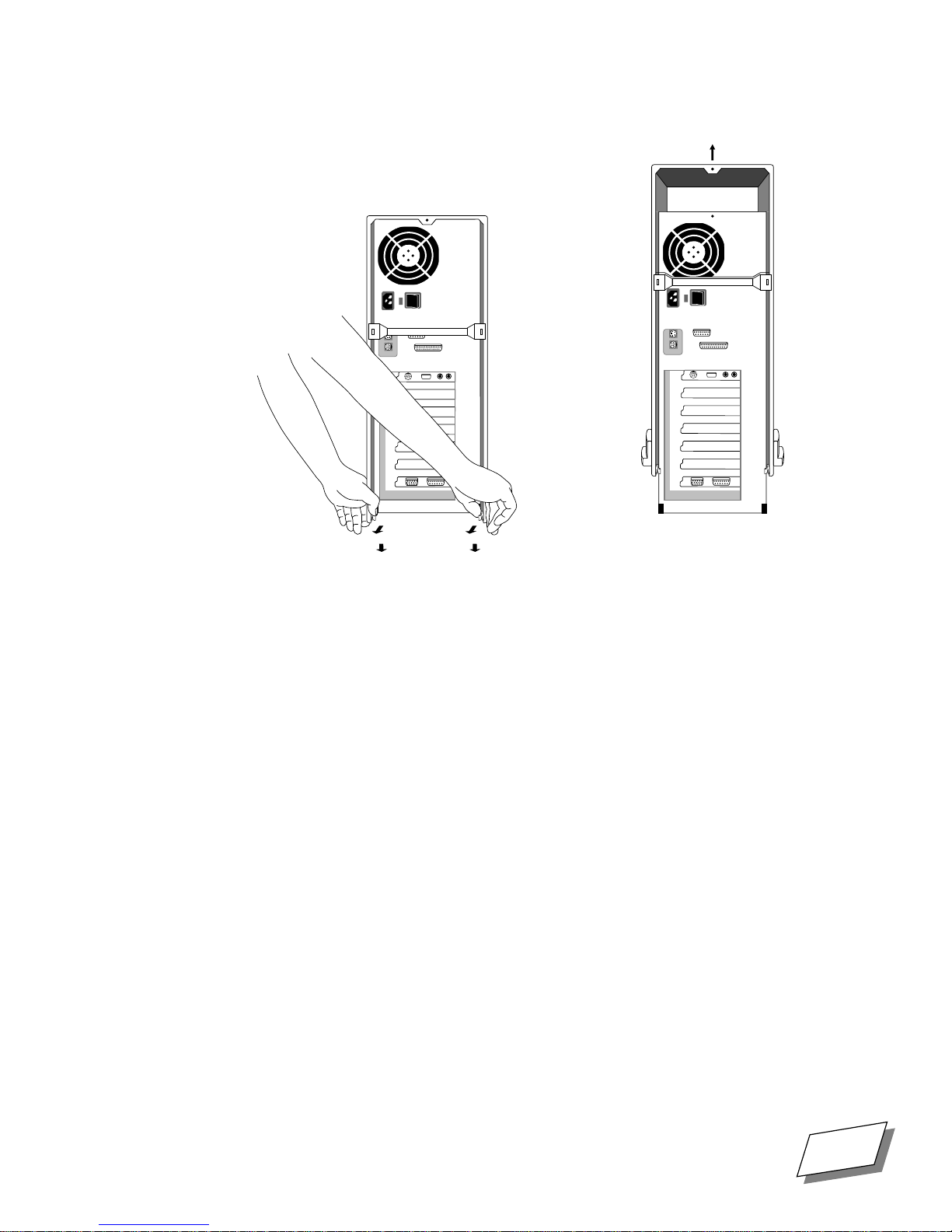
Upgrading Your Computer
Pull apart
I
0
7.
If you are working on a tower system, gently lay the computer on its side as
Lift off
I
0
shown in the next step.
For Technical Support, Call 1-800-708-6227
Power 100/120 User Guide
15
Page 34
Upgrading Your Computer
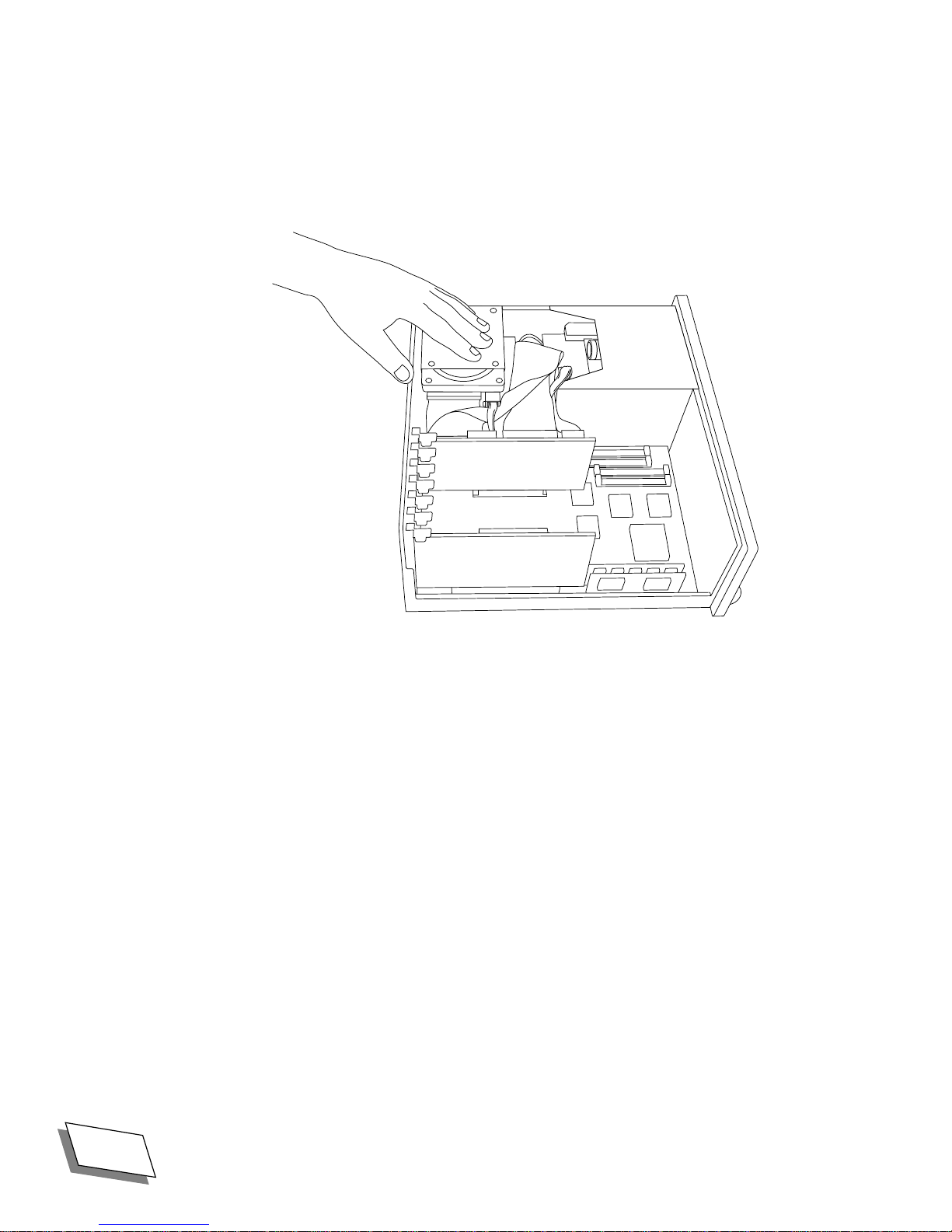
8.
Before touching any components or anything inside the computer, touch
the metal plate over the hard disk drive to discharge any static electricity
that might have built up on your clothes or body.
To replace the cover, reverse steps 5, 6,. and 7; then replace and re-connect everything.
16
Power 100/120 User Guide
For Technical Support, Call 1-800-708-6227
Page 35
Installing expansion cards
You can install expansion cards that enhance your computerÕs capabilitiesÑfor example, by
increasing processing power, improving graphics and video performance, or adding
networking and communications capabilities.
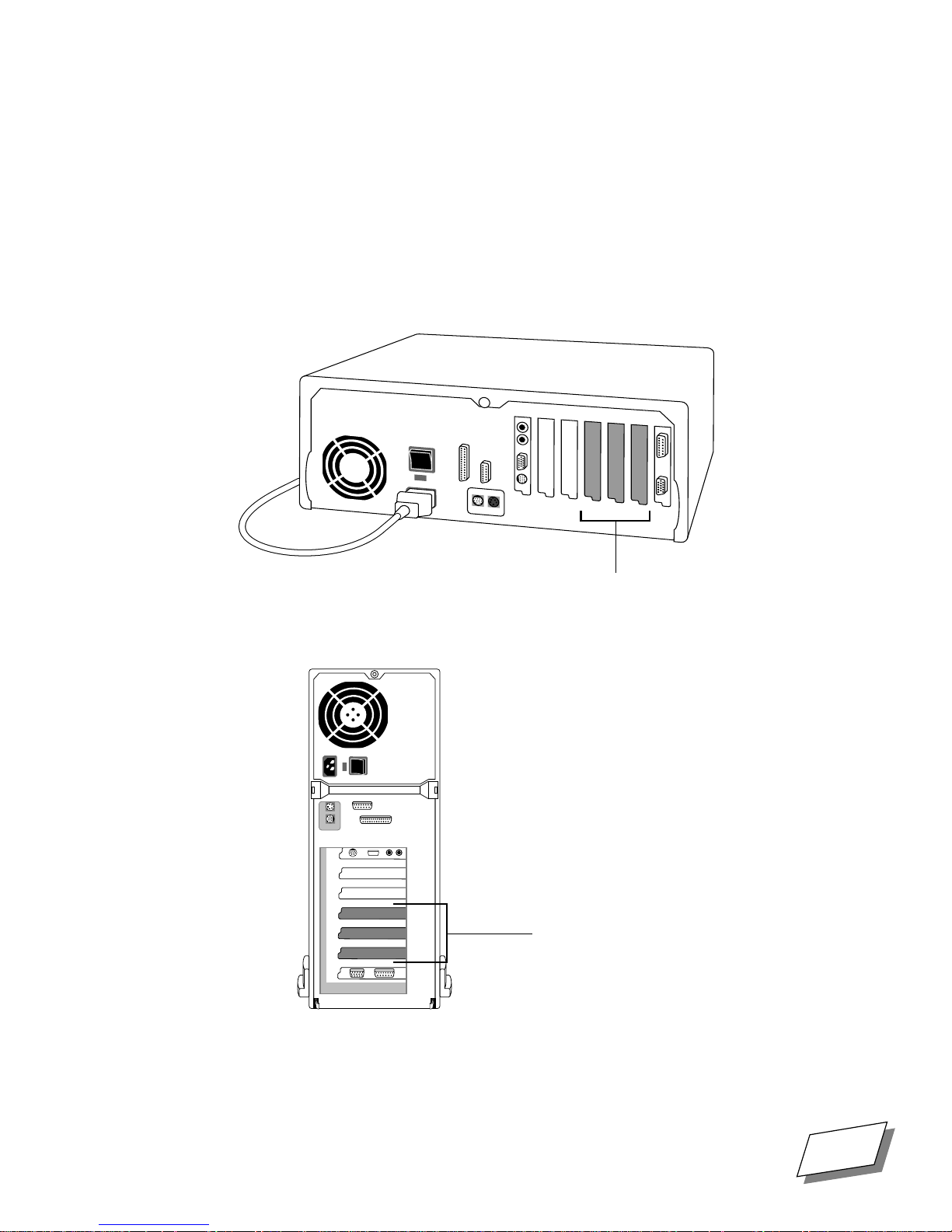
Your computer has three expansion slots designed to accept NuBus cards. NuBus cards
designed for use in the Apple Macintosh II family of computers are generally compatible.
I
0
Upgrading Your Computer
Back Detail Slots
0
NuBus expansion slots
I
NuBus expansion slots
Before you install any expansion cards, be sure to follow these guidelines to protect your
computer:
For Technical Support, Call 1-800-708-6227
Power 100/120 User Guide
17
Page 36

Upgrading Your Computer
■
Do not remove factory-installed cards from inside the computer. Removing a card
incorrectly can damage it and the computer. Contact Technical Support if you believe a
factory-installed card requires repair or replacement.
■
The combined power consumption of the expansion cards you install must not exceed the
limits of your computer. Refer to the documentation that came with your cards for their
power consumption and to ÒPower requirementsÓ on page 63 in this manual for the
power consumption limit for your computer.
■
Some cards may need to be installed by an authorized service provider. Refer to the
documentation that came with the card.
18
Power 100/120 User Guide
For Technical Support, Call 1-800-708-6227
Page 37
Upgrading Your Computer
To install an expansion card:
1.
Remove the computerÕs cover.
See ÒRemoving the cover,Ó starting on page 13 for instructions.
WARNING!
Turn off the main power switch before removing the cover and make sure
to touch the metal plate over the hard disk to discharge static electricity
before touching any components.
2.
Remove the metal cover from the slot you want to use.
To remove the cover, pull it up and away from the back panel.
3.
Remove the card from its static-proof bag.
Hold the card by its edges to avoid touching components.
4.
Align the card over the slot.
Make sure that the connector on the bottom aligns with the connector inside the slot and
that the hole in the cardÕs bracket aligns with the tab on the inside of the back panel.
5.
Push the card into the slot until it is Þrmly seated. The hole in the cardÕs
bracket should snap into place over the tab on the back panel.
Do not force the card. If you feel a lot of resistance, pull the card out, realign it, and
insert it again.
For Technical Support, Call 1-800-708-6227
NuBus card
Power 100/120 User Guide
19
Page 38
Upgrading Your Computer
6.
Replace the computer cover and tighten the screw.
WARNING!
To prevent electrical shock, always replace the cover before turning on the
computer.
Switching video ports
The computer comes equipped with a high-performance video card with two monitor
portsÑa Macintosh-standard port and a VGA port. The video card has a switch that selects
one of the ports.
When the computer comes from the factory, the
is the Þrst time the computer has been set up and you want to connect a monitor to the VGA
port, you will need to switch monitor ports as shown below. If you want to connect to the
VGA
port, or if you think the video port selection may have been changed, use the switch to
enable the port you want.
To switch monitor ports:
1.
Remove the computerÕs cover.
See ÒRemoving the cover,Ó starting on page 13 for instructions.
WARNING!
Turn off the main power switch before removing the cover and make sure
to touch the metal plate over the hard disk to discharge static electricity
before touching any components.
Macintosh standard
port is enabled. If this
20
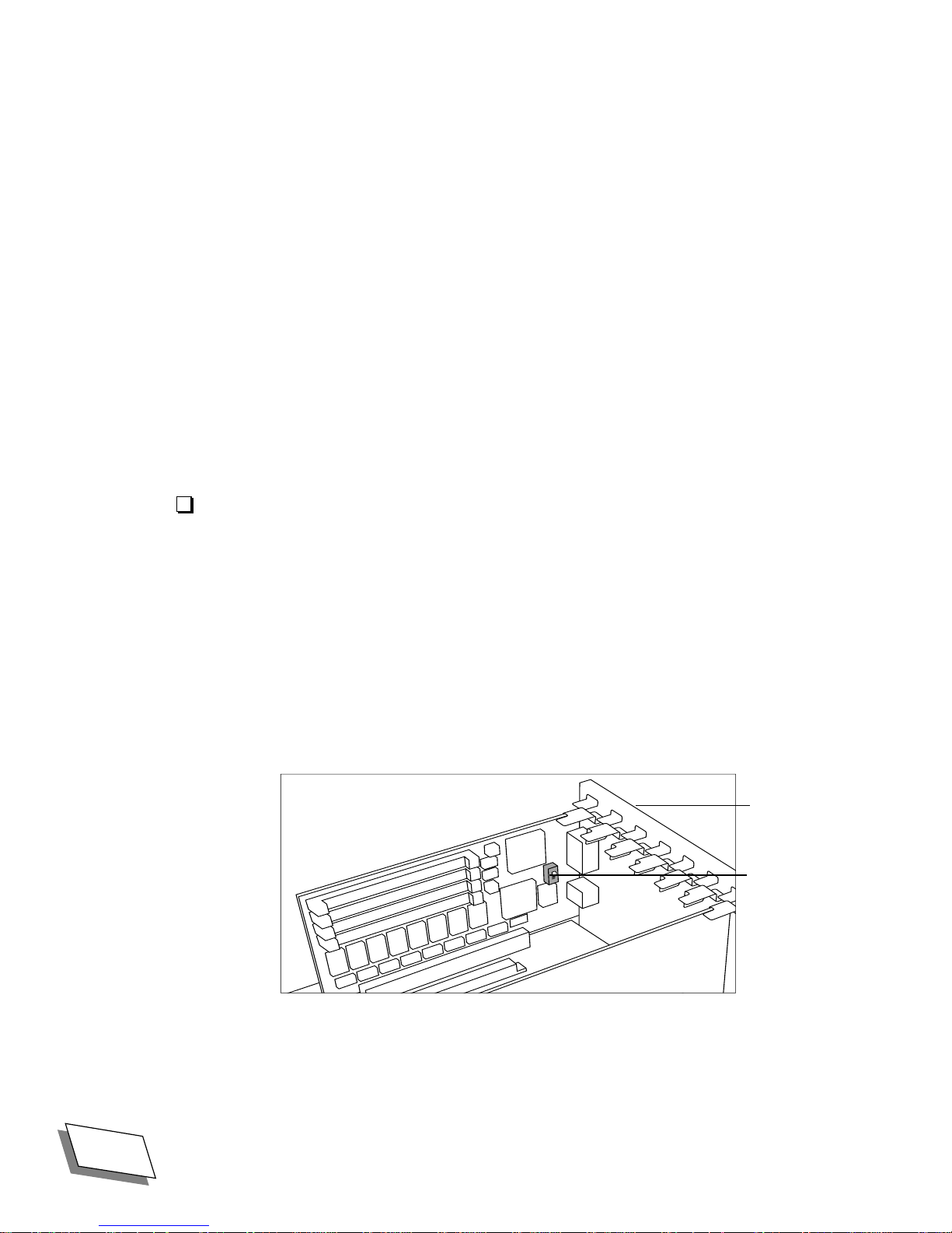
2.
Locate the switch on the video card.
Power 100/120 User Guide
Back panel
Video port
switch
For Technical Support, Call 1-800-708-6227
Page 39

3.
Flip the switch to the up position to enable the Macintosh-standard port.
Flip it down to enable the VGA port.
4.
Replace the computer cover and tighten the screw.
Increasing memory
Your computerÕs random-access memory (RAM) and video memory (VRAM) can be
increased. Memory is increased by installing or replacing memory modules (SIMMs, or
single in-line memory modules) in the computer. Make sure that the memory modules you
purchase are the right ones for your computer. See Appendix D, ÒTechnical Information,Ó on
page 59 for technical speciÞcations.
Upgrading Your Computer
For Technical Support, Call 1-800-708-6227
Power 100/120 User Guide
21
Page 40
Upgrading Your Computer
D
What you need to know about increasing RAM
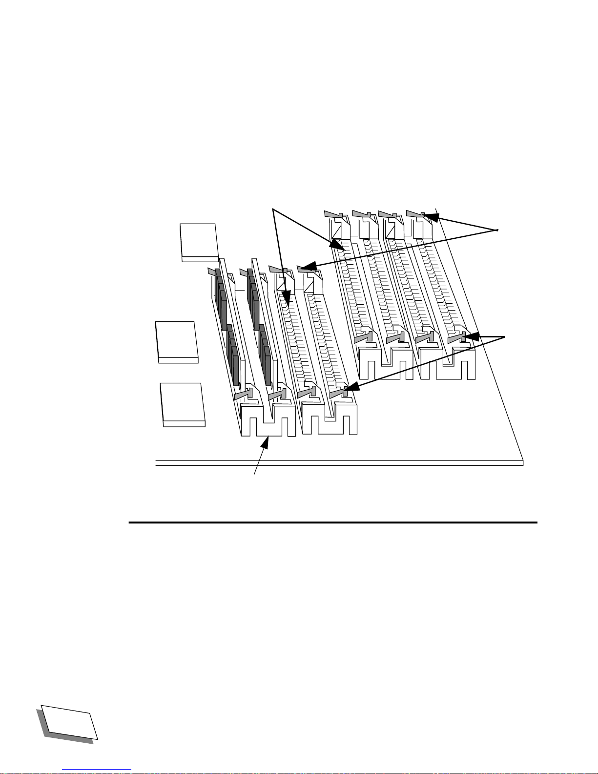
The computer has four pairs of SIMM clips (banks in engineerese) on the motherboard, near
the front, next to the ßoppy disk drive (see the illustration below). The SIMM clips are
organized into four pairs, the motherboard DRAM bank, bank A, bank B, and bank C.
slots
clips
ßoppy
drive
area
clips
bank C
donÕt
have to match.
bank B
bank A
motherboard DRAM
8 MB (two 4 MB SIMMs)
Do not remove.
The motherboard bank is the pair of clips farthest from the ßoppy drive cavity, A is next, etc.
The motherboard bank comes with two 4 megabyte SIMMs, which are required for the
system to work. Do not replace the SIMMs in the motherboard bank with SIMMs of any
other capacity; that bank will only work with two 4 megabyte chips.
Banks A, B, and C can be Þlled with 4, 8, 16, or 32 megabyte SIMMs, so you can install a
maximum of 200 megabytes of RAM (8 megabytes in the motherboard bank and 64 (32 per
slot) in each of the other banks, A-C).
SIMMs must be installed one pair per bank. Both slots in a bank must be Þlled with SIMMs
of the same capacity (4, 8, 16, or 32 megabyte), but different banks
front
22
Power 100/120 User Guide
For Technical Support, Call 1-800-708-6227
Page 41

Upgrading Your Computer
Banks A, B, and C can be Þlled in any order
easiest to start with the last clip in Bank C. Insert the rightmost SIMM of a pair Þrst.
If you are installing SIMMs in bank A, loosen the rightmost SIMM in the motherboard bank
to get the leftmost bank A SIMM in.
All SIMMs must be 72-pin, fast-paged mode, 80-nanosecond RAM access time or faster.
Slower SIMMs will not work reliably. 30-pin SIMMs from older Macintosh computers and
DIMMs (Dual In-line Memory Modules) from PCI Macintosh computers are not
compatible. Make sure that the memory modules you purchase are the right ones for your
computer.
To increase your systemÕs RAM. install additional SIMM modules in vacant DRAM banks;
if there are no vacant banks, replace installed SIMM modules with modules of higher
capacity.
Installing and Removing RAM
CAUTION!
1. If you are not proÞcient with electronic equipment, Power Computing
Corporation recommends that you have a certiÞed technician install RAM
and/or NuBus expansion cards. If you attempt to install RAM yourself, any
damage you may cause to your equipment will not be covered by the
limited warranty on your computer. Please call technical support at 1-800708-6227 for additional information about this or any other warranty
question.
as long as both slots in the bank are Þlled. It is
WARNING!
2. If an anti-static bracelet is available, put it on and ground it to your
computer before touching any components inside the computer.
3. Handle SIMM s by the ends and avoid touching their contacts or other
metal components.
4. Always store SIMMs in conductive bags.
5. Take your time; donÕt push yourself.
Prepare the computer
1.
If you havenÕt done so, remove the cover from the computer.
See ÒRemoving the cover,Ó starting on page 13 for instructions.
Turn off the main power switch before removing the cover.
For Technical Support, Call 1-800-708-6227
Power 100/120 User Guide
23
Page 42

Upgrading Your Computer
2.
Touch the metal plate over the hard disk drive to discharge any static
electricity that might have built up on your clothes or body.
I/O Board
floppy
drive
floppy drive
connector
SIMM banks
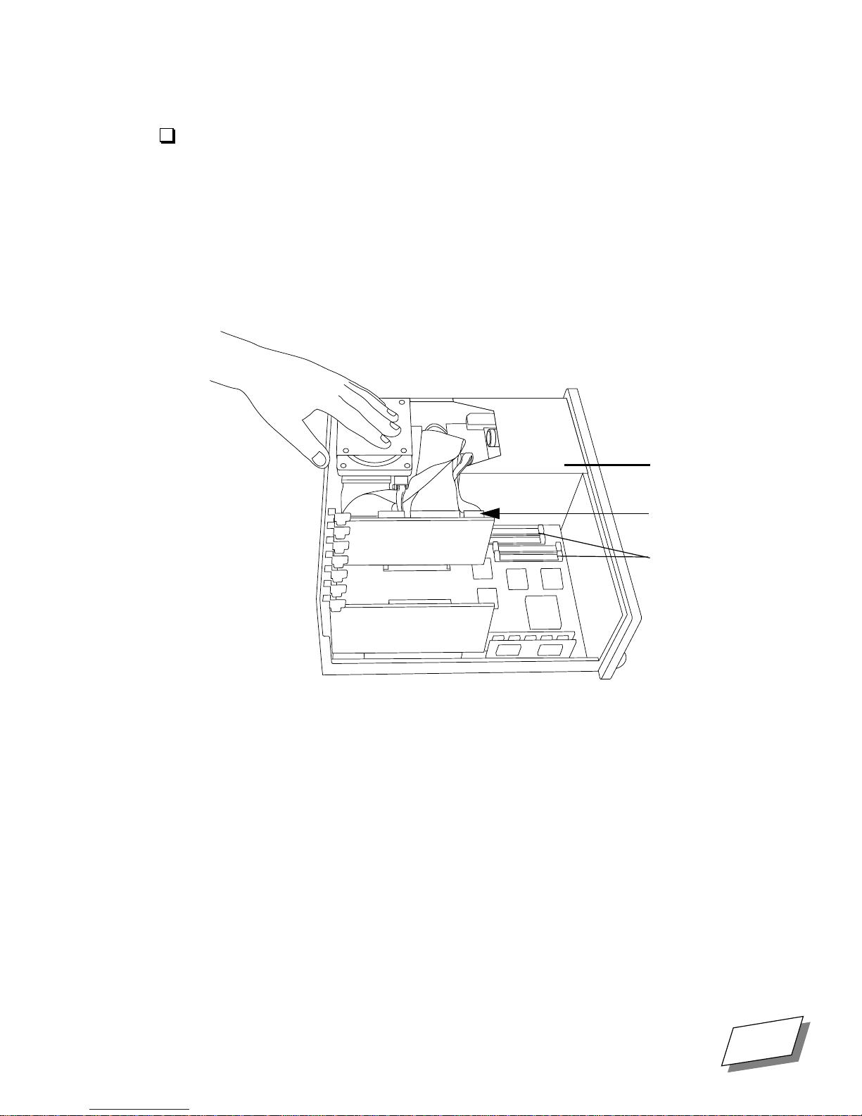
3.
Disconnect the ßoppy disk drive connector, the CD audio connector, if you
have one, (below the ßoppy connector), and the speaker connector (below
the CD audio connector) from the I/O board and move those cords out of
the way.
If you are installing in bank A and you have small supple Þngers you may be able to
install SIMMs without disconnecting these cables, but this makes it easier.
24
Power 100/120 User Guide
For Technical Support, Call 1-800-708-6227
Page 43

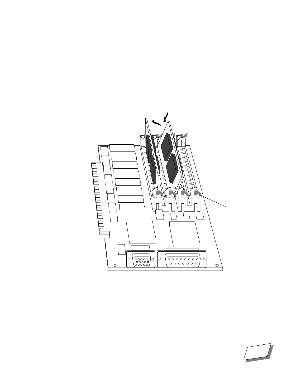
Removing a SIMM.
R
Upgrading Your Computer
SIMM clip
SIMM
Module
D
SIMM clip
front
1.
If you need to remove a SIMM module to make room for a higher-capacity
one, reach in and push down and out on the tiny handles which stick up
from the small metal SIMM clips at each end of the SIMM slot.
2.
The SIMM clips should click loose and module should tilt to the left so that
you can then slide the module out of the slot at about a 60 degree angle.
3.
If the SIMM module does not come free, press the SIMM clips down again
and try to push the top of the module gently away from the drives.
4.
When you are Þnished with SIMM removal and insertion, re-connect the
ßoppy disk drive connector, the CD audio connector (below the ßoppy
connector), and the speaker connector (below the CD audio connector)
from the I/O board and move those cords out of the way and replace the
cover.
For Technical Support, Call 1-800-708-6227
Power 100/120 User Guide
25
Page 44
Upgrading Your Computer
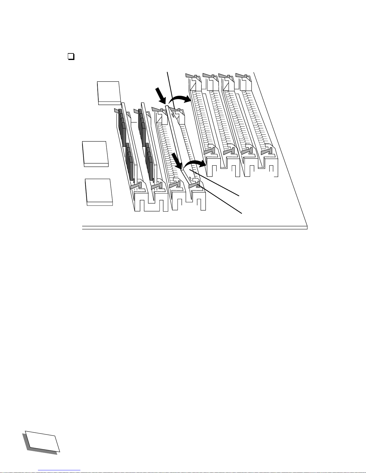
Inserting a SIMM
SIMM clip
ßoppy
drive
area
bank B
bank C
SIMM Module
bank A
front
1.
To insert a SIMM module, hold the module by the ends with the contacts
down and the slotted end toward the back of the computer.
Banks A, B, and C can be Þlled in any order
SIMMs of the same capacity. It is easiest to start with the last clip in Bank C. Insert the
rightmost SIMM of a pair Þrst.
If you are installing SIMMs in bank A, loosen the rightmost SIMM in the motherboard bank
to get the leftmost bank A SIMM in.
2.
Slide the contacts into the slot at about a 60 degree angle and make sure
the contacts are Þrmly seated in the slot,
3.
Gently pull the top of the module toward the ßoppy drive side of the
computer until you hear the metal clips click into place.
as long as both slots in the bank are Þlled with
SIMM clip
4.
If both clips do not click into place, release any clip that did click, pull the
SIMM module out, re-seat it in the slot, and try again.
5.
When you are Þnished, re-connect the ßoppy disk drive connector, the CD
audio connector (below the ßoppy connector), and the speaker connector
(below the CD audio connector) from the I/O board and move those cords
out of the way and replace the cover.
26
Power 100/120 User Guide
For Technical Support, Call 1-800-708-6227
Page 45
Increasing VRAM
The video memory available to monitors connected to the high-performance monitor ports is
increased by installing video memory modules. Your computer is equipped by default with 2
MB of VRAM, which can be expanded to 4 MB by using 512K VRAM SIMMs.
The location of the VRAM slots on the high-performance video card is shown below. To
install a video memory module, insert it an angle into the slot, then tilt it up until the small
metal clips are engaged, just as DRAM is inserted, as described in ÒInserting a SIMMÓ on
page 26.
Upgrading Your Computer
Metal clip
The amount of VRAM determines the number of colors that can be displayed on monitors of
different sizes. See ÒVRAM conÞgurationsÓ on page 62 for tables listing the number of
colors that can be displayed on various-sized monitors with different amounts of VRAM.
For Technical Support, Call 1-800-708-6227
Power 100/120 User Guide
27
Page 46
Upgrading Your Computer
Installing internal drives
What you need to know about installing internal drives
In addition to the ßoppy disk drive and the built-in hard disk, the desktop computer has space
for two 5.25-inch internal drives, such as additional hard drives, CD-ROM drives, or other
removable-media drives. The tower has room for three. Standard 5.25 drives. With an adapter
tray, 3.5 inch devices can be installed in these storage bays.
If your computer came with an internal 35
CD-ROM drive, it is already installed in one of these bays.
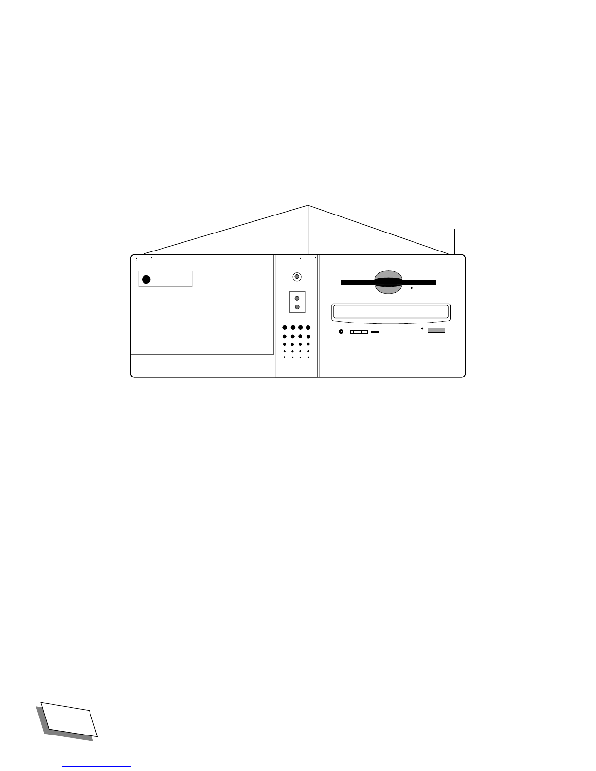
The location of the 5.25 inch bays is shown below. For clarity, the illustration shows the
computer with its front panel (bezel in engineerese) removed
.
Floppy
disk
drive
5.25 inch
internal
storage
bays
28 Power 100/120 User Guide For Technical Support, Call 1-800-708-6227
Page 47

Upgrading Your Computer
5.25 inch internal
storage bays
Floppy
disk
drive
Rails for mounting internal devices are available from Power Computing for a nominal fee;
contact our Sales Department at 1-800-999-7279. Rails, as well as adapter trays for installing
3.5 inch drives in the 5.25 inch bays are also available at most computer parts stores.
The Power 100/120 uses an internal SCSI (Small Computer Systems Interface) bus to
connect internal drives. For a more detailed discussion of how the SCSI bus on your
computer is set up, see ÒUsing SCSI devices,Ó starting on page 41. Pay particular attention to
the discussion of SCSI termination, discussed in ÒEnsuring proper terminationÓ on page 34.
Required tools
Small Philip-head screwdriver
Drive rails, if not supplied with the drive
3.5 inch to 5.25 inch drive adapter tray, if you are installing a 3.5 inch drive.
Software drivers, if required
For Technical Support, Call 1-800-708-6227 Power 100/120 User Guide 29
Page 48

Upgrading Your Computer
Installing drives
CAUTION! 1. If you are not proÞcient with electronic equipment, Power Computing
Corporation recommends that you have a certiÞed technician install
internal drives. If you attempt to install an internal drive yourself, any
damage you may cause to your equipment will not be covered by the
limited warranty on your computer. Please call technical support at 1-800708-6227 for additional information about this or any other warranty
question.
2. If an anti-static bracelet is available, put it on and ground it to your
computer before touching any components inside the computer.
3. Handle drives carefully and avoid touching their contacts or moving
parts.
4. Always store drives in conductive bags.
5. Take your time; donÕt push yourself.
Prepare the drive
1. Install software drivers
Some SCSI devices require special software called device drivers to operate with your
computer. If a device driver is required, it is normally supplied with the device; if you are
unsure whether one is required, contact the manufacturer of the device. Follow the driver
installation instructions supplied by the manufacturer. If a device driver is not supplied,
you can generally assume that the device does not need one. The drives pre-installed in
your system have pre-installed drivers.
30 Power 100/120 User Guide For Technical Support, Call 1-800-708-6227
Page 49
Upgrading Your Computer
2.
Set SCSI ID
Following the instructions which came with your device, set its SCSI ID. Replacement
drives provided by Power will normally come with SCSI ID pre-set to 0 for the primary
hard drive and 3 for a CD-ROM.
Each device in a SCSI chain requires a unique number called a SCSI ID, which the
computer uses to identify the device. In the internal bus, the computer itself is assigned
SCSI ID 7 and the primary internal hard disk is assigned SCSI ID 0. Every other device
you install must have a unique number from 1 to 6. (The internal CD-ROM drive, if
installed, is assigned SCSI ID 3.)
To determine what SCSI IDs have already been assigned to which devices, go to the
Hard Disk Toolkitª PE folder in the Utilities folder on your hard disk and run HDT
Primerª PE. HDT Primer will scan your SCSI bus and display the SCSI ID, name, and
other parameters of all of the SCSI devices on the bus (see example below).
I
0
Back Detail Slots
Since your computer has two SCSI buses, one internal and the other external, make sure
to scan the internal one by selecting Bus 0: Apple [Internal] under HDT PrimerÕs
SCSI Bus menu. For details on HDT Primer, see ÒLaunching HDT Primer PE,Ó starting
on page 92.
3. Install a 3.5 inch drive in a 3.5 to 5.25 inch adapter tray
Since the internal drive bays are designed to accommodate 5.25 inch drives, if you are
installing a 3.5 inch drive, you will need to mount it in a 3.5 to 5.25 inch adapter tray. 3.5
to 5.25 inch adapter trays are available at most computer parts stores.
For Technical Support, Call 1-800-708-6227 Power 100/120 User Guide 31
Page 50

Upgrading Your Computer
4. Install rails
Drives are held in place in the computer chassis by plastic rails mounted on each side,
which Þt into a mounting track in the chassis. Some drives come with rails already
installed. See illustration below.
drive (3.5Ó shown)
rail
optional 3.5Ó to 5.25Ó
adapter tray
front
rail
ßexible tab end of rail
If you got your drive from Power Computing, the tracks should be included and are
probably already attached. If for some reason your Power Computing drive came without
rails, call Power Computing Customer Support at 1-800-671-6227.
If rails did not came with your drive, they are available from Power Computing for a
nominal fee through our Sales Department at
1-800-999-7279. Rails, as well as adapter trays for installing 3.5 inch drives in the 5.25
inch bays are also available at most computer parts stores.
If rails are not attached to the sides of your drive or adapter tray, attach one rail to each
side of the drive (or the adapter tray if you are installing a 3.5 inch drive) using the
screws supplied with the rails. Rails should be attached with the ßexible tabs toward the
front of the drive and the tracks facing out. See the illustration above.
32 Power 100/120 User Guide For Technical Support, Call 1-800-708-6227
Page 51
Upgrading Your Computer
Prepare the computer
1. If you havenÕt done so, remove the cover from the computer.
See ÒRemoving the cover,Ó starting on page 13 for instructions.
WARNING!
Turn off the main power switch before removing the cover.
2. Touch the metal plate over the hard disk drive to discharge any static
electricity that might have built up on your clothes or body.
floppy
drive
floppy drive
I/O Board
connector
SIMM banks
3. Disconnect the speaker connector, which is on the I/O board below the
ßoppy disk drive connector.
For Technical Support, Call 1-800-708-6227 Power 100/120 User Guide 33
Page 52
Upgrading Your Computer
4. Starting with the primary bezel tab, push down on the three tabs which
hold the bezel in place (see illustrations below) and pull the long tabbed
side of the bezel away from the case until the tabs on the other side of the
bezel clear the front of the computer. See illustrations below for the tab
locations on the desktop system and the tower system.
bezel tabs (on back)
primary
tab
34 Power 100/120 User Guide For Technical Support, Call 1-800-708-6227
Page 53

Upgrading Your Computer
bezel tabs
(on back)
primary
tab
5.
Pull the speaker cord out through the hole in the front of the computer and
set the bezel down away from the computer.
This step may not be necessary if your speaker cord is long and you have room for the
bezel near the computer.
For Technical Support, Call 1-800-708-6227 Power 100/120 User Guide 35
Page 54

Upgrading Your Computer
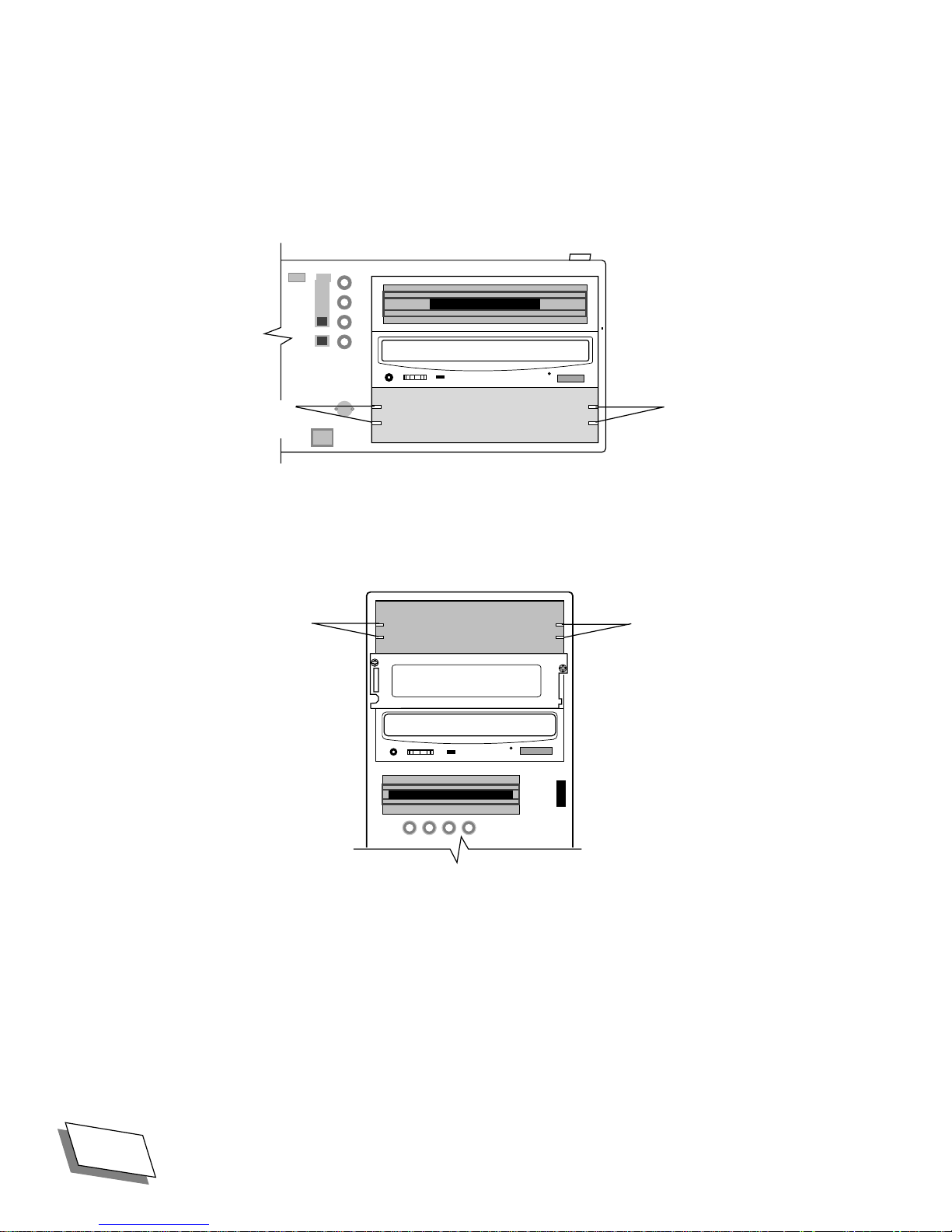
6. If you are installing a CD-ROM drive or other drive with removable media,
remove the plastic insert covering the bay you are planning to use from the
bezel. To remove the insert, press down on the plastic tab at one end of the
insert and pivot the insert out (see illustrations below).
tab
tab
plastic insert
Desktop Bezel, rear view
plastic insert
Tower Bezel, rear view
tab
tab
36 Power 100/120 User Guide For Technical Support, Call 1-800-708-6227
Page 55
Upgrading Your Computer
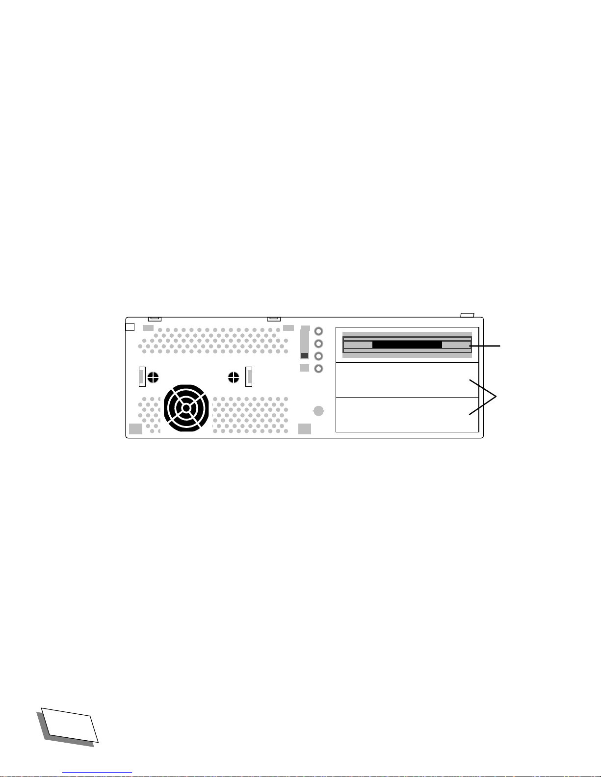
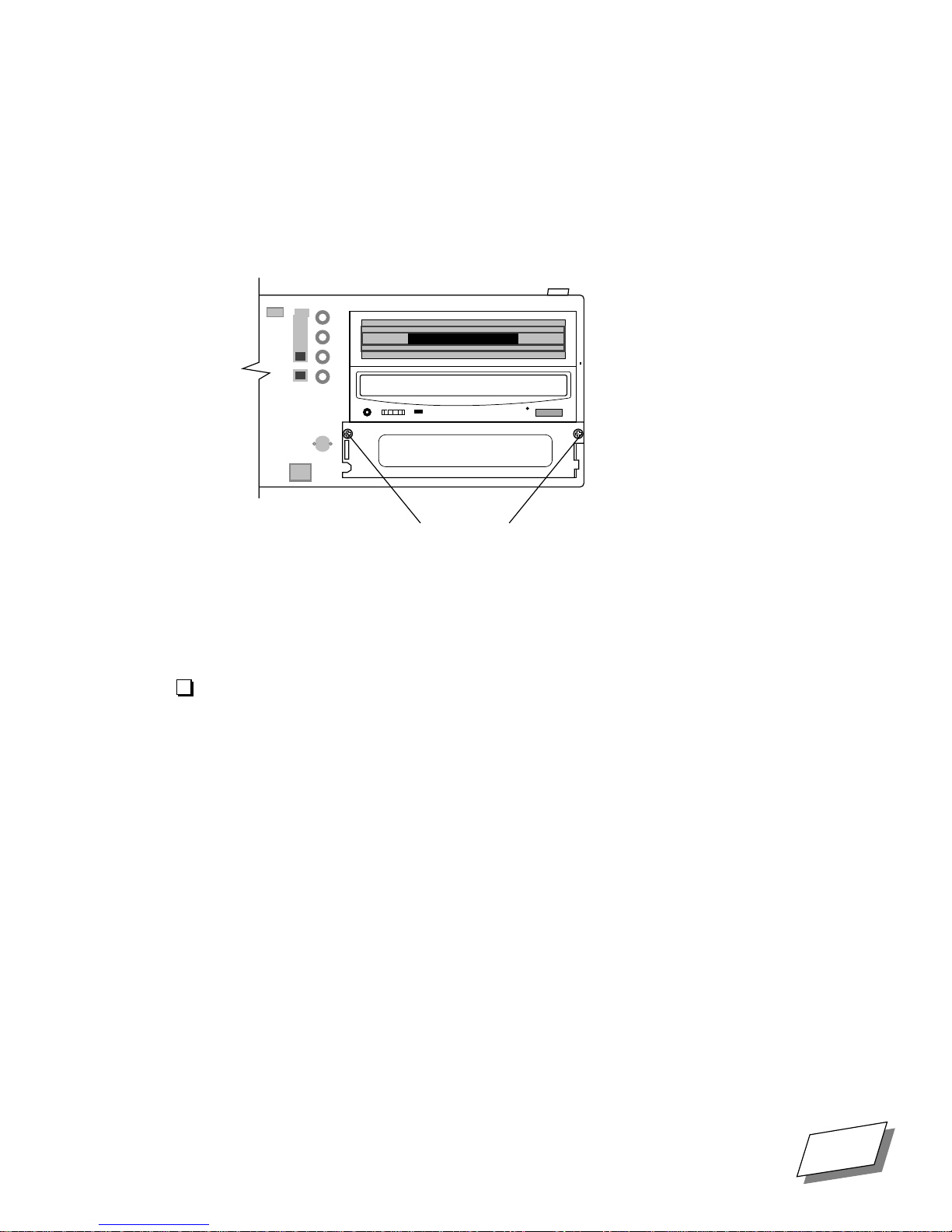
7.
Unscrew the two screws holding the metal bay cover, if there is one, in
front of the drive bay and set the plate and screws aside.
If you are installing a drive that does not use removable media, you will need to replace
this plate after you have installed the drive.
metal bay cover
screws
Note:
The slot under the ßoppy drive on the desktop model and the top slot on the
tower drive may have a metal plate without screws, which is attached by two thin
strips of metal. To remove that type of plate, simply bend it back and forth several
times until it comes loose, and remove it.
Install the drive
Once you have prepared the drive (see ÒPrepare the drive,Ó starting on page 30) and the
computer (see ÒPrepare the computer,Ó starting on page 33), you are ready to install the
drive.
Note:
mate them. If a cable is very hard to connect, examine it carefully to make sure you
have it oriented so that it Þts the connector it goes onto. Once cables are connected,
make sure they are snug.
Connectors are keyed, which means that there is only one correct way to
For Technical Support, Call 1-800-708-6227 Power 100/120 User Guide 37
Page 56
Upgrading Your Computer
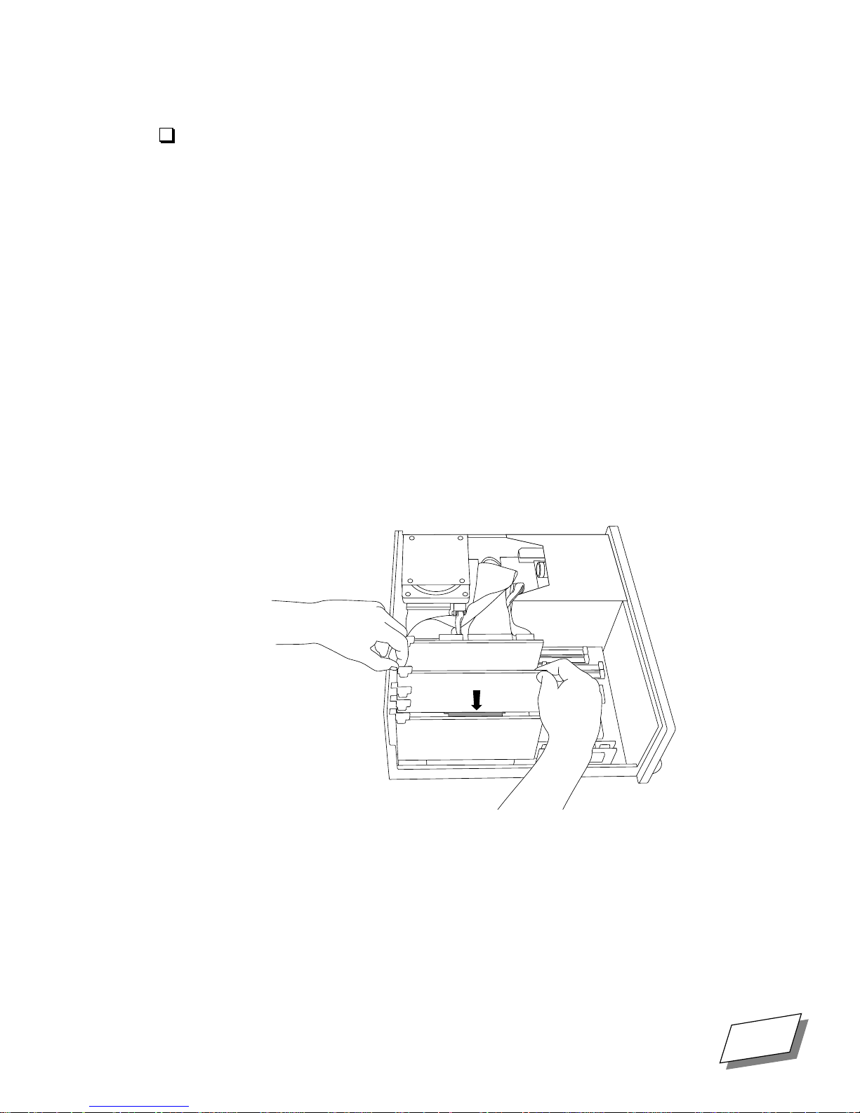
1. Slide the drive into the bay (see illustrations below), being careful not to
crimp or fold any cables. The drive rails slide into the tracks on the side of
the bay and the rails snap into place when the drive is all the way in.
tracks
for rails
tracks
for rails
tracks
for rails
Desktop Drive Bay
tracks
for rails
38 Power 100/120 User Guide For Technical Support, Call 1-800-708-6227
Tower Drive Bay
Page 57

Upgrading Your Computer
2.
Connect one of the unused connectors on the SCSI cable to the wide
connector on the drive (see illustration below).
Note:
There is a key in the middle of the top of the SCSI connector and a notch in
the cable connector which matches the key, to ensure that the cable is not plugged in
upside down. If the cable resists being plugged in, check to make sure the key and
slot are mating correctly.
Find the SCSI data cable inside the computer (it is the wide ßat ribbon cable connected
to the hard drive and, if you have one, the CD-ROM drive. The SCSI cable should have
one or two unused connectors on it. You may have to detach and re-attach the SCSI
connectors on one or more other drives to get connectors where you need them.
Remember, this is SCSI, so the ends have to be terminated. See ÒEnsuring proper
terminationÓ on page 34 for details.
connector
key
SCSI
connector
beveled socket
corners
power
connector
Rear View of Drive
3. Find an unused four-pin power cable in the set of cables coming from the
power supply (the power supply is in the right rear of the computer, on the
bottom) and connect that cable to the rear of the drive, being careful to
match the beveled corners of the plug to those of the socket (see
illustration above).
Check the instructions that came with the drive for jumper or switch settings and check
to make sure that they are properly set before going to the next step. Make sure the
connectors are snug.
4. If the drive does not use removable media, replace the metal cover plate in
front of the drive.
5. Lift the bezel up to the front of the computer, thread the speaker cord back
through the hole in the front panel, re-connect the speaker cord to the I/O
board, and replace the bezel.
6. Replace the cover, reconnect system components, turn main power back
on, and restart the computer.
For Technical Support, Call 1-800-708-6227 Power 100/120 User Guide 39
Page 58

Upgrading Your Computer
If the drive does not work,
1. Make sure that any required drivers are properly installed. See the driveÕs
documentation for more information.
2. Turn the system off, unplug the system components, and remove the
cover.
3. Make sure that the driveÕs data cable SCSI connector is plugged in and
seated Þrmly.
If the connection seems loose or crooked, check to make sure that no pins are bent and
that the connection is keyed properly. Bent pins may be carefully straightened with a
very small screwdriver.
4. Make sure that the driveÕs power cable is plugged in and seated Þrmly.
5. Make sure that each device in the internal SCSI chain has its own unique
SCSI ID: the primary hard drive should be set to ID
normally set to
0 and the CD_ROM is
3. (See ÒSet SCSI IDÓ on page 31.)
6. Make sure there are no internally-terminated devices in the SCSI chain. The
only internally-terminated device on the internal SCSI chain should be the
pre-installed primary internal hard drive.
7. Replace the computerÕs cover, re-connect system components, turn main
power back on, and restart the computer.
If these steps do not correct the problem, contact the drive manufacturer or Power
Computing Technical Support at 1-800-708-6227 for assistance.
40 Power 100/120 User Guide For Technical Support, Call 1-800-708-6227
Page 59

Connecting Peripheral
Devices
Chapter
4
Your computer has a number of ports for connecting peripheral devices such as printers,
storage devices, audio equipment, network cabling, and modems.
See ÒPower 100/120 OverviewÓ at the beginning of this manual for the location of the ports.
Using SCSI devices
Your computer has two separate SCSI busesÑone for the internal devices like the hard disk
and the optional CD-ROM drive and another for external devices. You can connect up to
seven devices in a
Connecting a SCSI device involves four steps:
■
Installing a software device driver (if one is required)
■
Setting the deviceÕs SCSI ID number
SCSI chain
4
to each bus.
■
Ensuring proper termination
■
Connecting the device
Installing software device drivers
Some SCSI devices require special software called device drivers to operate with your
computer. If a device driver is required, it is normally supplied with the device; if you are
unsure whether one is required, contact the manufacturer of the device. Follow the
installation instructions supplied by the manufacturer. If a device driver is not supplied, you
can assume that the device does not need one.
Setting the SCSI ID
Each device in a SCSI chain requires a unique number called a SCSI ID, which the computer
uses to identify the device. In the internal bus, the computer itself is assigned SCSI ID 7 and
the internal hard disk is assigned SCSI ID 0. Every other device you install must have a
unique number from 1 to 6. (The internal CD-ROM drive, if installed, is assigned SCSI ID
3.)
In the external bus, each device must be assigned a unique SCSI ID from 0 to 7.
For Technical Support, Call 1-800-708-6227
Power 100/120 User Guide
41
Page 60

Connecting Peripheral Devices
The way you assign SCSI IDs varies from device to device. On most external devices, the ID
is displayed on the back of the device. You usually change it by pressing small buttons above
or below the number display. For some external and most internal devices, changing the ID
requires setting switches or moving jumpers. Refer to the documentation that came with the
device for exact instructions.
The important thing to remember is that each device must have an ID that is unique within its
bus. If there is an ID conßict, your computer and the SCSI devices connected to it will
malfunction.
Ensuring proper termination
For a SCSI chain to work properly, it must be terminated correctly. The basic rule about
SCSI termination is simple: the device at the end of the chain must be
located between the computer and the end of the chain must be unterminated.
On the internal SCSI bus, any devices you install should be unterminated because the
computerÕs hard disk at the end of the bus is terminated and all of the internal connectors are
in the middle of the chain.
On the external bus, you need to consider where the device is placed in the chain and
whether it has an internal terminator. (Most SCSI devices use removable external
terminators, but some older devices have built-in terminators that are difÞcult to remove.)
terminated
. Devices
■
If you have an internally terminated device, place it at the end of the chain and remove
external terminators from other devices in the chain.
■
If none of the devices is internally terminated, place an external terminator on the last
device in the chain and on no other device.
See the documentation that came with each device for information about how it is
terminated.
Connecting an external SCSI device
The external SCSI port, marked with g
computer and devices such as hard disks, CD-ROM drives, scanners, printers, tape backup
drives, and so on.
To connect a single SCSI device (or the Þrst device in a chain), you need a SCSI cable with a
25-pin connector on one end and a 50-pin connector on the other. For each additional cable,
you need a cable with 50-pin connectors on both ends. The cables you use should be doubleshielded and have approximately 110-ohm impedance. Most SCSI problems are the result of
low-grade cables.
Note:
Devices on the SCSI bus which are turned off can cause system errors.
External SCSI devices which are connected to the computer must be turned on.
, provides high-speed communication between the
42
Power 100/120 User Guide
For Technical Support, Call 1-800-708-6227
Page 61

To connect an external SCSI device:
1.
Turn off the computer and the SCSI device.
2.
Make sure that the device has a unique SCSI ID from 1 to 6.
3.
Connect the device to the computerÕs SCSI port or to the last device in the
chain using the appropriate cable.
4.
Make sure that the last device in the chain is terminated.
Some devices require an external terminator, while others are internally terminated.
When you are ready to start up, turn on your SCSI devices before you turn on the computer.
If you do not, your computer will not recognize the devices.
Connecting an internal SCSI device
You install internal SCSI devices in one of the computerÕs internal storage bays. See
ÒInstalling internal storage devicesÓ in Chapter 3 for an illustration of the location of these
bays. Contact Technical Support for more information about installing internal SCSI devices.
Connecting Peripheral Devices
Connecting a printer
Your computer has a port (marked with [
connections or for LocalTalk network printer connections.
You can also connect a printer to the modem port (marked with
program to tell the Mac OS which port you are using. See Macintosh Guide for information
about the Chooser.
To connect the printer, follow the instructions that came with it.
Connecting input devices
Use the computerÕs ADB port (marked with V
trackball, graphics tablet, or bar-code reader. Depending on their power consumption, you
can connect up to three input devices in a chain from the ADB port.
The total power used by all the ADB devices must not exceed 500 milliamperes (mA). Check
the documentation that came with your ADB devices for information about their power
consumption.
). This port can be used for direct printer
W
). Use the Chooser
) to connect input devices such as a mouse,
For Technical Support, Call 1-800-708-6227
Power 100/120 User Guide
43
Page 62

Connecting Peripheral Devices
Connecting a modem or telecom adapter
Your computer is equipped with an enhanced telecommunications port (marked with W
which can be used with a standard modem or the Apple GeoPort Telecom Adapter. The
GeoPort Telecom Adapter offers advanced communications features not available with
standard modems. It is available from authorized Apple dealers.
To connect a modem or GeoPort Adapter, follow the instructions that came with it.
Connecting to a network
Your computer has built-in support for two different networking systemsÑLocalTalk and
Ethernet. Other networking systems are possible, but they require expansion cards.
Use the Network control panel in Mac OS to choose a networking system. See Macintosh
Guide for information about using your computer on a network.
Connecting to a LocalTalk network
Use the computerÕs printer port (marked with [
LocalTalk connectors and cables are available from several vendors. Follow the instructions
that came with the connector and cabling.
Connecting to an Ethernet network
),
) to connect to a LocalTalk network.
The computer has a built-in port (marked with G
networks. Using the appropriate adapter, you can connect to standard Ethernet wiring such as
10Base-T, thick coax, and thin coax. Adapters are available from several vendors. Follow the
manufacturerÕs instructions for connecting the adapter.
Connecting to a Token Ring network
You can connect to a Token Ring network by installing an expansion card and appropriate
networking software. Token Ring cards and software are available from several vendors.
Using audio equipment
Using the sound in and sound out ports of your computer, you can record and play highquality stereo audio. You can connect audio devices such as microphones, stereo equipment,
and speakers. (You can also use an external or internal CD-ROM drive to play audio CDs.
See ÒPlaying audio CDs on a CD-ROM driveÓ on page 47 later in this section.)
Understanding the sound ports
Your computer has two sound portsÑa sound output port (marked with -
X
input port (marked with
). Use these ports to connect audio devices.
) for connecting to high-speed Ethernet
) and a sound
44
Power 100/120 User Guide
For Technical Support, Call 1-800-708-6227
Page 63

Connecting Peripheral Devices
The sound ports accept a connector called a
used to connect headphones to a personal stereo. If an audio device has a different kind of
connector, you can buy an adapter at an electronics store.
Connecting an audio device
To play or record sounds, connect an audio device to your computer.
■
If you want to use your computer to work with the sound produced by a device like a
microphone, CD, or tape player, attach it to the sound input port.
■
If you want to use a device such as a tape recorder or external speakers to work with
sound produced by the computer, attach it to the sound output port.
A device that can both record and play (such as a tape deck) can be connected to both the
sound input and sound output ports.
The following section gives general instructions for connecting an audio device. If you plan
to connect a microphone or external speakers, read ÒConnecting a microphoneÓ on page 47
or ÒConnecting external speakersÓ on page 46 later in this section.
stereo mini-plug
, the same kind of connector
For Technical Support, Call 1-800-708-6227
Power 100/120 User Guide
45
Page 64

Connecting Peripheral Devices
To connect an audio device:
1.
Make sure that the device has a stereo mini-plug connector. Attach an
adapter if necessary.
2.
Shut down your computer and turn off the audio device.
3.
Connect the audio cable to the device and to the appropriate sound port of
the computer.
4.
Turn on the computer and the device.
After starting up the computer, use the Mac OS Sound control panel to select the device as
the Sound In or Sound Out source. See Macintosh Guide for information about using the
Sound control panel.
Connecting external speakers
You can connect external, ampliÞed speakers to your computer to take advantage of its highquality, stereo sound output.
You need a cable with stereo mini-plugs on each end to connect the speakers. In some cases,
you connect the cable to one of the speakers and then use speaker wire to connect the second
speaker. In other cases, you use a Y-shaped, two-plug adapter on the end of the cable and
attach one plug to each speaker. Refer to the instructions that came with the speakers for
more information.
To connect external speakers:
1.
Turn off the computer and the speakers.
2.
Connect one end of the cable to the sound output port of the computer.
3.
Connect the other end of the cable to the speakers.
If necessary, use a Y-shaped adapter.
4.
If necessary, connect the speakers with speaker wire.
5.
Turn on the computer and speakers.
The sound output of the computer is heard through the speakers.
You can control the speaker volume in the Mac OS Sound control panel. In some cases, the
speakers themselves may also have a volume control. See Macintosh Guide for information
about controlling the volume.
46
Power 100/120 User Guide
For Technical Support, Call 1-800-708-6227
Page 65

Connecting a microphone
You can connect a microphone to your computer via the sound input port. The microphone
can be used for recording sounds or for issuing spoken commands to your computer.
The computer requires the Apple PlainTalk Microphone, pictured below. PlainTalk software
is required for voice commands. PlainTalk microphones and software are available from
authorized Apple dealers.
Connecting Peripheral Devices
Playing audio CDs on a CD-ROM drive
You can use a CD-ROM drive to play audio CDs on your computer. The sound will be heard
through the computerÕs built-in speaker (or through external speakers if you have them).
Use audio CD software (such as AppleCD Audio Player, part of the Mac OS) to play the CD
and the Sound control panel to select the CD-ROM drive and control the volume. See
Macintosh Guide for information about playing audio CDs on a CD-ROM drive.
For Technical Support, Call 1-800-708-6227
Power 100/120 User Guide
47
Page 66

Page 67

Safety and Health
Information
Appendix
A
Use this appendix to learn about safety and health issues related to computer use.
Safety instructions
Follow these guidelines to protect yourself from electrical shock:
■
Plug the computer into a grounded, three-hole outlet. Do not use a three-hole adapter in a
two-hole outlet.
■
Do not use your computer if the power cord is frayed or damaged.
■
Keep the computer away from moisture and liquid. Do not use it if you spill liquids on it.
■
Turn off the computer before removing its cover.
■
Never operate the computer without its cover.
A
■
Follow the safety instructions in this manual. A
or safety hazard. A
components.
caution
notice alerts you of potential harm to your computer or its
warning
alerts you of a potential health
Health-related information about computer use
The way you set up and use your computer can affect not only your productivity but also
your comfort and well-being. No set of guidelines can cover every situation, but if you
follow a few common-sense suggestions, you can prevent the eye fatigue and
musculoskeletal discomfort sometimes experienced by computer users.
Preventing eye strain
Whenever you focus your eyes on a nearby object for a long timeÑwhether you are reading,
sewing, or working on a computerÑyour eyes can get tired. Follow these suggestions to
prevent eye strain:
■
Take frequent breaks. Periodically look away from the screen and focus your eyes on
something farther than 20 feet away.
For Technical Support, Call 1-800-708-6227
Power 100/120 User Guide
49
Page 68

Safety and Health Information
■
To prevent glare on the screen, avoid working with a window or light source behind you.
Turn off lights or close drapes if necessary.
■
Place your monitor, chair, and work table so that the top of the monitor is slightly below
the top of your head and the screen is 18-28 inches away from you. This may require
placing something under the monitor.
Preventing discomfort and fatigue
Like any activity that involves sitting for long periods of time, using a computer can make
you tired and stiff. In addition, using a keyboard and mouse improperly can sometimes be
associated with RSIs (repetitive stress injuries), particularly in the wrists. Follow these
suggestions to prevent discomfort:
■
Take frequent breaks. Stand up, stretch, and walk around. These breaks are not wasted
time. They help you work more effectively in the long run.
■
Adjust your chair so that your lower back and thighs are supported and your feet are ßat
on the ground (or on a footrest).
■
Adjust your chair and work table so that you can type and use the mouse with your
elbows at a 90¡
forearms. A work table equipped with an adjustable keyboard tray may make this easier.
angle, your forearms level, and your hands in a straight line with your
■
Do not place your wrists on the hard edge of your table. Use a wrist pad.
■
Sit up straight in your chair. Slouching puts unnecessary strain on your back.
■
Do not strike the keys any harder than necessary.
50
Power 100/120 User Guide
For Technical Support, Call 1-800-708-6227
Page 69

Troubleshooting
Appendix
B
If you have a problem using your computer, use the suggestions in this appendix to identify
the source of the trouble.
If you are unable to resolve a problem using these suggestions, follow the instructions at the
end of the chapter to get technical support.
Department can be reached toll-free in the United States at 1-800-708-6227.
Restarting the computer
You can eliminate some common problems by restarting the computer, which clears the
computerÕs memory.
■
If the mouse is still working, choose Restart from the Special menu. If an error dialog
box is displayed, it may have a Restart button.
B
Power ComputingÕs Technical Support
■
If the mouse is not working, try holding down the x
Power On key. This key combination restarts the computer, but should only be used when
you cannot use the Restart menu command.
■
If you cannot restart the computer from Mac OS, use the Reset button on the front panel.
See ÒPower 100/120 OverviewÓ on page ix at the beginning of this manual for the
location of the button. Be careful not to confuse the Reset button with the Interrupt
button, used by programmers.
■
If the Reset button does not work, use the power switch on the back panel to turn off the
computer. Wait at least ten seconds before turning it back on. (You need to wait to give
the hard disk time to spin down.)
and Control keys while pressing the
For Technical Support, Call 1-800-708-6227
Power 100/120 User Guide
51
Page 70

Troubleshooting
Problems and solutions
This section lists some problems you might experience along with suggestions for solving
them.
The monitor is dark after you turn on the computer.
■
Follow the suggestions under ÒProblems starting upÓ on page 8.
You see a question mark icon instead of the Mac OS desktop when you
start up.
■
There may be a problem with a SCSI device connected to the computer. Turn off all the
external SCSI devices, then restart your computer. If your computer starts up normally,
verify that the SCSI devices are connected and terminated properly, and that all devices
in each bus have unique SCSI IDs. See ÒUsing SCSI devicesÓ on page 41 for more
information.
■
System software is not installed on the computer. Follow the instructions in ÒReinstalling
system softwareÓ on page 58 to install the software.
A blinking question mark icon appears when you start up.
The blinking question mark indicates that the computer cannot Þnd its system software. This
may indicate a problem with the start-up disk or a problem with the system software.
■
Start up your computer from the Disk Tools ßoppy disk or Mac OS CD-ROM. Use the
Disk First Aid program to check and repair your disk. (See the Disk First Aid entry in
Macintosh Guide for instructions.)
■
If repairing the disk does not solve the problem, reinstall the system software as
described in ÒReinstalling system softwareÓ on page 58.
A ßoppy disk icon with an X in it appears.
You inserted a non-start-up ßoppy disk during the start-up process. If you wait a few
seconds, the computer will start up normally from the hard disk. Remember to insert ßoppy
disks only after the start-up process is completeÑwhen the Mac OS desktop is visible.
An icon with a sad face appears when you start up.
This can indicate a problem with the system software or with the computer hardware.
■
Try starting up from a different diskÑthe Disk Tools ßoppy disk or the Mac OS CDROM, for example. If you can start up with a different disk, it means that there is a
problem with your system software.
■
If the sad face icon continues to appear, contact an authorized service provider. There is
most likely a problem with the computer hardware.
52
Power 100/120 User Guide
For Technical Support, Call 1-800-708-6227
Page 71

Troubleshooting
A hard disk icon does not appear on the Mac OS desktop.
■
If the start-up hard disk is internal, restart your machine.
■
If the hard disk is external, verify that it is connected and terminated properly, and that it
has a unique SCSI ID. Make sure that there are no SCSI ID conßicts. See ÒUsing SCSI
devicesÓ on page 41 for information.
■
If the disk is your start-up disk, start up your computer from the Disk Tools ßoppy disk or
Mac OS CD-ROM. Use the Disk First Aid program to check and repair your disk. (See
the Disk First Aid entry in Macintosh Guide for instructions.) If repairing the disk does
not solve the problem, reinstall the system software as described in ÒReinstalling system
softwareÓ on page 58.
You cannot read a ßoppy disk.
This can indicate a damaged disk or one that is not initialized.
■
If a ßoppy disk has never been used, it may not be initialized. See Macintosh Guide for
instructions on how to initialize disks.
■
If the disk is damaged, try using the Disk First Aid program to repair it. See Macintosh
Guide for instructions about using Disk First Aid.
The mouse pointer does not move when you move the mouse.
This can indicate a system software problem, a problem with your mouse, or a problem with
a program that you are running.
■
Turn off the computer and verify that the mouse is connected properly. See ÒConnecting
the mouse and keyboardÓ on page 6 for information.
■
Try using a different mouse or input device. If it works, there is a problem with the
original mouse.
■
Try using a different start-up diskÑthe Disk Tools ßoppy disk or the Mac OS CD-ROM,
for example. If the mouse works, there is a problem with the system software on your
normal start-up disk. Reinstall the system software as described in ÒReinstalling system
softwareÓ on page 58.
■
If the problem continues, you may be using an incompatible program. Verify that the
applications, system extensions, and control panels on your computer are compatible
with your system software.
No characters appear on the screen when you type.
■
Use the mouse pointer to click in the window in which you want to type. This ensures
that the program is active and that you have an insertion point for your text.
■
Turn off the computer and verify that the keyboard is connected properly. See
ÒConnecting the mouse and keyboardÓ on page 6 for information.
For Technical Support, Call 1-800-708-6227
Power 100/120 User Guide
53
Page 72

Troubleshooting
■
■
You see a dialog box with a bomb.
This indicates a software problem.
■
■
■
■
Try using a different keyboard. (Turn off the computer before switching keyboards.)
Try using a different start-up diskÑthe Disk Tools ßoppy disk or the Mac OS CD-ROM,
for example. If the keyboard works, there is a problem with the system software on your
normal start-up disk. Reinstall the system software as described in ÒReinstalling system
softwareÓ on page 58.
If there is a number in the dialog box, write it down for future reference. Make note of
what you were doing when the error occurred.
Restart the computer. See ÒRestarting the computerÓ on page 51 earlier in this appendix.
Verify that the applications, system extensions, and control panels on your computer are
compatible with your system software. You may need to update some of your software.
Restart your computer without extensions. (To restart without extensions, hold down the
Shift key as you restart.) If your software works properly, you probably have an
incompatible system extension or control panel. See Macintosh Guide for information
about using the Extensions Manager control panel to isolate the problem.
You cannot launch a program or it quits unexpectedly.
This usually indicates that there is not enough RAM for the program to run. A dialog box
may appear, indicating insufÞcient memory as the source of the problem.
■
Quit programs to free up memory, then launch the application you want to use.
■
Restart the computer to clear memory. See ÒRestarting the computerÓ on page 51, at the
beginning of this appendix.
■
Use the Get Info window to allocate more memory to the program. See Macintosh Guide
for information about Get Info.
■
Turn on virtual memory to use some of the computerÕs hard disk space as RAM. See
Macintosh Guide for information about turning on virtual memory.
■
Install additional memory modules. See ÒIncreasing memoryÓ on page 21 for
information.
Contacting Technical Support
If you have a problem with your computer that you canÕt resolve with the information in this
manual and appendix, contact Technical Support at 1-800-708-6227 for assistance.
54
Power 100/120 User Guide
For Technical Support, Call 1-800-708-6227
Page 73

Installing System
Appendix
C
Mac OS system software was preinstalled on your computerÕs hard disk. Under normal
circumstances, you should not have to reinstall system software.
If a problem occursÑfor example, if you see a question mark icon on the screen when you
try to start upÑyou may need to reinstall the system software.
Starting up
Mac OS software is supplied in two formats:
■
If you purchased the computer with a built-in CD-ROM drive, system software is
supplied on a CD-ROM disc.
■
If you purchased the computer without a CD-ROM drive, system software is supplied on
a set of ßoppy disks.
Software
C
You must start up from the CD-ROM disc or from the Install Me First ßoppy disk before
installing the system software.
To start up from a CD-ROM:
1.
Turn on your computer.
2.
Place the Mac OS disc label side up into the CD-ROM tray, then close the
tray.
The computer starts up and displays the Mac OS desktop.
Note:
malfunctioning or when you need to install system software.
To start up from the Install Me First ßoppy disk:
1.
You should only use the CD-ROM disc to start up when your normal start-up disk is
Insert the disk into the ßoppy drive, then turn on your computer.
The computer starts up and automatically displays the Installer screen.
For Technical Support, Call 1-800-708-6227
Power 100/120 Tower User Guide
57
Page 74

Installing System Software
Reinstalling system software
Once you have started your computer, you can use the Installer program to reinstall the
system software.
1.
If you started from a CD-ROM, double-click the Install System Software
icon to start the Installer.
If you started from the Install Me First ßoppy disk, the Installer application starts
automatically.
2.
Click OK in the introductory dialog box.
The Install dialog box appears, displaying a list of software and the hard disk on which it
will be installed.
3.
If you want to install on a different hard disk, click the Switch Disk button
until the correct disk appears.
4.
Click Install.
A status bar informs you of the progress of the installation. If you are installing from
ßoppy disks, insert disks when the Installer prompts you. A dialog box informs you when
the installation is complete.
5.
Click Restart in the dialog box to start up your computer from the
hard disk.
58
Power 100/120 Tower User Guide
For Technical Support, Call 1-800-708-6227
Page 75

Appendix
D
This appendix contains technical information and speciÞcations for the Power 100, and
Power 120 computers.
SpeciÞcations
Processor
■
PowerPC 601 at 100 MHz (Model 100)
■
PowerPC 601 at 120 MHz (Model 120)
Memory
■
Minimum 8 MB RAM, expandable to a maximum of 200 MB
Technical Information
D
■
4 MB read-only memory (ROM)
■
256 bytes of non-volatile parameter memory
■
256 kB of static RAM used as a Level 2 cache for the PowerPC processor
Disk drives
■
1.4 MB high-density MFM/GCR ßoppy disk drive
■
Internal SCSI hard disk drive
■
Two optional 5.25-inch, half-height SCSI devices
Audio system
■
Stereo sound generator capable of driving stereo mini-plug headphones or audio
equipment
■
Stereo sampling hardware for recording samples
■
16-bit stereo in and out
■
Sample rates of 44.1 kHz and 22.05 kHz
■
Input line level: 2 volts peak-to-peak nominal into 6.5 k
■
Input through output signal-to-noise ratio: >86 decibels (dB) with no audible discrete
tones
■
Bandwidth: 10 HzÐ19 kHz (+/Ð 2 dB) at 44.1 kHz sample rate
Ω
For Technical Support, Call 1-800-708-6227
Power 100/120 User Guide
59
Page 76

Technical Information
■
Total harmonic distortion plus noise: Less than 0.06%, measured 30 HzÐ60 kHz with a 2
V p-p sine wave input
Interfaces
■
Dual SCSI bus. An internal SCSI bus supports up to seven storage devices. The external
bus supports up to seven additional SCSI devices.
■
One Apple Desktop Bus (ADB) port for up to three input devices daisy-chained through
a low-speed, synchronous serial bus
■
Three monitor ports for color and monochrome monitors
■
Three internal NuBus expansion card slots
■
Two RS-232/RS-422 serial GeoPort ports, 230.4 Kbits per second maximum (up to
2.048 Mbits per second clocked externally)
■
Built-in Ethernet AAUI connector
■
Sound output port for stereo CD audio and computer-generated sound
■
Sound input port for stereo sound input
AC line input
■
Line voltage: 100Ð240 volts AC, RMS single phase (not auto-ranging)
■
Frequency: 50Ð60 Hz
■
Power: 600 watts maximum
DC power
■
200 watts maximum
Current type Total
+5 V 20 A
Ð5 V 0.5 A
+12 V 8 A
-12 V 0.5 A
Clock and calendar
■
CMOS circuitry with long-life 3.6-volt lithium battery (1/2 AA cell)
Keyboard and mouse
■
Supports all ADB-compatible keyboards and mice
60
Power 100/120 User Guide
For Technical Support, Call 1-800-708-6227
Page 77

Operating environment
■
Operating temperature: 10¡C to 40¡C (50¡F to 104¡F)
■
Storage temperature: Ð40¡C to 50¡C (Ð40¡F to 122¡F)
■
Relative humidity: 5% to 95% (noncondensing)
■
Altitude: 0 to 3048 m (0 to 10,000 ft)
Dimensions
■
Size: 15.8" W X 6.1" H X 15.9" D (402 mm X 155 mm X 404 mm)
■
Weight: 23 lb (10.5 kg). Greater if an internal CD-ROM or other storage device is
installed.
RAM conÞgurations
The Model 100/120 has four pairs of slots for memory modules (or SIMMs). The computer
will work with a number of different memory conÞgurations, from a minimum of 8 MB to a
maximum of 200 MB. Follow these guidelines when conÞguring your systemÕs RAM:
Technical Information
■
SIMMs must be installed in identical pairs. The SIMMs in a pair must have the same
capacity and conÞguration.
■
The Þrst pair of SIMM slots (nearest the power supply) accepts only 4 MB SIMMs. This
pair must be Þlled.
■
The other slots can accept 4, 8, 16, and 32 MB SIMMs.
■
All SIMMs must be 72-pin, fast-paged mode, 80-nanosecond RAM access time or faster.
Slower SIMMs will not work reliably. SIMMs from older Macintosh computers are not
compatible.
For Technical Support, Call 1-800-708-6227
Power 100/120 User Guide
61
Page 78

Technical Information
VRAM conÞgurations
Video memory (VRAM) for the two ports on the optional high-performance video card is
provided in SIMMs installed on the card. (The standard monitor port does not use VRAM.)
The high-performance video card comes with 2 MB of VRAM and can be expanded up to
4 MB with four 80-nanosecond, 68-pin, 512 KB SIMMs.
Increasing the computerÕs VRAM increases the number of colors that can be displayed on a
monitor. See the tables in the next section for information about how many colors can be
displayed on a monitor of a particular size with different amounts of VRAM.
Monitor resolution/color tables
The following tables display the numbers of colors available to monitors of various sizes
connected to the computerÕs monitor ports. Table D-1 displays information about the DRAM
video monitor port. Table D-2 displays information about the standard monitor port located
on the optional high-performance video card, including color levels available with different
amounts of VRAM. Table D-3 lists the same information for the VGA port on the optional
high-performance video card.
Table D-1. DRAM video monitor port color levels
Monitor Resolution Colors or Grays
12" Color 512 X 384 thousands
13" Color 640 X 480 thousands
14 or 15" Mono Portrait 640 X 870 256
16 or 17" Color 832 X 624 256
VGA (requires adapter) 640 X 480 256
62
Power 100/120 User Guide
For Technical Support, Call 1-800-708-6227
Page 79

Technical Information
Table D-2. Optional High-Performance Macintosh-standard monitor port color levels
Colors or Grays
Monitor Resolution
2 MB VRAM 4 MB VRAM
12" Color 512 X 834 millions millions
13 or 14" VGA 640 X 480 millions millions
15" Mono Portrait 640 X 870 256 256
16 or 17" Color 832 X 624 millions millions
19 or 20" Color 1024 X 768 thousands millions
21" Color 1152 X 870 thousands millions
Table D-3. Optional High-Performance VGA monitor port color levels
Colors or Grays
Monitor Resolution
2 MB VRAM 4 MB VRAM
Super VGA 800 X 600 millions millions
Super VGA 60 Hz 1024 X 768 thousands millions
Super VGA 70 Hz 1024 X 768 thousands millions
Power requirements
Apple Desktop Bus
■
Maximum power draw for all devices: 500 mA
■
Mouse power: up to 10 mA
■
Keyboard power: 25Ð80 mA (depending on keyboard model)
Audio and telecommunications input devices
Device Voltage Current Power
Microphone +5 V 20 mA 100 mW
GeoPort Telecom Adapter +5 V 500 mA 2.5 W
For Technical Support, Call 1-800-708-6227
Power 100/120 User Guide
63
Page 80

Technical Information
Expansion cards and devices
When you add NuBus cards or internal storage devices, make sure their power consumption
meets the following guidelines:
Device Voltage Current Power
+5 V 2 A 10 W
NuBus card (per slot)
Internal storage device (such as a
CD-ROM or hard disk drive)
*Peak power occurs during start-up only, when the disk Þrst spins up.
+12 V 0.175 A 2.1 W
-12 V 0.150 A 1.8 W
+5 V 9 A 45 W
+12 V 3 A 36 W
+ 12 V 7.5 A (peak*) Ñ
64
Power 100/120 User Guide
For Technical Support, Call 1-800-708-6227
Page 81

Appendix
Regulatory Information
E
E
This appendix contains information required by
regulatory agencies.
FCC statement
This equipment has been tested and found to comply with the limits for a Class B digital
device in accordance with the speciÞcations in Part 15 of FCC rules. See instructions if
interference to radio or television reception is suspected.
Radio and television interference
The equipment described in this manual generates, uses, and can radiate radio-frequency
energy. If it is not installed and used properlyÑthat is, in accordance with the manufacturerÕs
instructionsÑit may cause interference with radio and television reception.
This equipment has been tested and found to comply with the limits for a Class B digital
device in accordance with the speciÞcations in Part 15 of FCC rules. These speciÞcations are
designed to provide reasonable protection against such interference in a residential
installation. However, there is no guarantee that interference will not occur in a particular
installation.
You can determine whether your computer system is causing interference by turning it off. If
the interference stops, it was probably caused by the computer or one of the peripheral
devices.
If your computer system does cause interference to radio or television reception, try to
correct the interference by using one or more of the following measures:
■
Turn the television or radio antenna until the interference stops.
■
Move the computer to one side or the other of the television or radio.
■
Move the computer farther away from the television or radio.
■
Plug the computer into an outlet that is on a different circuit from the television or radio.
(That is, make certain the computer and the television or radio are on circuits controlled
by different circuit breakers or fuses.)
If necessary, consult an authorized service provider or consult an experienced radio/television
technician for additional suggestions. You may Þnd the following booklet helpful:
Handbook
Communications Commission, is available from the U.S. Government Printing OfÞce,
Washington, DC 20402.
For Technical Support, Call 1-800-708-6227
(stock number 004-000-00493-1). This booklet, prepared by the Federal
Interference
Power 100/120 User Guide
65
Page 82

Regulatory Information
Power 120 systems are shipped with an EMI choke, which must be installed on the video cable.
See ÒConnecting the monitorÓ on page 4 for installation information.
Important:
party responsible for compliance could void the userÕs authority to operate the equipment.
This product was tested for FCC compliance under conditions that included the use of
shielded cables and connectors between system components. It is important that you use
shielded cables and connectors between system components to reduce the possibility of
causing interference to radios, television sets, and other electronic devices.
DOC statement
DOC Class B Compliance
noise emissions from digital apparatus as set out in the interference-causing equipment
standard entitled ÒDigital Apparatus,Ó ICES-003 of the Department of Communications.
Observation des normesÑClasse B
radioŽlectriques applicables aux appareils numŽriques de Class B prescrites dans la norme
sur le matŽriel brouilleur: ÒAppareils NumŽriquesÓ, NMB-003 ŽdictŽe par le ministre des
Communications.
Changes or modiÞcations to your computer not expressly approved by the
This digital apparatus does not exceed Class B limits for radio
Cet appareil numŽrique respecte les limites de bruits
66
Power 100/120 User Guide
For Technical Support, Call 1-800-708-6227
Page 83

CD-ROM drive
Regulatory Information
WARNING!
Making adjustments or performing procedures other than those speciÞed
in your equipmentÕs manual may result in hazardous exposure.
WARNING!
Do not attempt to disassemble the cabinet containing the laser. The laser
beam used in this product is harmful to the eyes. The use of optical
instruments, such as magnifying lenses, with this product increases the
potential hazard to your eyes. For your safety, have this equipment
serviced only by an authorized service provider.
If you have an internal CD-ROM drive in your computer, your computer is a Class 1 laser
product. The Class 1 label, located on the computer, indicates that the drive meets minimum
safety requirements. A service warning label is on the CD-ROM drive inside the computer.
CLASS 1 LASER PRODUCT
LASER KLASSE 1
LUOKAN 1 LASERLAITE
APPAREIL A LASER DE CLASSE 1
EN60825
Lithium battery warning
The computer contains a lithium battery to power the clock and calendar circuitry.
CAUTION:
Danger of explosion if battery is replaced incorrectly. Replace only with
the same or equivalent type recommended by the manufacturer. Discard used batteries
according to the manufacturerÕs instructions.
ATTENTION:
Il y a danger dÕexplosion sÕil y a remplacement incorrect de la batterie.
Remplacer uniquement avec une batterie du mŽme type ou dÕun type recommandŽ par
le constructer. Mettre au rŽbut les batteries usagŽes conformŽment aux instructions du
fabricant.
For use in European countries
Use an HAR approved power cord with proper plug conÞguration.
Bitte nur mit zugelassener HAR-Stromkabel benutzen.
For Technical Support, Call 1-800-708-6227
Power 100/120 User Guide
67
Page 84

Regulatory Information
68
Power 100/120 User Guide
For Technical Support, Call 1-800-708-6227
Page 85

Index
Numerics
115/230 volt switch, illustrated
3.5" to 5.25" adapter tray
680x0-based Mac
800K floppy drive
A
A/UX
76
A/UX partition
AC line input, specifications
Acceleration, see caching
adapter tray, 3.5" to 5.25"
ADB port, illustrated
ADB ports
input devices connection
mouse and keyboard connections
Additional SCSI buses, accessing
Address
SCSI ID
Adjust Event Queue Size
Adjust Internal HD Delay
Adjust System Heap Size
AIFF
177, 200 to 203
Allocation Block Size
Alternating Read test
Apple desktop bus, power requirements
Apple Macintosh II computers, expansion cards for
Apple Menu
AppleCD Audio Player
Attributes
partition
Audio CD, playing
audio equipment
audio device connection
external speaker connection
microphone connection
power requirements
audio system, specifications
B
Backup
137
89
86
98
x, xii
137
99, 102
106
155
48
101
174, 175
46
x, xii
29, 31, 32
60
29, 31, 32
44
6
112
122
122
122
63
46
47
48
63
59
17
Bad blocks
bar-code reader, connecting
Basics tutorial, running
bay cover, metal
bezel insert
bezel tabs
Bit
137
Blind Data Transfer
blind transfers
Block
Block size
Blocks
bomb dialog box
Bootable partition
brightness control, monitor
Buffer
Buffer, defined
Bus
137, 164, 181
Byte
C
cables, for connecting SCSI devices
Cache
Cache, defined
Caching
Capacity
caution notices
CD-Recorders
CD-ROM
106
9
37, 39
36
34
137
90, 111, 131
137
108, 118
bad
106
54
102
8
137, 168
205
137
137, 164
206
166
disable
dynamic
enable
read ahead
static
of drive
(see also: warning alerts)
defined
on increasing memory
167
166, 185
164
167 to 168
166
108
49
20, 61
192
174 to 175
audio
description
150
44
43
For Technical Support, Call 1-800-708-6227
Power 100/120 User Guide
215
Page 86

drives
149 to 152
formats
CD-ROM drive
(see also: hard disk drive)
installing internally
playing audio CDs on
power requirements
starting up from
CD-ROM ToolKit, removing
CDs (audio), playing
CDT Remote
installing
Menu
removing
Central processing unit
Chooser program
Class
of drive
clock and calendar, specifications
color tables, for monitor ports
compatiblity problems, software
Computer Information
connector key
Control Panel, CD-ROM ToolKit
Controller
cover removal
instructions
warning alert
cover, metal bay
CPU
137
Custom partition
Customer Support
contacting
Customization Options
151, 170 to 171
48
36
48
64
57
160 to 161
48
175 to 178
155
177
160
137
43
108
60
62
54
109
37
162 to 170
137
13 to 16
13, 16
37
98
2
167 to 170
D
Data Error
Daystar Turbo 040 accelerator board
DC power, specifications
Defragment
Deleting a Partition
desktop problems
desktop system
device
Device Driver
device drivers, installing 30, 41
Device-independent 138
dimensional specifications 61
Disk
137
60
138
104
missing hard disk icon
illustrated
ix
53
153
138
loading 164
removing 152 to 153
90, 111, 131
mounting
unmounting 105
disk
Startup
disk drives
(see also: CD-ROM drive; hard disk drive)
specifications
Disk First Aid 52, 53
Disk Tools 52, 53, 54
double-clicking, explained 9
DRAM video monitor port
color table
described 5
illustrated x, xii
Drive
capacity
class 108
disk 138
hard disk 138
information with HDT Prober 118
manufacturer 118
mounting 118
tape 140
testing 106
type 108, 118
drive bays, internal 28
Drive Capacity 100
Drive Information 107
drive rails 29, 32, 38
drive, installing internal 28
DriveÕs capacity 92
Driver 138
name 108
updating 93
version 108
driver
Hard Disk ToolKit¥Personal Edition
Hard Disk ToolKit¥Personal EditionÕs high-per-
non-HDT 93
drives
ST-506
105
79
62
108
formance
75
59
75
E
Elapsed Time 176
electrical outlets
for plugging in computer
warning alert 3
electrical shock safety guidelines 49
enabled 164
Error
137
data
error dialog box 51
1
90
216
Power 100/120 User Guide
For Technical Support, Call 1-800-708-6227
Page 87

error messages (see: troubleshooting)
Ethernet network, connecting to
Ethernet port, illustrated x, xii
Event Queue Size
adjust
122
Expand partition 103
expanding computer
cover removal
cover replacement 16
installing expansion cards 19
expansion cards
guidelines for installing
installing 17
warning alert 20
when to install 3
Extension 152, 155
Extensions Manager 54
external speakers, connecting 47
eye strain, preventing 50
13
45
18
F
fat application 89
FCC statement 65
File
protect
unprotect 123
File Cache 165, 183, 184
Finder (Application menu) 10
floppy disk "X" icon 52
floppy disk drive, illustrated xi
floppy disk drive, specifications 59
floppy disks, problems with 53
folder, opening 9
Foreign File Access 153, 179
Formatting 94, 138
Fragmentation 138
Free partition space 108
Free Space, on drive for partition 100
front cover insert 36
front panel, removing 34
123
G
GeoPort Telecom Adapter
connecting
power requirements 63
Get Info window 54
Gigabyte 138
glare, preventing 50
graphics tablet, connecting 44
Guide menu 10
45
H
hard disk drive
(see also: CD-ROM drive)
internal 30, 41
power requirements 64
specifications 59
hard disk icon
opening
problems 53
Hard Disk ToolKit PE folder, location of 82
Hard Disk ToolKit¥Personal Edition
installing
module location 83
Hard Disk ToolKit¥Personal Edition features 75
HDT Extension 78, 113
HDT Primer 31
HDT Primer PE 77
main window 92
Menu Commands 110
overview 89
partitioning with 100
starting 92
using 91
HDT Primer PE Startup diskette 85
HDT Primer PE startup diskette 91
HDT Prober 78, 115
window 117
HDT Util 121
menu commands 121
health related information 49
preventing eye strain 50
preventing repetitive stress injuries 50
help
online
HFS 169, 170
High Sierra 151, 155, 170
high-performance Macintosh-standard monitor port
color table
described 5
illustrated x, xii
high-performance VGA port
illustrated
high-performance video card
illustrated
9
79
10, 76
63
x, xii, 4
x, xii
I
icons
floppy disk "X" icon
hard disk icon 9
MacªOS Tutorial Part 1 9
question mark icon 52
sad face icon 52
ID
138
SCSI
Information
52
For Technical Support, Call 1-800-708-6227 Power 100/120 User Guide 217
Page 88

about computer 109
about drive 107
Initialization 138
Initialize 111
Initializing 97
input devices, connecting 44
insert, front panel 36
Inside Mac IV and V 138
Install dialog box 58
Install Me First floppy disk, starting up from 57
Installation 154 to 161
Installer application 58
Installing Hard Disk ToolKit¥Personal Edition 79
installing internal drive 28
installing selected modules of Hard Disk ToolKit¥Per-
sonal Edition
installing system software 57
Intelligent 139
Interface 139
interfaces
specifications
internal drive with removable media
installing
internal drive, installing 28
Internal HD Delay
adjust
internal SCSI bus 29
internal storage device
installing
internal storage devices
power requirements
Interrupt button 51
ISO 9660 151, 155, 169, 171
36
122
28
82
60
64
K
key, connector 37
keyboard
connecting to computer
power requirements 63
specifications 60
keyboard, illustrated xi
keyboard, problems 53
Kilobit 139
Kilobyte 139
6
L
LocalTalk network
connecting to
printer connections 43
LocalTalk network, connecting to 45
Logical 139
Logical Unit 139
45
M
Mac OS CD-ROM 52, 53
Mac OS operating system 9
installing 57, 58
on-line help 10
problems 52
reinstalling system software 58
tutorial 9
MacªOS Tutorial folder 9
MacªOS Tutorial Part 1 icon 9
Macintosh Guide 10
Macintosh Guide (Guide menu) 5, 10
Macintosh System 7.5 For Dummies 9
Macintosh-standard monitor port
color table
described 5
switching to VGA monitor port 20
Main window
HDT Primer PE
Maximum Macintosh 98
Maximum Size
ofpartition
Megabit 139
Megabyte 139
Memory
random access
read only 140
memory
configuring
increasing 21
metal bay cover 37, 39
microphones
connecting
power requirements 63
Mirroring 108
modem port
connecting printer to
illustrated x, xii
modems
connecting
Modifying a Partition 103
monitor
illustrated
increasing VRAM 27
placement of 1
setting up 4 to 5
turning on 8
monitor ports
color tables
connecting monitor 6
described 5
switching 20
62
92
102
140
59
48
43
45
xi
62
218 Power 100/120 User Guide For Technical Support, Call 1-800-708-6227
Page 89

Monitors control panel, configuring monitors 5
Mount 139
Mounting
105
disk
partition 105
mouse
connecting
illustrated xi
problems 53
specifications 60
using 9
mouse pointer, described 9
mouse, connecting 44
Multisession 151, 172, 193 to 196
Multi-volume 169, 193 to 196
6, 44
N
Network control panel 45
networks, connecting to 45
Nibble 139
NuBus cards
installing
power requirements 64
NuBus expansion slots
illustrated
17
x, xii, 19
O
older HDT modules 79
on-line help 10
online help 76
operating environment, specifications 61
P
panel 19
Partition 139
A/UX 98
attributes 101
automount attribute 102
bootable attribute 102
creating new 101
custom 98
deleting 104
expand 103
Maximum Macintosh 98
maximum size 102
modifying 103
mounting 105
name 101
scheme 118
shrink 103
size 101, 102
style 108
type 101
unmounting 105
Partition Directory window 100
Partition Map 139
Partitioning Method dialog box 96, 98
Partitions
number of
number on disk 108
total number of 118
Password
partition
Peripheral 139
peripheral devices 41
audio equipment 46
CD-ROM drives 48
external speakers 47
input devices 44
microphones 48
modems 45
network connections 45
printers 43
SCSI devices 41
Personalization 157
PhotoCD 151, 171 to 172, 180
PlainTalk microphone 48
plastic insert 36
ports (see: ADB ports; monitor ports; sound ports)
Power 100/120 computer
connecting peripheral devices
expanding 13
installing system software 57
MacªOS operating system 9
on-line help 10
regulatory information 65
safety and health guidelines 49
setting up 1
shutting down 11
starting 8
technical information 59
troubleshooting 51
tutorial 9
power cable 39
power consumption
of expansion cards
specifications 63
power cord socket, illustrated x, xii, 2
power cord, plugging in 2
Power On key/button 8, 51
power switch
illustrated
restarting computer 51
turning on computer 8
PowerPC-based Mac 89
Pre-caching 168
100
102, 103
41
18
x, xii, 2
For Technical Support, Call 1-800-708-6227 Power 100/120 User Guide 219
Page 90

printer port, illustrated x, xii
printers
connecting
problems and solutions (see: troubleshooting)
processor specifications
ProDOS 151, 170
programs, launching 9
Proprietary 140
Protect File 123
Protect Volume 123
43
59
Q
question mark icon 52
QuickTime 168, 171, 177, 183, 190, 197,
201 to 203
R
radio and television interference
regulatory information
rails for internal drive 32
rails, for internal drive 29, 32, 38
RAM 140, 166
RAM (random-access memory)
increasing
insufficient memory problems 54
specifications 59
RAM cache 166, 169, 183
Random Access Memory 140
Random Read test 106
Read Me file 156, 158
Read Only 103
Read-Only Memory 140
regulatory information 65
CD-ROM drive 67
DOC statement 66
FCC statement 65
Lithium battery warning 67
radio/television interference 65
Remaining Time 177
removable media 36
repetitive stress injuries (RSIs), preventing 50
Reset button 51
Restart command (Special menu) 51
restarting the computer, troubleshooting 51
ROM 140
22
S
sad face icon 52
Sad Mac 126
safety and health guidelines 49
safety instructions 49
Sales
contacting
2
65
saving files 11
SCSI 140, 177
SCSI bus 41
internal 29, 31
rescanning 117
resetting 115, 117
scanning 31, 115
SCSI cable, internal 39
SCSI chain 41, 42
SCSI device
SCSI ID assignment
SCSI device drivers 30
SCSI devices 41
connecting external 42
connecting internal 43
installing device drivers 30, 41
problems 52, 53
SCSI ID assignment 30, 42
termination 42, 43
SCSI ID 160, 175, 177, 179
SCSI ID number 108, 118
SCSI ID number, determining 31
SCSI Manager 140
SCSI Manager 4.3 76, 92
HDT Prober and 117
SCSI port
described
illustrated x, xii
SCSI-2 76
Sectors 140
Security Erase 104
Sequential Read test 106
Serial number 125, 157
Set File Limit 122
Settings
Apple System Software
Shrink partition 103
Shut Down (Special menu) 11
shutting down 11
SIMMS (Single Inline Memory Modules)
configuring
installing 21, 61
single hard drive systems, creating a Startup diskette for
42
61
41
121
85
Singlesession 209
Size
of partition
software
compatiblity problems
memory problems 54
software device drivers, installing 41
Sound control panel 47
sound in port, illustrated x, xii
102
54
220 Power 100/120 User Guide For Technical Support, Call 1-800-708-6227
Page 91

sound out port
illustrated
sound ports
connecting audio devices to
speaker cord 35, 39
specifications, Power 100/120 computers 59
ST-506 drives 75
starting up
from the CD-ROM drive
from the Install Me First floppy disk 57
problems 8, 52, 53
turning the computer on 8
Startup disk 79
Startup diskette
HDT Primer PE
System 6 85
System 7 85
static electricity, discharging 16, 19, 20
stereo mini-plug connectors 46, 47
Striping 108
Style
of partition
Support Numbers 2
Switch Disk button 58
System Folder 152, 171
System Heap Size
adjust
System Heap space message 125
system software
problems
reinstalling 58
system software, installing 57, 58
x, xii
46
57
85, 91
108
122
52
T
Tape Drive 140
TeachText 158
technical information 59
power requirements 63
RAM configurations 61
specifications 59
VRAM configurations 62
Technical Support
contacting
technical support
contacting
telecommunications devices, power requirements 63
telecommunications port (see: modem port)
television/radio interference, regulatory information
2
55
65
Testing a Drive 106
Token Ring network, connecting to 45
tower system
illustrated
xi
trackball, connecting 44
Tracks 140
Troubleshooting 40, 51, 179
restarting the computer 51
tutorial, running 9
Type
of drive
108
U
Unmounting
105
disk
partition 105
Unprotect File 123
Unprotect Volume 123
Using HDT Primer PE 91
V
VGA monitor port
color table
described 5
illustrated xii, 4
switching to Macintosh-standard port 20
VGA port
illustrated
video cable, connecting 6
video memory (See: VRAM)
video port switch
video ports (see: monitor ports)
virtual memory
virus protection software 79
Volume 140
protect 123
unprotect 123
Volume Name 102
Volume name 92
Volumes 99
VRAM (video memory)
configuring
increasing 27, 62
see also: RAM
63
x
20
54
62
W
warning alerts
defined
on adjusting CD-ROM drives 67
on computer cover removal 13, 20, 23, 30
on installing expansion cards 20
on Lithium batteries 67
on using electrical outlets 3
see also: caution notices
140
Word
49
For Technical Support, Call 1-800-708-6227 Power 100/120 User Guide 221
Page 92

222 Power 100/120 User Guide For Technical Support, Call 1-800-708-6227
 Loading...