

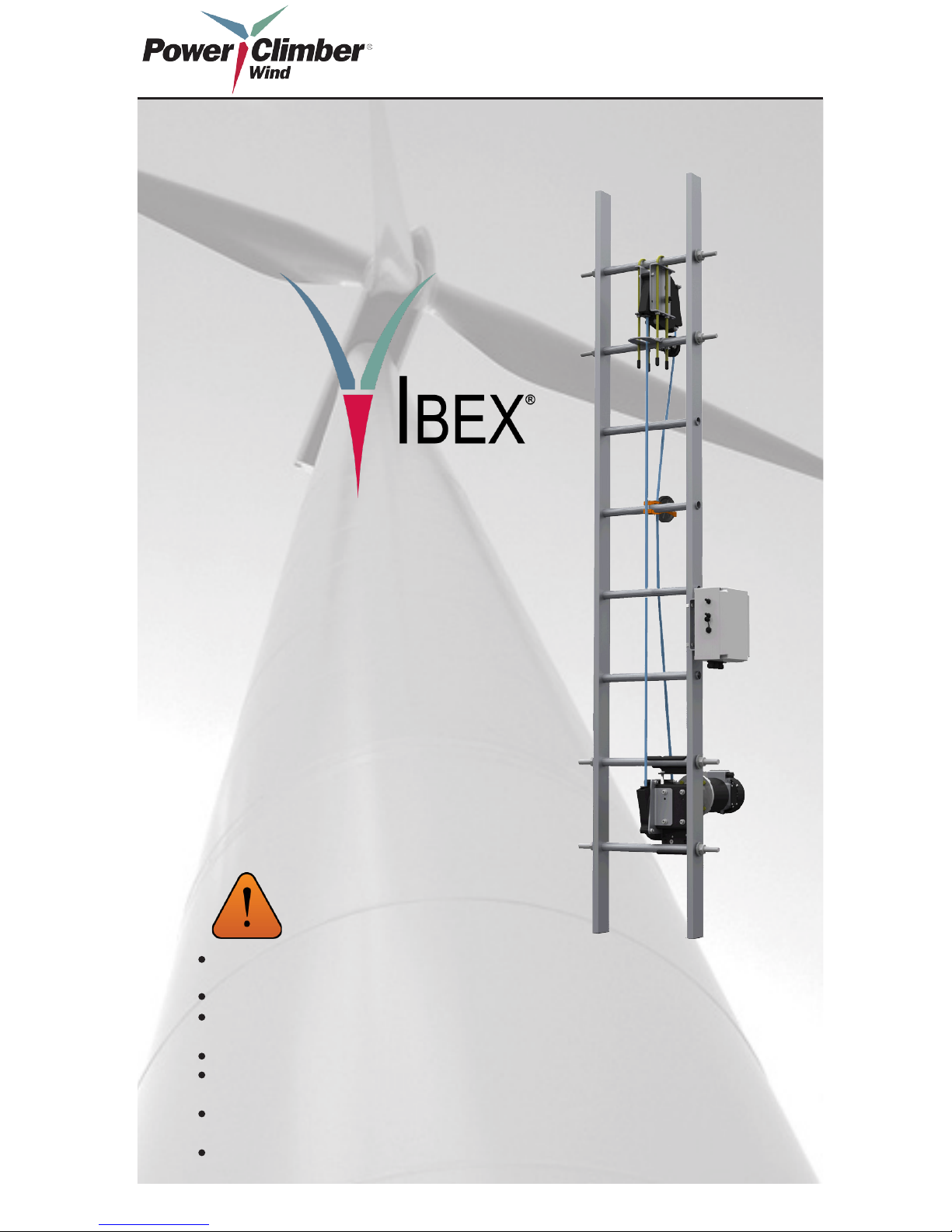
WARNING:
OPERATORS
MANUAL
IBEX® 1000 Series
The IBEX® 1000 Climb Assist System is NOT a safety device and must only be used when
user is connected to independent fall arrest system.
All personnel operating this equipment must read and completely understand this manual.
All personnel must be thoroughly trained in the use of the equipment and its operational and
safety features.
Only authorized and physically t personnel shall operate the equipment.
All persons operating this equipment must wear a safety harness at all times and tie-off as
required.
Any operation in violation of these instructions is at the operator’s own risk and may result
in serious injury.
Only use spare parts supplied by Power Climber Wind.
Climb Assist System
(Models 1050, 1065, 1080, & 1100)

Page 2 of 24
Manufacturer
Power Climber Wind
A Division of SafeWorks, LLC
365 Upland Drive
Seattle, WA 98188
Customer Support (Americas)
Tel: +1 (877) PCWIND1 (729-4631)
or outside the U.S.: +1 (206) 394-5306
Fax: +1 (206) 575-6240
Email: CustomerService@PowerClimberWind.com
www.PowerClimberWind.com
Customer Support (Europe/Asia Pacic)
Tel: +32 3 451 05 00
Email: Wind@PowerClimber.be
www.PowerClimberWind.com
Reference: 702991-1 Issue date: 26-Jan-2012 Revision: E

Page 3 of 24
Table of Contents
1. SYMBOLS USED IN THIS MANUAL ........................................................4
2. EQUIPMENT DESCRIPTION......................................................................5
2.1. General Description ..............................................................................5
2.3. Approvals ..............................................................................................5
2.2. Specications ........................................................................................5
2.4. General View.........................................................................................6
3. ASSEMBLY AND INSTALLATION INSTRUCTIONS ..............................7
3.1. Standard Components ...........................................................................7
3.2. Bottom Assembly ..................................................................................8
3.3. Upper Assembly ....................................................................................9
3.4. Belt Path Solutions ..............................................................................10
3.4.1. Pull-In Belt Rollers ....................................................................10
3.4.2. Push-Out Belt Rollers ................................................................11
3.4.3. Wear Strips ................................................................................. 11
3.5. Belt Welding........................................................................................12
3.6. Electrical Components ........................................................................12
3.6.1. Control Box ................................................................................12
3.6.2. EasyClimb Controller ................................................................14
3.7. Commissioning ...................................................................................14
3.7.1. EasyClimb Controller ................................................................14
3.7.2. Complete Installation .................................................................14
3.7.3. Ride Quality ...............................................................................14
4. OPERATION INSTRUCTIONS .................................................................15
4.1. Use of the EasyClimb Controller ........................................................15
4.1.1. To Set Level of Assistance .........................................................15
4.1.2. To Ascend ...................................................................................15
4.1.3. To Descend .................................................................................16
4.1.4. To Stop .......................................................................................16
4.1.5. To Shut Down the System ..........................................................16
4.1.6. Miscellaneous ............................................................................16
4.2. Safety ..................................................................................................16
5. MAINTENANCE INSTRUCTIONS ..........................................................17
5.1. Periodic Inspection ..............................................................................17
5.1.1. Belt Inspection .................................................................................17
5.2. Troubleshooting ..................................................................................17
5.3. Replacement of Damaged Components ..............................................18
5.4. Electrical Schematics and Wiring Diagrams .......................................19
5.5. Customer Service ................................................................................19
Page 4 of 24
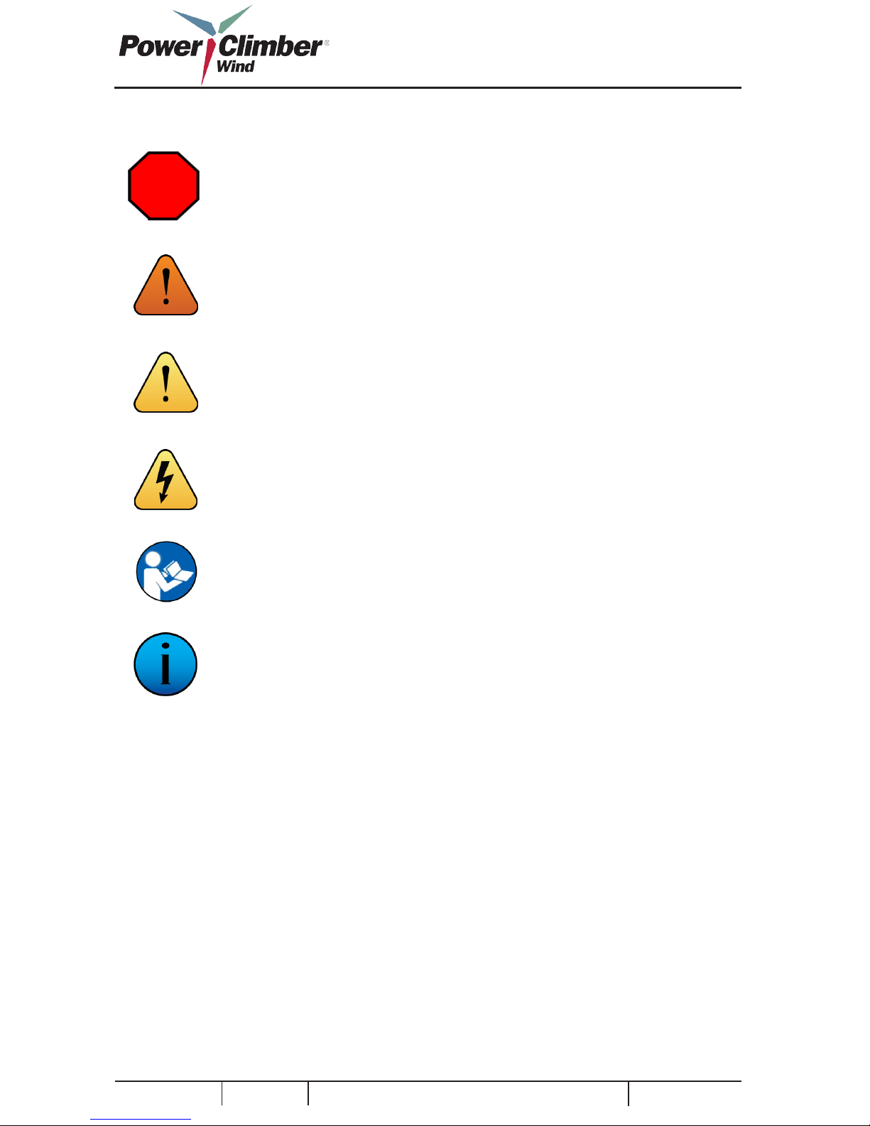
1. SYMBOLS USED IN THIS MANUAL
Reference: 702991-1 Issue date: 26-Jan-2012 Revision: E
STOP
WARNING
CAUTION
ELECTRICAL HAZARD
NOTE
INFORMATION
Stop action and follow the instructions before
continuing.
Warns against possible immediate serious injury
or death.
Warns against possible injury.
Warns against possible electrical shock hazard.
Must read this before performing any action that
follows.
Remember and take this into account.
Page 5 of 24
FCC Warning: Changes or modications not
expressly approved by Power Climber Wind for
compliance could void the user’s authority to operate the equipment.
2. EQUIPMENT DESCRIPTION
2.1. General Description
The IBEX® 1000 climb assist system is a motorized, continuous loop system that provides load
support to the climber on both the ascent and
descent. The system allows user-adjustable support settings at 50, 75, 100, and 125 pounds, and
provides constant load support regardless of climbing speed via a feedback loop between the motor
drive and load-sensing EasyClimb Controller that
attaches the climber to the belt.
The mounting system is adaptable and can be tted
to any ladder or tower with minimal adjustment
necessary (excluding the belt, which must be sized
appropriately).
The IBEX® is permanently installed on a specic
WTG ladder and consists of:
1. Top Sheave Assembly
2. Motor Assembly
3. Electrical control box
4. EasyClimb Controller (a mobile device kept by
the climber)
5. Round reinforced polymer belt and belt guides
6. Upper and lower ladder rung reinforcements
7. Belt Guide accessories
2.2. Specications
2.3. Approvals
All electrical components of the IBEX® 1000 are
UL® listed. Moving parts are guarded in compliance with OSHA 1917.151.
This device has been tested and complies with the
limits for a Class A digital device, pursuant to 47
CFR Part 15 of the FCC rules. This equipment
generates, uses, and can radiate radio frequency
energy and, if not installed and used in accordance with the instructions, may cause harmful
interference to radio communications. Operation is
subject to the following two conditions:
1 This device may not cause harmful interference
2. This device must accept any interference
received, including interference that may cause
undesired operation of the device.
Power Supply 110Vac 60 Hz; 230 Vac 50
Hz 1ø, 0.5HP Motor
10 maximum
10.5mm
IP44
Class 3
75 dBA
-35C to +40 C Operating
-40C to +60C Storage
Amperage Draw
Belt Diameter
Environmental Rating
Corrosion Protection
Noise level
Temperature Range
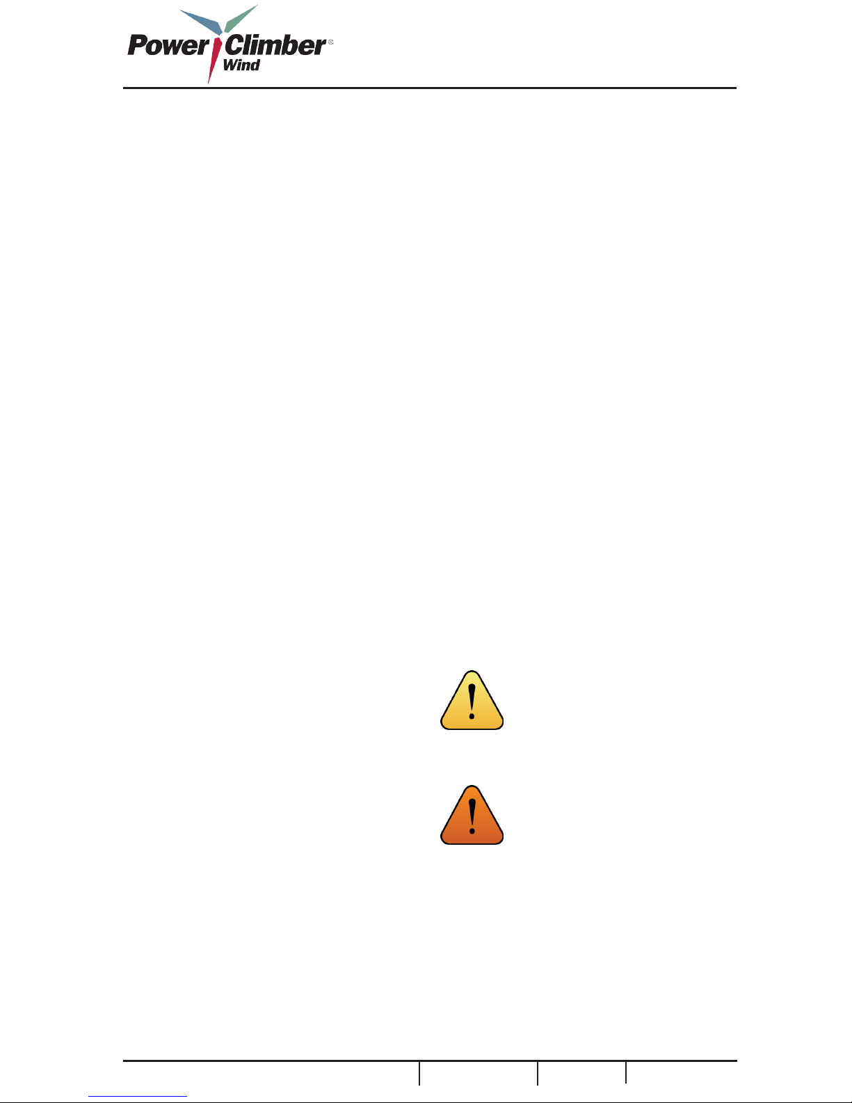
WARNING: The IBEX® 1000 climb
assist system is NOT a safety device
and must only be used in conjunction
with an independent personal fall
arrest system.
CAUTION: People with implanted
pacemakers should not use this
equipment. Radio waves could have
unexpected effects on the operation of
medical devices.
-31F to +104F Operating
-40F to +140F Storage
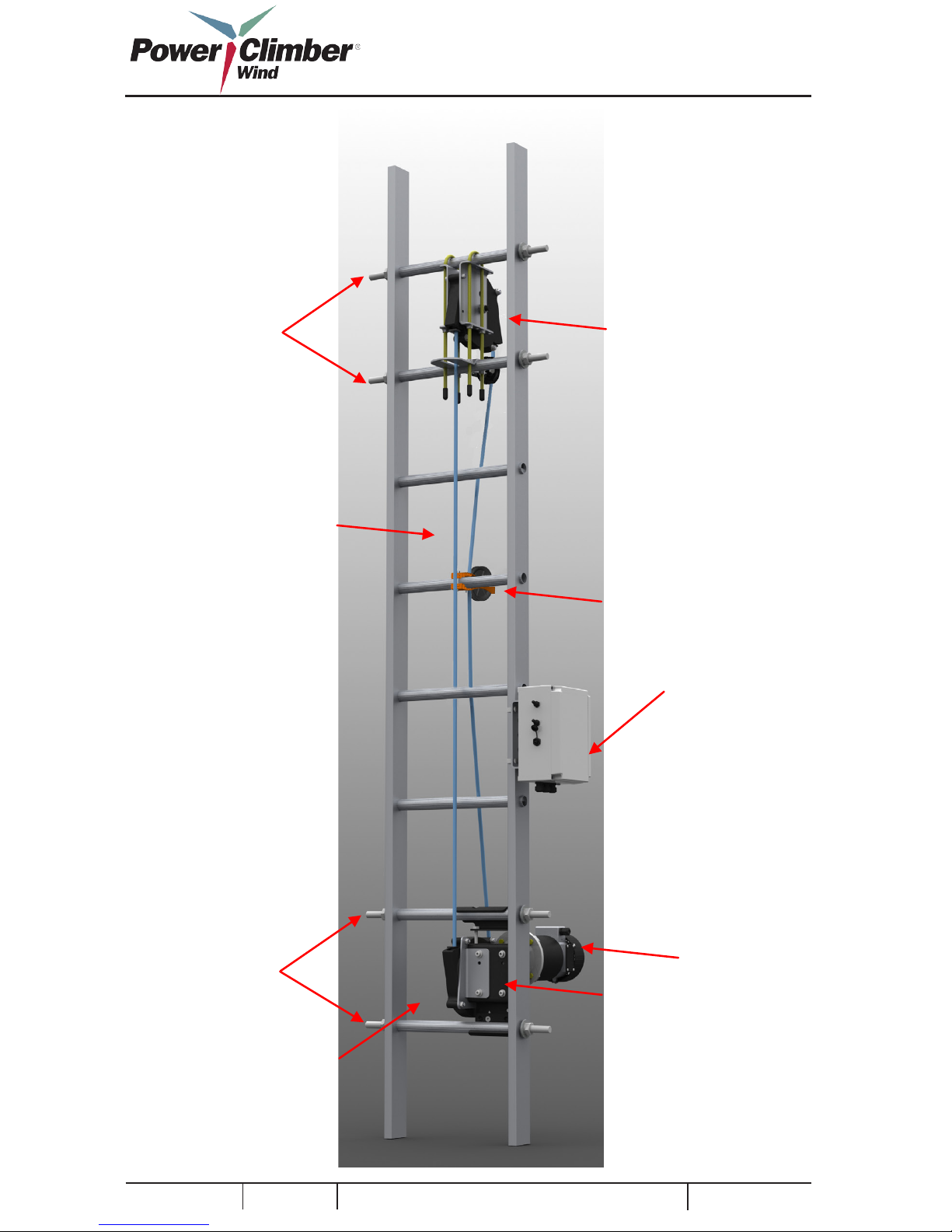
2.4. General View
Guide roller
Electrical control box
Gear motor
Motor mounting brackets
Page 6 of 24
Reference: 702991-1 Issue date: 26-Jan-2012 Revision: E
Upper rung
reinforcements
Lower rung
reinforcements
Round reinforced polymer belt
Drive sheave assembly
Top sheave assembly

3. ASSEMBLY AND INSTALLATION INSTRUCTIONS
3.1. Standard Components
The IBEX® 1000 climb assist system consists of
the following parts:
1. Top sheave assembly (1)
2. Gear motor assembly (1)
3. Electrical control box (1)
4. EasyClimb Controller (1)
5. Roller (1)
6. Roller (Model specic)
7. Upper and lower rung reinforcements (4)
8. Radio antenna and mounting bracket (1)
9. U-Bolt (2)
10. Rung Support Bracket (1)
11. Hardware kit “UPPER” (not shown)
12. Hardware kit “LOWER” (not shown)
13. Hardware kit “EXTRA” (not shown)
14. Reinforced round polymer belt, (Model specic) (not shown)
1 2 3
4
5
6
7
8
9
10
Page 7 of 24
NOTE: These installation instructions are only a guide. Each tower
can present unique complications
that must be addressed on an
individual basis. Installation of
the IBEX® requires two properly
trained technicians. Contact Power
Climber Wind to arrange for training and product support.
CAUTION: Personal Protective
Equipment (PPE) must be worn at
all times within the tower. All tools
must have lanyard attachment to a
secure location.

Fasteners:
The components of the IBEX® 1000 are assembled using standard fasteners.
All bolts should be rmly tightened. If
nylon lock nut is used, bolt thread shall
protrude passed the nylon lock nut by at
least one thread. If a lock washer is used,
bolt should be tightened to compress lock
washer at.
NOTE: Either a lock washer, star
washer or Nylok nut shall be used for
all fasteners
3.2. Bottom Assembly
NOTE: Tools Required: 17mm and
13mm Combination Wrenches, 5mm
Hex Wrench and (2) 29mm Wrenches
1
2
2. Choose the mounting position. The Bottom
Assembly requires access to two rungs. Choose
the lowest possible rungs. The IBEX® may be
installed as high as chest height before climbing is
signicantly impeded.
3. Install Rung Supports in the rungs directly
above and below the Bottom Assembly mounting
position. Thread four (4) ¾” or M20 for EU Nuts,
Lock-Washers, and Fender Washers and tighten
until Lock-Washers have been fully compressed
using 29mm Wrenches. If fall arrest system or
other rung supports are present, these may be used
if long enough to accommodate additional width.
4. Adjust Motor Assembly to t rung spacing.
Loosen or tighten 10mm shown in red Figure 3.2.1
until upper and lower brackets can clear the installation rungs.
5. Install the Motor Assembly with the brackets
ush to the ladder. Install upper bracket over rung
and tighten bolt until lower bracket is tight to
ladder.
TIP: If the fall arrest system is
mounted at the ladder center, installing the IBEX® offset from center
by up to three inches will not affect
performance.
Figure 3.2.1 Figure 3.2.2
Page 8 of 24
Reference: 702991-1 Issue date: 26-Jan-2012 Revision: E
1. Unpack the following items and arrange them
near the ladder:
Item Description Qty
1 Gear Motor Assembly 1
2 Rung Supports 2
3 Lower Hardware Kit 1
(Not Shown)

3.3. Upper Assembly
NOTE: Tools Required: 17mm
combination wrench and Two (2)
29mm Wrenches, Lift Bag capable of
holding all tools and components.
1. Unpack the following and place in the Lift Bag:
Item Description Qty
1 Upper Sheave Assembly 1
2 10mm U-Bolt 2
3 Stop Plate 1
4 Pull-In Roller MS
5 Rung Reinforcements 2
6 Roller 1
7 Upper Sheave Hardware Kit 1
(Not Shown)
1
2
3
4
5
2. Choose the mounting position. The Upper
sheave should be mounted approximately in line
with the lower sheave. The upper sheave ideally is
installed 6-7 rungs above the nal tower platform.
If the installation height is limited, care must be
taken to insure safe disengagement from the system is possible at the installed height.
3. Install Rung Supports in the rungs directly
above and below the Upper Sheave mounting
position. Thread four (4) ¾” or M20 for EU Nuts,
Lock-Washers, and Fender Washers and tighten
until Lock-Washers have been fully compressed
using 29mm Wrenches.
4. Install the Upper Sheave Assembly.
4A. Unpack the Upper Sheave, (2) U-Bolts, (1)
Rung Support Bracket and Upper Hardware
Kit Hold the Upper Sheave in place and install the
(2) 10mm U-Bolts over the top supported rung and
through the upper and lower mounting holes on the
climber side and thread on two (4) nuts with star
lock with star facing up move them up the U-Bolt.
Install (4) nuts with star lock with star facing
down. Adjust nuts up the U-Bolt to make room for
the Rung Support Bracket to t over the bottom
supported run
4B. Tighten (4) upper nuts with star lock until
the Upper Sheave Bracket is tight to the upper
supported rung. Tighten (4) lower nuts with star
lock until the Rung Support Bracket is tightly resting on the lower supported rung. Be sure the Rung
Support Bracket appears to be level in all directions and tighten evenly all (4) nuts with star lock
until Upper Sheave is rmly secured to the ladder.
4C. Install 705519-1 roller using supplied nuts.
Align holes with the U-Bolt on non-climbing side
of ladder, slide up until it is ush with stop plate.
Tighten bolts until snug.
4D. Install (4) rubber boots to end of U-Bolts.
TIP: If two rungs or less exist above
deck level, installation may be possible just below deck level. This
will require user to disconnect from
the IBEX® while on the ladder, but
connection to fall arrest system must
be maintained.
4B
4C
6
Page 9 of 24

5. Install the Pull-In Roller one rung above deck
level. Install the Pull-In Roller on top of the rung
and align with the upper sheave assembly. Install
the Rung U-Bolt with threads up and fasten with
included Nylon Locknuts. Tighten with 11mm
Combination Wrench until slight rung deformation
has occurred. As shown in image 5.
6. At the base of the ladder, lay belt on side. Pull
the belt from the center.
7. At the base of the ladder, attach the belt to the
work positioning D-ring using a carabineer and
make a loop in the belt using electrical tape wrap
12 times as shown in image 7. Climb to top of
ladder, momentarily removes the belt loop and
feed the Belt through the Upper Sheave Assembly;
then remake the loop in the rope and attach the
carabineer to the work positioning D-ring. This
person then descends the ladder normally, pulling
the Belt into position.
8. Feed the belt through the Lower Sheave and
trim to length with no overlap.
WARNING: This step denes the belt
path and care must be taken to ensure
that it is free of snags or twists around
any obstruction.
3.4. Belt Path Solutions
Ensuring a continuous belt path free of abrasion
against or possible snags around xed objects
within the tower is critical to the performance of
the IBEX® system and the life of the Belt. Below
are suggestions regarding the installation of the
standard IBEX® belt path components and additional accessories available separately.
3.4.1. Pull-In Belt Rollers
As the Belt passes through decks, there is a potential for Belt abrasion on the non-climber side. It is
recommended to install a Pull-In Roller one rung
above all decks the belt passes through. If the belt
is at an angle greater than 10°, Pull-In Belt Rollers
should be used because of the excessive force on
Rollers.
1. Unpack one (1) Pull-In Roller and one (1) Rung U-Bolt.
2. Place the Pull-In Roller on top of the installation rung, and install U-Bolt with threads facing up.
3. Install two 11mm Nuts with 11mm combination wrench. Tighten until the rung has slightly deformed.
4. After the Belt has been tensioned properly, load the belt into the belt guide.
INSTALLATION:
5
7
Page 10 of 24
Reference: 702991-1 Issue date: 26-Jan-2012 Revision: E
NOTE: Ensure belt is threaded thru
sheave inlet and exit guide piece top
and bottom.

3.4.2. Push-Out Belt Rollers
For towers with obstructions near the ladder
opposite the climber (i.e. ip-down ladder rest stations), Push-Out Belt Rollers can be used to extend
the clearance between the belt and the ladder.
Installation of Push-Out Belt Rollers is identical
to the Pull-In Belt Guides (Section 3.4.1.). IBEX®
Push-Out Belt Rollers are included with EU units
and sold separately, as required.
3.4.3. Wear Strips
Towers with safety hatches that can be closed over
the ladder way at each platform generally require
Wear Strips to prevent abrasion of the Belt against
the sharp metal of the hatch.
NOTE: Tools Required: Permanent
Marker, Pop-Rivet Gun for 1/8”
shank, #11 Drill Bit (5mm), Cordless Drill, Tape Measure
1. Unpack the following:
Item Description Qty
1 Wear Strip 1
2 3/16” Rivets 3
3 3/16” Backing Washers 3
2. With safety hatch in closed position, Mark the
ladder width on the hatch using the permanent
marker.
3. Lift the hatch and install the wear guide over the
lip of the hatch. Center the wear guide on the reference marks made in Step 2.
4. Measure 75mm (3in) in from both sides of the
Wear Strip and mark with Permanent Marker. Drill
#11 hole 12mm (0.5in) from edge of hatch at those
marks through Wear Strip, Hatch, and Wear Strip
Back. Install the two 3/16” Rivets with Rivet Gun.
NOTE: To accommodate the widest possible range of wind turbine
tower designs and specications, the
IBEX® system is offered with easily
adaptable solutions, which can be
ordered on an individual basis or in
tower specic kits. Contact Power
Climber Wind to receive a Tower
Survey form and to discuss which
components are needed for your
installation.
Page 11 of 24

1 2 3
Page 12 of 24
NOTE: Tools Required: 13mm
Combination Wrench, 6mm Hex
Wrench, 11mm Combination
Wrench, 7mm Nut Driver, Flathead
Screwdriver
Reference: 702991-1 Issue date: 26-Jan-2012 Revision: E
3.6. Electrical Components
TIP: Complete this section during
the 25 minute wait for the weld to
be complete
1. Unpack the following components:
Item Description Qty
1 Electrical Control Box 1
2 Antenna and Bracket 1
3 Pipe Clamps 2
3.6.1. Control Box
3.5. Belt Welding
Refer to belt tensioning, welding, and qualication
procedures. Only persons trained and qualied by
PowerClimber Wind shall complete belt installation.

2. Mount the Electrical Control Box to the ladder
and tighten the Pipe Clamps using the Flathead
Screwdriver.
3. Remove the Motor Electrical Cap from the Motor with a Flathead Screwdriver.
4. Open the Cable Gland and feed the power wires
with the ring terminals through the gland.
5. Loosen screws and connect the black wire to
the positive contact post (A) and the white wire to
the negative contact post (B). Tighten to hand tight
using the athead screwdriver.
6. Remove the green grounding screw located on
the outside of the enclosure and attach the green
wire to the bung (C) inside the enclosure. Tighten
with a Flathead Screwdriver.
7. Re-Install the Motor Electrical Cap and tighten
the screws with the athead screwdriver. Tighten
the Cable Gland until snug.
8. Route the AC Power Cord to a standard outlet
(120/220 VAC). Make sure the AC Power Cord is
hidden and secured with cable ties a minimum of
every three (3) feet. If the AC Power Cord is too
long bundle the cable into a loop and Cable Tie in
place.
TIP: If a clear path to the outlet
is not present, a 30mm (1.25in)
hole can be drilled in the platform
directly below the Electrical Control
Box when authorised by an On-Site
Competent Person.
9. Install the Antenna to a convenient location.
The antenna must be installed between vertical
and forty-ve degrees and must not be within the
ladder path or material hoist paths. Mounting loca-
tions must be evaluated on a tower-specic basis.
10. Run the Antenna Cable in a manner identical
to Step 8.
NOTE:
• Routing of the AC Power Cord
from the Electrical Control Box to a
standard outlet (120/220 VAC) must
be approved by the turbine owner or
representative.
• The AC Power Cord shall be routed
so as to avoid interference with normal operation of other components
or moving parts within the turbine
tower, and to avoid any trip and fall
or other hazard to personnel moving
within the turbine tower.
• If the AC Power Cord is routed
above the platform deck in areas of
foot trafc, it must be protected using
crush-resistant tubing. Alternatively,
it may be possible to route the AC
Power Cord beneath the platform
deck with owner approval.
• The AC Power Cord should be
secured in place every three feet
(1 meter) using nylon cable ties or
equivalent.
• Contact of the AC Power Cord
against any unprotected metal edges
(i.e., cut diamond plate) should be
avoided. Grommets or other protection should be used as required.
A
B
C
Page 13 of 24
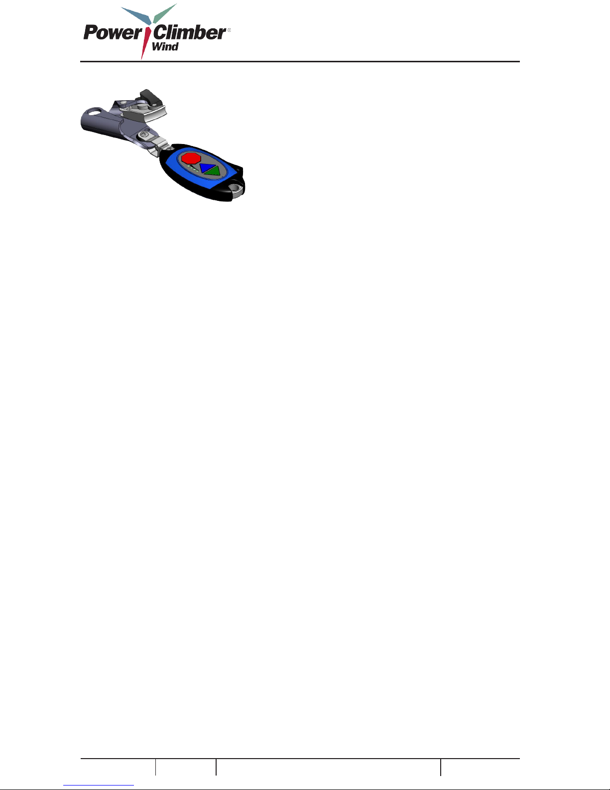
3.6.2. EasyClimb Controller
The EasyClimb Controller assembly includes an
integrated rope grab and carabineer to connect it to
the user’s harness at the front D-Ring. The EasyClimb Controller must be charged for 24 hours
using the enclosed 12Vdc wall transformer. When
not in use the EasyClimb Controller may be safely
placed on charge for an unlimited period.
3.7. Commissioning
3.7.1. EasyClimb Controller
1. Review section 4.1 below on the operation of the
EasyClimb Controller.
2. Press STOP: verify all 4 LEDs ash once.
3. Press and hold STOP, press UP: verify one LED
ashes and sequentially cycles in the up direction.
Release STOP.
4. Press and hold STOP, press DOWN: verify one
LED ashes and sequentially cycles in the down
direction. Release Stop.
5. Wait at least 30 sec. after last button operation
then repeat 2.
3.7.2. Complete Installation
(Do not connect EasyClimb Controller to belt)
6. Verify belt tension is set according to the table
in section 3.5.
7. Connect power to the unit.
8. Set key to Inspect and turn on the power: Verify
that the belt runs down (at nominally 60 fpm)
9. Set key to run. Verify belt stops. Cycle power.
10. Press Up (EasyClimb Controller): Verify belt
runs up slowly for 2 to 3 seconds.
11. Set EasyClimb Controller to 50 lbs in UP and
DOWN direction.
12. Attach rope grab to safety wire.
13. Apply a load to the harness attachment point of
the EasyClimb Controller.
14. Press UP (twice if needed): Verify that the belt
moves up at a speed that varies inversely with the
load applied to the EasyClimb Controller.
15. While load is applied and the belt is running,
press STOP: Verify that the belt stops and does not
respond to load.
16. Press the DOWN button (twice if needed).
17. Apply a load to the EasyClimb Controller
(there may be a short delay in start): Verify that
the belt moves down at a speed that varies with the
load applied to the EasyClimb Controller.
18. Take all load off the EasyClimb Controller.
Verify that the belt stops, and restarts if load is
reapplied within 10 seconds, otherwise remains
stopped.
19. While load is applied, press STOP: Verify that
the belt stops and does not respond to load.
20. Angle the EasyClimb Controller down and
press UP multiple times: Verify that the belt
remains stationary.
3.7.3. Ride Quality
21. Cycle the power switch to ensure the system
is reset.
22. Connect the rope grab to the belt and the carabineer to the harness.
23. Test ride to ensure proper function of system.
Page 14 of 24
Reference: 702991-1 Issue date: 26-Jan-2012 Revision: E
After Installation is complete, carry out the following steps to commission the installed IBEX® 1000
climb assist system.

4. OPERATION INSTRUCTIONS
WARNING: The IBEX® 1000 climb
assist system is not a safety device and
must only be used in conjunction with
an independent personal fall arrest
system.
4.1. Use of the EasyClimb Controller
UP
DOWN
STOP
4.1.1. To Set Level of Assistance
1. Press and hold the STOP button while:
a. Press and release the UP button to set the
desired level of assistance for ascent;
b. Press and release the DOWN Button to set
the desired level of assistance for descent.
2. When the desired levels are set, release the
STOP button.
3. At rst press, while the STOP button is held, the
indicator shows the current setting.
4. With further presses, the indicators will cycle.
NOTE: To ensure safe operation of
the system;
• Pressing the STOP button prevents
the assist motor from operating while
setting levels.
• Assist levels cannot be set during
motor operation. Press STOP before
attempting to change assist level
settings.
• Assist levels are retained after setting.
NOTE:
• If the level of assist does not reach
9.07 klg. (20 lbs) within 1 second, the
motor will stop. Restart by pressing
the UP button as above.
• A stop delay is included and is preset
to 10 seconds.
• The LED will show the selected
level of assist during the climb.
CAUTION: When reaching the top
of the ladder, be sure to press the
STOP button three feet before the rope
grab reaches the stop plate on the Upper Sheave Assembly.
Page 15 of 24
4.1.2. To Ascend
1. Couple the EasyClimb Controller between the
harness chest ring and the rope grab clipped to the
belt.
2. Press and release the UP button. The indicator
ashes to show the set level of assist.
3. The belt will slowly start.
4. When the assist is felt, begin climbing up.
5. To stop, stop climbing then press the STOP but-
ton, or press the STOP button rst.

4.1.3. To Descend
1. Connect the EasyClimb Controller between the
harness chest ring and the rope grab clipped to the
belt.
2. Press and release the DOWN button. The indica-
tor ashes to show the set level of assist.
3. Begin climbing down.
4. To stop, stop climbing or press the STOP button.
NOTE:
• If the load in the EasyClimb Controller does not reach 9.07 klg. (20
lbs) within 15 seconds, the motor will
stop. Restart by pressing the DOWN
button as above.
• The LED will show the selected
level of assist during the climb.
4.1.4. To Stop
1. Press the STOP button to stop immediately.
NOTE: You may have your weight
on the EasyClimb Controller before
pressing UP or DOWN
4.1.5. To Shut Down the System
To shut down the system, put the power switch
located on the electrical control box in the OFF position. Although not neccessary it is recommended
to unplug system when not in use.
4.1.6. Miscellaneous
4.2. Safety
Often, during the ascent, it is necessary to momentarily stop, for example to open or close a hatch.
For convenience, a delay is automatically set when
the climber stops climbing and the climber remains
supported. Provided the ascent resumes within 10
seconds, it is not necessary to press the UP button
again, otherwise press UP and resume the ascent.
Similarly, during descent, the climber may stop for
a delay of 10 seconds before resuming the climb
before it is necessary to press the DOWN button.
Otherwise press DOWN and resume the descent.
Because the climber is remote from the motor
controls, and to ensure that the system responds to
the climber’s intentions and does not operate fro m
unintended actions, it is necessary to press the UP
or DOWN button to initiate a climb.
To ensure that operation of multiple EasyClimb
Controllers does not cause unexpected actions,
each EasyClimb Controller has a unique serial
number. Concurrent operation of more than one
EasyClimb Controller in a tower may cause the
motor to stop and remain stopped for 30 seconds.
To prevent erroneous operations, it is only possible
to communicate with the motor drive while the
EasyClimb Controller is pointed up.
Page 16 of 24
Reference: 702991-1 Issue date: 26-Jan-2012 Revision: E

5. MAINTENANCE INSTRUCTIONS
The IBEX® 1000 requires minimal maintenance.
All bearings are sealed and do not require lubrication
5.1. Periodic Inspection
5.1.1. Belt Inspection
As a moving part, the round assist belt is subject
to wear with use. Visual inspection of the belt
for abrasion or other damage or weld separation
should be performed regularly. Closer inspection
of the entire belt length should be performed once
annually. Setting the lower switch on the electrical
control box to INSPECT will engage the maintenance mode. In this mode, the motor will drive
the belt at a slow speed. While at the ladder base,
allow the belt to pass through the inspector’s hand
while also visually inspecting the belt as it moves.
Surface scarring from use of rope grabs is normal
and will not affect performance or safety of the
belt. However, if excessive scarring or abrasion
against the ladder or platforms is discovered, the
worn section may be removed and a replacement
section spliced into place according to the belt
splicing procedures in section 3.5.
5.2. Troubleshooting
Belt slips on the drive sheave
• Check for oil on the belt or drive sheave. Use a
dry cloth to clean the belt using maintenance mode.
•Will occur if the belt tension is too low during
installation. See tension table in section 3.5.
EasyClimb Controller LEDs do not indicate
• Place the EasyClimb Controller on the charger
for at least 24 hours
Belt stops when the EasyClimb Controller is in the
upper zone of the tower
• Verify that the antenna is connected, correctly
aligned and is not damaged.
• Ensure that the EasyClimb Controller is pointing
up with the stop button highest.
Belt will not respond to controller commands
• Check to see if a second EasyClimb Controller is
causing interference.
Belt stops at random times and will not operate
again for 30 seconds
Symptom Consider
Page 17 of 24

5.3. Replacement of Damaged Components
WARNING: Only use parts supplied
by Power Climber Wind. Use of
non-authorized parts will void the
warranty.
Service of the EasyClimb Controller and electrical
control box shall be performed by Power Climber
Wind by factory return. During the warranty
period a replacement controller or control box will
be supplied if required.
NOTE: See the spare parts list in section 5.5 for replacement items.
Page 18 of 24
Reference: 702991-1 Issue date: 26-Jan-2012 Revision: E
NOTE: Replacements are to be made
following the installation procedure
detailed in section 3.

Page 19 of 24
5.4. Electrical Schematics and Wiring Diagrams
115Vac
220 Vac
ANT.
90V PMDC
W B
G
5.5. Customer Service
For service requests or spare parts orders, contact Power Climber Wind Customer Service in the U.S. or
Canada at CustomerService@PowerClimberWind.com or via telephone inside the U.S. at +1 (877) PC-
WIND1 or outside the U.S. at +1 (206) 394-5306. In Europe/Asia Pacic call +32 3 451 05 00 or e-mail
Wind@PowerClimber.be

C
2012 Power Climber Wind
A division of SafeWorks, LLC
702991-1 Rev. E
 Loading...