

Page 1
Operating Instructions
Page 2

Page 3

Smart-Switch
- 3 -
Dear customer,
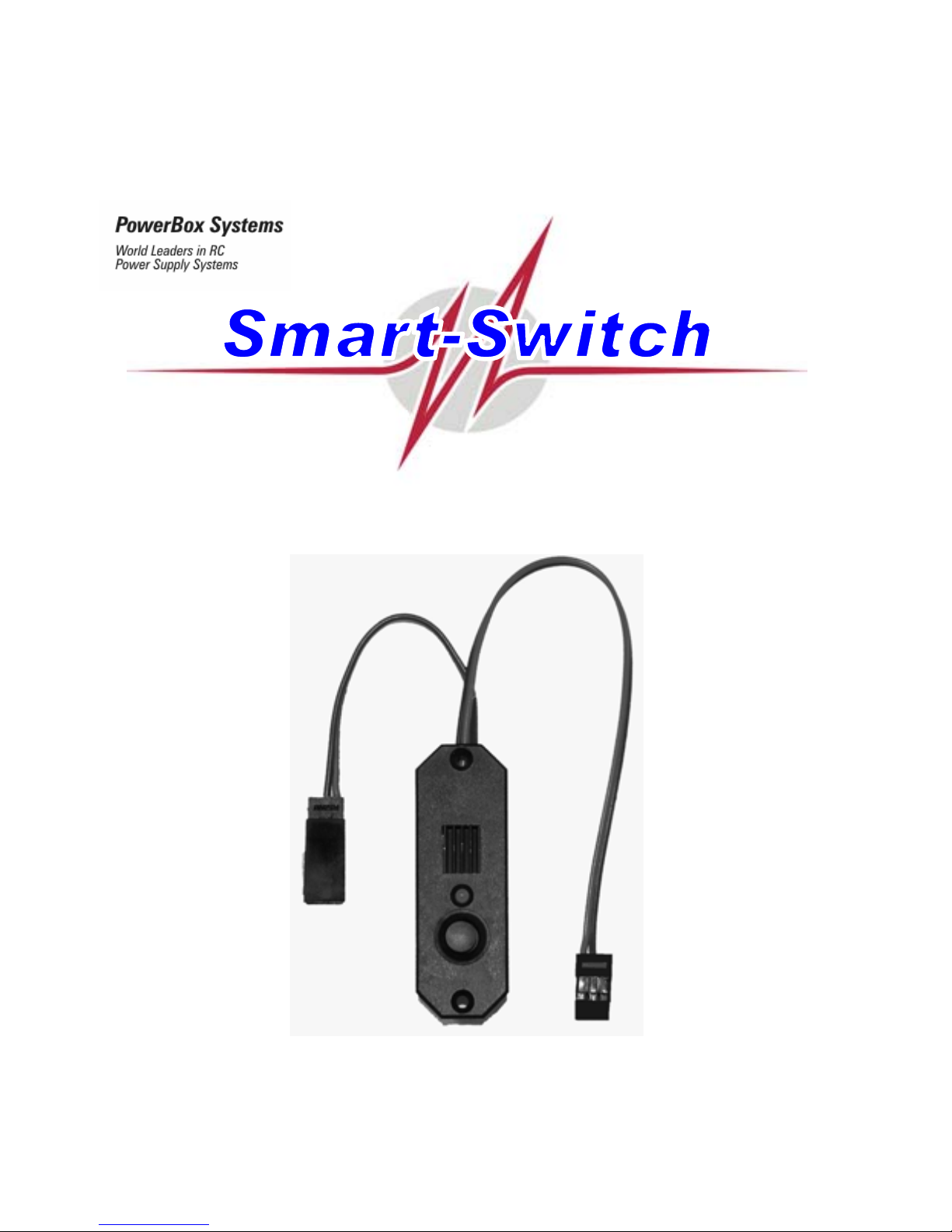
Congratulations on your decision to purchase the Smart-Switch from our range!
This innovative product is the world’s first electronic multi-function switch system,
developed and produced by PowerBox Systems GmbH. The unit is designed to switch the
receiving system on and off safely and reliably, and to monitor the airborne power supply.
The switch housing accommodates a modern, failure-proof electronic switch and a fourstage voltage monitor designed for use with all the usual power sources employed in
modeling: four-cell and five-cell NC or NiMH batteries, and two-cell LiPo packs.
The dual connecting leads have a conductor cross-section of 0.34 mm², and inside the
elegant, extremely robust plastic housing they are both soldered directly (i.e. in a straight
line) to extra-wide solder pads, where they are enca sed in a special support adhesive for
additional protection from possible vibration damage.
We recommend the Smart-Switch primarily for the following applications and types of
model:
- all models which were previously equipped with mechanical switches,
- small to medium-sized model aircraft,
- model gliders,
- model helicopters
- model cars,
- model boats, and
- all kinds of petrol engine ignition
Page 4

Smart-Switch
- 4 -
Operation:
The only control on the Smart-Switch is the push-button, whic h makes it e xtremely eas y to
use. All this button does is pass the s witch signal to the electronic switch; it has no thing to
do with the actual switching of the current.
Connect a battery of your choice to the battery lead, which is fitted with a Universal
connector (JR, Futaba). The pack may be a four-cell o r five-cel l NC or NiMH t ype, or a t wocell (7.4 V) LiPo or Li-Ion battery. Take care to connect the pack with correct polarity.
Caution: the Smart-Switch does not feature a voltage stabilization circuit.
If you wish to use a two-cell LiPo battery, you must not use the Smart-Switch in
conjunction with a receiving system designed only for 6.0 Volts, i.e. the entire system receiver and servos - must be de signed to cope with this voltage. If the rec eiving system is
only designed for max. 6.0 Volts, we recommend the Digi-Switch (also in our range), as
this features a supplementary voltage stabilization circuit which generates 5.5 Volts; the
switch housing is the same size.
If the Smart-Switch is to be used with a two-cell LiPo pack, one application which we
particularly recommend is as a switch for ignition systems which are designed as standard
for more than 6.0 Volts.
Caution: connecting the battery with reversed polarit y will destroy the switching IC
inside the unit!
When you connect the correct battery, the LED immediately glows green.
By default the voltage monitor is set up for use with LiPo cells.
If you wish to use an NC or NiMH battery, you must first re-set the voltage monitor circuit,
otherwise the unit will detect the wrong battery type, and the LED will constantly flash red.
Page 5

Smart-Switch
- 5 -
The voltage monitor setting is changed u sing the sensor butto n. You simply hold th e button
pressed in until the LED indicates the correct setting in setup mode:
- LED flashes green once = LiPo
- LED flashes green twice = five-cell battery
- LED flashes green three times = four-cell battery
Now we come to the procedure for setting the voltage monitor circuit:
- Hold the sensor button pressed in
- After about one second the color of the LED changes to orange
- After a further three seconds the color of the LED changes to red
- After a further five seconds the LED goes out briefly - now watch carefully!
- The LED emits one brief green flash: rel ease the button now, and the switch is s et to
voltage monitoring for LiPo batteries.
- If you continue to hold the button pressed in, the LED emits two brief green flashes:
release the button now, and the switch is set to volta ge monit oring for a fi ve-cell N C or
NiMH battery.
- If you still continue to hold the button pressed in, the LED emits three brief green
flashes: release the button now, and the switch is set to voltage monitoring for a f ourcell NC or NiMH battery.
Page 6

Smart-Switch
- 6 -
To switch off: hold the sensor button pre ssed in for about 0.5 seconds until the LED glo ws
orange, then press the button briefly a second time. The LED goes out, and the Smart-
Switch is switched off.
To switch on: hold the sensor button pressed in for about 0.5 seconds until the LED glo ws
orange, then press the button briefly a second tim e. The LED glows green, and the s witch
is on.
The process of pressing the button twice, with a precisely defined interval, eliminates the
possibility of the switch being turned off accidentally, e.g. by vibration.
If the LED glows orange or red instead of green when you switch the circuit on, this
indicates that the battery connected to it is not fully charged or is already discharged;
alternatively the incorrect battery type might have been set. If this should occur, we
recommend that you recharge the pack using a suitable battery charger before using it
again; alternatively set the switch to the correct battery type.
The current handling capacity of the Smart-Switch stated in the Specification does not
relate to the switching capacity of the electronic switch, but to the limitations of the two
connecting leads (conductor cross-section 0.34 mm²) and the gold-plated Uni connector
contacts (JR, Futaba). Cooling is not required with the Smart-Switch. In electronic terms
the switching capacity of the Smart-Switch is more than 20 A, and if the current should
approach anywhere near this value, the leads and th e Uni-connector would burn out long
before the switch was affected.
If the Smart-Switch is left connected to a battery when it is switched off , the unit goes into
“stand-by” mode. The idle current in this state is around 5.0 µA, which is lower than any
battery’s natural rate of self-discharge. Even so, we recommend that you disconnect the
battery from the switch if you know the model will not be used for a long period.
Please don’t just throw away the inner packaging, as it is designed to be used as a
template for marking the switch aperture on the model. Cut the opening using a knife or
saw, working slightl y outside the marked line (see photo).
Page 7

Smart-Switch
- 7 -
Even though our product is very well protected >from the effects of vibration, the Smart-
Switch should always be mounted in a part of the model where vibration levels are
relatively low.
Please note the following point:
The GRP fuselage sides of a large powe r model are not suitable for mounting the SmartSwitch - nor any other type of switch - as they are always subject to considerable vibration.
You can remedy the situation by cutting a ply plate (2.5 - 3 mm thick) about 2 - 3 cm larger
than the switch aperture, and gluing it over the inside of the opening.
The plate damps the vibration, and at the same time provides plenty of “meat” for the switch
retaining screws to bite into.
Page 8

Smart-Switch
- 8 -
The difference between the Digi-Switch and the Smart-Switch
The Digi-Switch features a linear IC-controlled regulator which maintains the voltage for
the consumer units - receiver and servos - at a constant 5.5 Vo lts, regardless of the batter y
to which you connect it. Externally the Digi -S witch is disting uish ed b y the black he at- sink on
the front face, and the silver heat-sink on the rear of the housing.
The Smart-Switch does not feature an integral regulator, i.e. the input voltage from the
connected battery simply passes through it just like any other switch; the voltage is not
regulated or reduced in any wa y. For this reason, i f the Smart-Switch is connected to LiPo
cells, it must not be used in conjunction with a recei ving system which is designe d for max.
6.0 Volts, as this would subject the recei ver and servos to an input voltage which could be
as high as 8.4 Volts. Externally you can di stinguish the Smart-Switch by the blue heat-sink
on its front face; there is also no heat-sink on the rear of the housing.
For your receiver power supplies we parti cularl y recomme nd o ur o wn make of batte ries: th e
PowerBox Battery 2800 or PowerBox Battery 1500. These packs feature an integral
electronic monitor / security circuit to ensure reliable chargi ng, and each battery is supplie d
complete with a practical mounting frame.
We are also delighted to make up NC or NiMH batteries to your own specification.
If a separate charge lead is fitted to the battery, you can safely leave the Smart-Switch
connected to the pack while it is on charge, but it must be in the switched-off state.
Important: switch the Smart-Switch off!
During the in-house production process each Smart-Switch undergoes a series of tests.
We take the maintenance of high quality standards very seriously, and this includes boughtin items. That is why we are able to grant a 24 month guaran tee on all our battery backer
and switch systems.
Page 9

Smart-Switch
- 9 -
The guarantee covers proven material faults, which will be corrected by us at no charge to
you.
Misuse and maltreatment, such as re versed polarity connecti ons, excessi ve voltage, damp,
external mechanical influences or damage (crash damage) or inappropriate mounting
(serious vibration) invalidate the guarantee.
The guarantee does not cover any additional claims, such as conseq uent damage. We do
not accept liability for damage which is caused by the unit or its use, because we are
unable to ensure that it is installed and operated in accordance with our instructions.
Specification :
Voltage range : Four-cell or five-cell NC or NiMH battery
Two-cell LiPo or Li-Ion battery
Output voltage: According to battery type in use
Switching capacity: More than 20 Amps. In practice the limiting factor is the connecting
cable and connector contacts
Weight: 15 grammes, including cables
Temperature range : - 10°C to + 75°C
Accessories:
• Retaining screws
• Installation template
Order No.: 6510
Page 10

Smart-Switch
- 10 -
We wish you every success using your new Smart-Switch from the PowerBox S ystems
range, and hope you have loads of fun with it.
Donauwörth, December 2006
PowerBox-Systems GmbH
Ludwig-Auer-Strasse 5
86609 Donauwörth, Germany
Tel: +49-906-22559
Fax: +49-906-22459
info@PowerBox-Systems.com
www.PowerBox-Systems.com
 Loading...