

PowerBox Systems PowerPak Series, PowerPak 2.5X2 ECO, PowerPak 2.5X2 PRO, PowerPak 5.0X2 PRO, PowerPak 2.5X3 PRO Instruction Manual

Instruction Manual
PowEr PAk
PowerPak 2.5X2 ECO | PowerPak 2.5X2 PRO
PowerPak 5.0X2 PRO | PowerPak 2.5X3 PRO

2
PowerBox-Systems − World Leaders in RC Power Supply Systems
Dear PowerBox pilot,
We are delighted that you have chosen a power supply system from the Po-
werPak series. These high-quality energy storage units combine maximum
power density and security in a rugged, compact case. PowerPaks are very
exible: thanks to the mounting frame supplied as standard, they are easy to
install, and can be swapped between models.
The PowerPaks 2.5X2 are available in two versions: ECO and PRO. The two
variants differ only in the charging technology – the performance of the cells
is always the same. The PRO version features integral charging circuitry and
a voltage monitor, whereas the ECO version is charged using a conventional
Li-Ion charger. Balancers are standard in both versions.
The self-discharge feature originally tted is to be discontinued as of Winter
2018, this function is now handled by the supplied BattLife Guard!
We hope you have years of pleasure and success with your PowerPak.
FEATURES:
integral charge / security electronics (PRO version)
can be charged using mains PSU or 12 V adapter (PRO version)
integral voltage monitor using external LED (PRO version)
Packs assembled using the latest generation of high-current
Li-Ion batteries
two different versions: ECO and PRO
two different output voltages: 8.4 V and 12.6 V
maximum discharge current 30 A
for use as receiver power supplies or turbine batteries
integral balancer
integral charge socket
rugged case protects cells from external inuences
Packs are held securely in the standard mounting frame with
quick-release latch
Batteries can remain in the model for charging
easy, swift battery swapping
economical cell exchange service

www.powerbox-systems.com
3
1. INSTALLATION, CONNECTIONS
PowerPaks are installed in the model using the mounting frame, which
should be attached to a surface in the model which is as rigid as possible. Fit
the rubber grommets and brass spacers as shown in the illustration below:
TIP: For best
support put the
atten side down!
top
bottom
CONTENT
1. Installation, connections .......................................................................................3
2. Charging ...................................................................................................................5
3. Cell care ...................................................................................................................7
4. Voltage indicator, PRO version ............................................................................7
5. Cell exchange, Service ...........................................................................................8
6. Specication ............................................................................................................8
7. Dimensions...............................................................................................................9
8. Set contents .......................................................................................................... 10
9. Service .................................................................................................................... 10
10. Guarantee conditions .......................................................................................10
11. Liability exclusion ..............................................................................................11
4
PowerBox-Systems − World Leaders in RC Power Supply Systems
It is important to bear in mind that high G-forces and severe vibration can
occur in our models. This means that the mounting surface has to be capable
of withstanding several times the weight of the battery. The three-point arrangement of the mounting frame’s retaining screws allows the PowerPak to be
installed on surfaces which are not absolutely at.
The PowerPak is connected to the consumer unit using the patch leads (MPX
/ JR or MPX / MPX) supplied in the set. It is important that no substantial
length of cable should lie loose in the model, as this could place mechanical
strain on the connections.
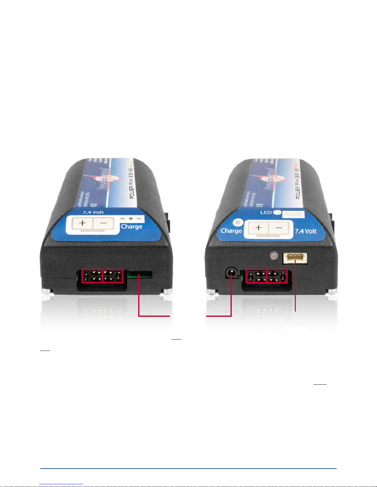
Connections for the two versions - ECO (left) and PRO (right):
Note: PowerPaks are available in 2s form for receiver power supplies, and in
3s form for turbine power supplies.
Do not confuse the two versions! If you accidentally connect a PowerPak x3
to a receiver, the high voltage will destroy the electronics. To help you differentiate between the versions, the front of the PowerPak x3 is marked red.
2. CHARGING
PowerPak 2.5X2 is available in two versions: PRO and ECO; the basic diffe-
rence between the types is the method of charging. The PRO version has its
own integral charge circuit, matched specically to the installed cells, whe-
Charge
+
-
external LED
+
-
 Loading...