

PowerBox Systems Mercury SRS Instruction Manual

Instruction Manual
04/2016
SrS
®

-02-
Dear customer,
We are delighted that you have decided to purchase the PowerBox
Mercury SRS power supply from our range. We hope you have many
hours of pleasure and great success with your PowerBox Mercury SRS.
Product description
The PowerBox Mercury SRS is a new power management system which
combines all the experience and findings we have gained over the last few
years, together with customer requests, in a single compact unit. Never
before has so much functionality been crammed into such a small space!
The Mercury SRS is ideal for any application requiring an airborne system
which provides an uncompromising level of high performance. Integral
iGyro, dual battery, dual receiving system, telemetry, door sequencer and
servo matching are just a few of the highlights which this small, lightweight
device provides.
Introduction
These instructions explain how to install the Mercury SRS in the model
and set it up with the help of the Assistants. Working through the individual
steps in the Assistants completes most of the programming for the model;
all that remains is to set up the auxiliary functions and fine-tune the servos
using the servo-match function. Naturally it is also possible to set up all the
functions of the Mercury SRS manually, i.e. without using the Setup
Assistant. All the menu points are explained individually in the latter part of
these instructions.
1. Using the unit for the first time
Any pilot who has experience using a PowerBox will immediately feel ‘at
home’ with the method of operating the Mercury SRS. The device is
operated in the usual way with the help of a menu system displayed on the
OLED screen, and the ON / OFF switch.
1.1. Installing the Mercury SRS in the model
The Mercury SRS must be screwed to a hard surface in the model,
otherwise it is possible that the integral iGyro will not work properly. If the
mounting plate is large, it must be stiffened by the addition of cross-struts.
Please note that the Mercury SRS must always be installed in the model

-03-
at right-angles to the fuselage centreline. The actual orientation of the
Mercury SRS is unimportant: it can be installed in any location which is at
90° to the direction of flight. The actual installed position is automatically
detected later when the Assistant is invoked.
The switch is mounted on the fuselage side. As is usual, the inside of the
switch opening should be stiffened by adding a hardwood doubler to
prevent serious vibration from reaching the switch; this is particularly
important if the fuselage is made of GRP. In the case of scale models it is
often undesirable to have an exposed switch on the outside, and for such
applications we offer the MagSensor or the Magic Jeti Switch (only Jeti
TX) as alternative methods of switching. Please note, however: the
Sensor Switch is essential for programming the unit, and should always
be accessible.
The OLED screen can be installed in any location where it is clearly
visible. If the standard cable (50 cm) is not long enough, we can supply
extension leads.
1.2. Connections
The first step in operating the PowerBox is to connect two batteries to it;
the two packs should be of the same type and capacity. Connect the
switch, the screen, both receivers (Spektrum system: four satellites) and
the optional GPS II sensor using the patch-leads supplied in the set. The
batteries can be either 2S LiPo, 2S LiIon, 2S LiFePo or 5S NiMH types.
We recommend the use of PowerBox Batteries, which include integral
electronic charge circuitry. If you intend to make up your own battery
packs, please note that correct polarity is vital, as the unit does not include
reverse polarity protection in order to avoid power losses.
Connecting a battery with reversed polarity - no matter how briefly will instantly destroy the voltage regulators in the PowerBox.
1.3. Switching on
This is the procedure for switching the PowerBox on: hold the SET button
pressed in, and wait until the orange LED on the switch lights up. Continue
to hold the SET button pressed in while you briefly press buttons I and II;
this completes the switching process. The OLED screen now displays the
following:
-04-
2. Menu
Hold the SET button pressed in for two or three seconds to enter the menu
system; you can now move the cursor using buttons I and II. Hold the SET
button pressed in once you have selected a particular menu point; you can
then adjust values and settings using buttons I and II.
3. Basic settings
3.1. Selecting the radio control system
The Mercury SRS must be informed which radio control system you wish
to use, as the bus systems of the various manufacturers differ very widely.
You only need to enter this information once.
The unit’s integral SRS system selects one receiver when switched on,
and automatically switches over to the second receiver if the signal is lost.
Regardless of the type of radio control system employed, the change-over
process takes just a few milliseconds, and is not noticeable to the pilot.
The Mercury SRS can also be operated with a single receiver.
Select the GENERAL SETTINGS point at the main menu, then press the
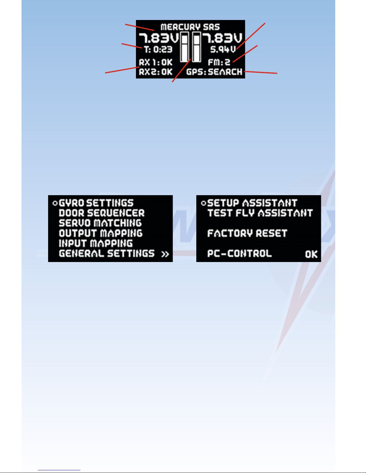
SET button; the following screen display appears:
Digital battery display
Flight time since the
last reset
Receiver status
Voltage display in bar form showing also low voltage
threshold to display voltage drops
Output voltage
iGyro flight mode
GPS status

-05-
At this point please select the radio control system you wish to use. With
most receivers it is necessary to activate the Bus output, and / or set the
correct operating mode. Bear in mind the following points:
- Futaba FASST und FASSTEST
The Mercury SRS works with the S-BUS signal. Many receivers require
one output to be re-assigned to S-BUS:
• R7003SB: no adjustment necessary; signal present at “PORT 1”.
• R7008SB: output 8 must be set to S-BUS, Mode B or Mode D.
• R6303SB: no adjustment necessary; direct S-BUS output fitted
• R6308SB(T): output 8 must be set to S-BUS, Mode B or Mode D.
Other receivers with an S-BUS output can also be used; please refer to
the set-up notes included in the instructions supplied with the receiver.
Telemetry: if you wish to use telemetry, you will need the PowerBox
Teleconverter, which is available as an optional extra. This is used to
connect the TELE output on the PowerBox to the S-BUS 2 input of your
receiver.
- Spektrum DSM2 and DSMX
If you have a Spektrum system you simply plug in three or four satellites,
and all eighteen channels are available - without the need for an X-Plus
module.
Telemetry: if you wish your transmitter to receive telemetry data, you will
need the Spektrum TM1000. Connect the three-pin TELE output of the
PowerBox to the DATA input of the TM1000. Connect the four-pin TELE
output of the PowerBox to the X-BUS input of the TM1000.
- Jeti
With a Jeti system it is only necessary to set one SAT or EXT output
(depending on the particular receiver) to UDI 16. The remaining
adjustments are carried out using the transmitter’s device manager:
• Serial output: UDI

-06-
Primary settings:
• Signal speed: 10 ms
• PPM settings: Direct
• Failsafe: Inactive (if two receivers are in use; otherwise any setting)
Telemetry: if you wish your transmitter to receive telemetry data, connect
the TELE output of the PowerBox to the EXT input of your satellite.
- Graupner HoTT
When a HoTT system is used, the receivers should first be bound;
adjustments can then be carried out in the Telemetry menu. All receivers
require the CH-OUT-TYPE to be set to SUMD-OF-16.
• SUMD-OF-16 is present at Output 8.
• GR32: SUMD-OF-16 is present at Output S.
- Multiplex M-LINK
If you are using a Multiplex system, the B/D output at the receiver must
be set to Serial Servo Data SRXL. This can be accomplished using the
USB lead and the MPX Launcher PC program. If you connect two
receivers, the following settings must also be entered: max. hold
duration: 0.2 s and max. Failsafe duration: 0.0 s.
Telemetry: if you wish your transmitter to receive telemetry data, connect
the TELE output of the PowerBox to the SENSOR input of your receiver.
- JR DMSS
For a JR DMSS system you need receivers with an X-BUS output, e.g.
RG731BX. The receiver or receivers are first bound, then set to MODE A
at the transmitter. The X-BUS output now generates sixteen channels,
which are accessible from the iGyro SRS.
Telemetry: if you wish your transmitter to receive telemetry data, connect
the TELE output of the PowerBox to the SENSE input of your receiver.

-07-
3.2. Frame rate
At this point you can set the servo frame rate (signal repeat rate). If you
are using modern digital servos, you can set a frame rate of 12 - 15 ms,
whereas older analogue servos may only work properly with a setting of
21 ms. If the frame rate is too low, you will notice that the servos jitter, or
have no holding power at the centre position.
3.3. Battery type
The battery type you wish to use is also determined in the GENERAL
SETTINGS menu. This setting is important, otherwise the battery display
will not be correct.
3.4. Output voltage
This is where you set your preferred output voltage: the available options
are a regulated output voltage of either 5.9 V or 7.4 V. If you intend to use
the 7.4 V option, please ensure that all servos, switches and valves
connected to the system are HV types, as the voltage is the same at all
outputs.
4. Setup Assistant
Once the basic settings are complete, you can move on immediately to the
Setup Assistant, which can be found on the second page of the main
menu.
Start the Setup Assistant and follow the instructions on the screen. When
you have concluded the settings on each screen display, press the SET
button twice to move on to the next step. A single press of the SET button
allows you to select BACK and return to the previous screen.
4.1. Installed position
The Mercury SRS features an integral six-axis sensor which enables it to
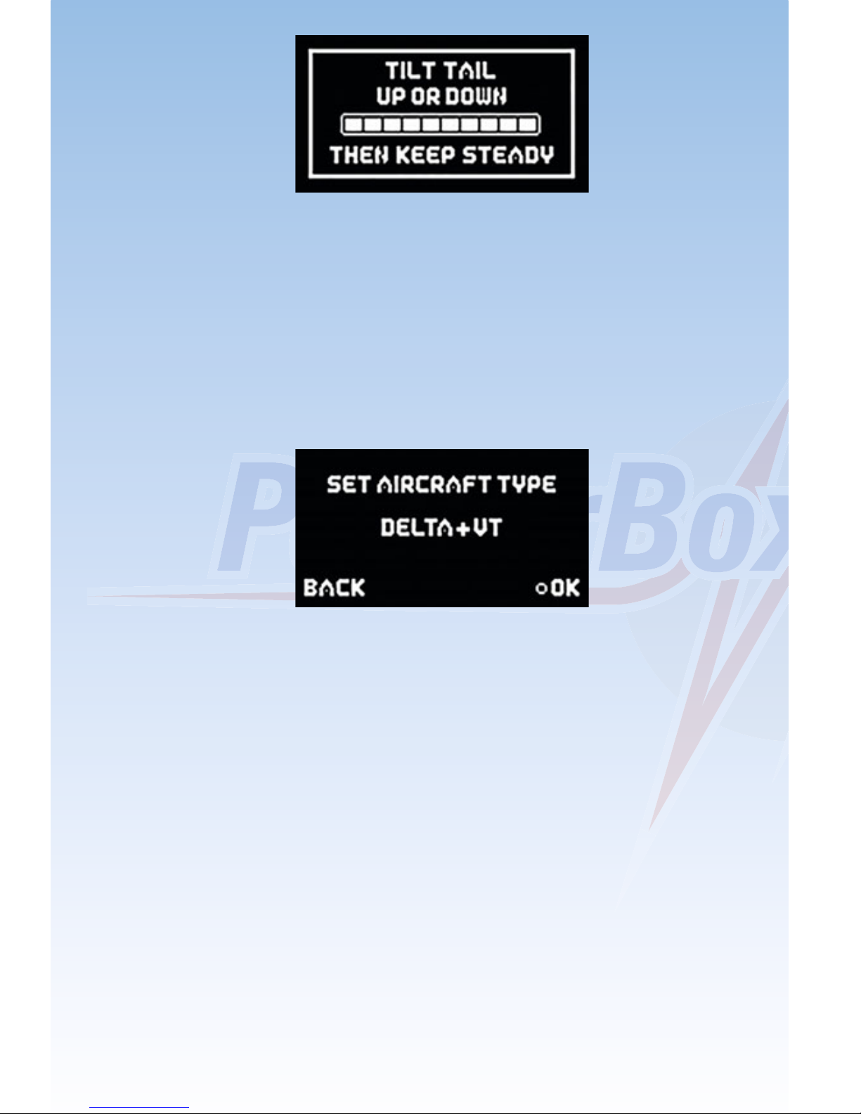
detect its installed orientation automatically. All you have to do is press the
model’s tail down (tricycle under-carriage) or lift it up (tail-dragger
undercarriage). You will see a bar display on the screen which reflects the
angle. You must lift the model to the point where the bar display is completely full to the right, then hold the model as motionless as possible. The
Mercury SRS now detects its installed position automatically.
-08-
You can install the Mercury SRS in any position, provided that the case is
at right-angles (90°) to the fuselage centreline.
4.2. Model type
The next step is to select the model type which is the closest match to your
aircraft. The main effect of your choice at this point is the assignment of the
outputs. Take a look at the table below and decide which output assignment suits your model best:
Note: it is also possible to change the output assignment at any time.
Explanation of terms:
DS 1 - 5: Door sequencer
VT: Vector thrust: thrust vector control
The two model types Normal+VT and Delta+VT include a special feature
as standard: in both cases the VT-RUDDER and VT-ELEVATOR outputs
are switched off in flight modes 1 and 2. This allows you to control a jet with
thrust vector control using only three channels, without having to set up
mixers at the transmitter. You only need to set up aileron, elevator and
rudder at the transmitter; thrust vector control is then switched on in flight
mode 3.
All outputs which are not assigned by the Assistant are marked “-”,
indicating that they are free for use with other functions.

-09-
-10-
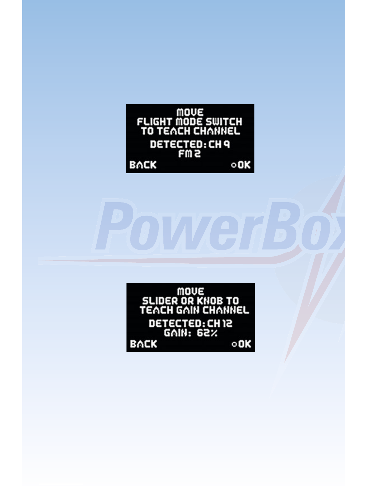
4.3. Flight mode switch
Assign a three-position switch of your choice at the transmitter, and check
that the travel is set to -100% to 0% to +100%. At a later point this switch
will be used to call up the gyro functions you have already set. Move the
switch once to all three positions in turn, and the channel will automatically
be detected. If the flight modes are not in the arrangement (direction) you
prefer, simply reverse that channel at the transmitter.
4.4. Gain channel
The gain channel is only required for the test-flight, during which the gyro
gain is adjusted to suit your model perfectly while it is in the air. Once the
set-up flight is complete, this function is disabled automatically. Assign a
rotary knob or slider to a vacant channel at the transmitter, and check that
its travel is set to -100% to +100%. Move the rotary knob or slider to both
end-points in turn, and the channel will be detected automatically.
-11-
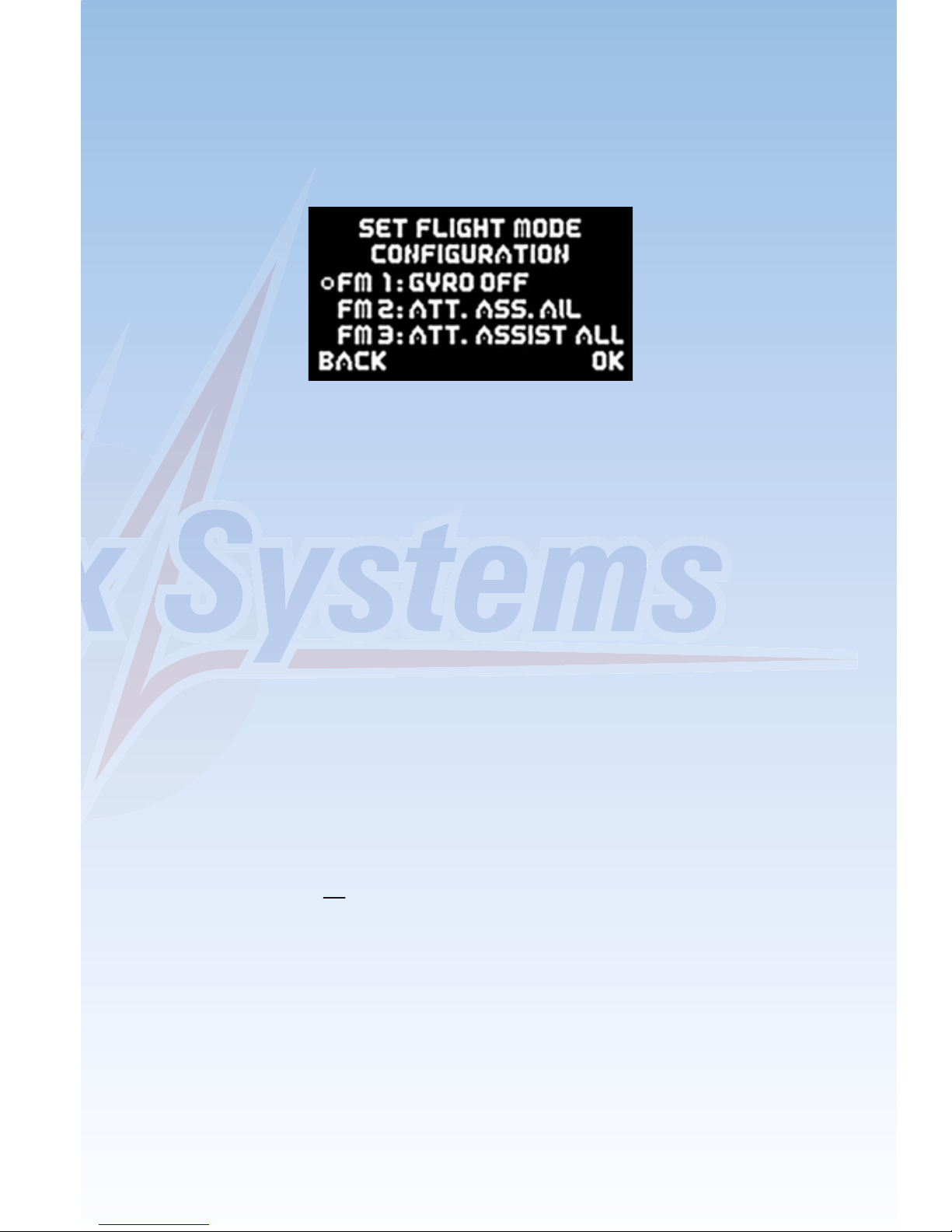
4.5. Flight mode configuration
The next stage is to define the gyro function required for each flight mode.
This setting defines the task which the iGyro is to carry out in flight modes
1, 2 and 3. Note that in flight mode 1 the Assistant only permits the
functions OFF or RATE MODE. The following options are available:
- OFF:
The iGyro is disabled.
- RATE MODE:
The iGyro operates in Normal mode on all control surfaces. The gyro
simply compensates for gusts of wind.
- ATT ASSIST STD:
Since the English terms “Heading mode” and “Hold mode” are not quite
applicable to the way the iGyro works, we have decided to adopt the
name “Attitude Assist Mode” for its unique control characteristics. If
the Attitude Assist Standard option is selected, the iGyro maintains
the model’s attitude, as last commanded by the pilot, around the roll and
pitch axes (aileron and elevator). At the same time the rudder operates
in Normal mode, so that turns can be flown in the usual manner. The
Attitude Assist Mode only operates at the neutral position of the sticks.
As soon as the pilot gives a command, the iGyro switches to Normal
mode. The result is 100% natural handling in the air. This function is
recommen ded for all models, and can be left active for take-off, flying
and landing. The control characteristics of the iGyro eliminate the need
to worry about stalling, which can occur with conventional gyro systems.
- ATT ASSIST ALL:
This setting is identical to the above option, except that attitude
maintenance is also active on rudder. This makes it easy to fly slow rolls,
as the rudder automatically maintains the correct attitude. However, this
flight mode option must not be used for normal flying, as the rudder
would then try to maintain heading through aileron turns, making the
model reluctant to turn.
 Loading...