

Page 1
Instruction Manual
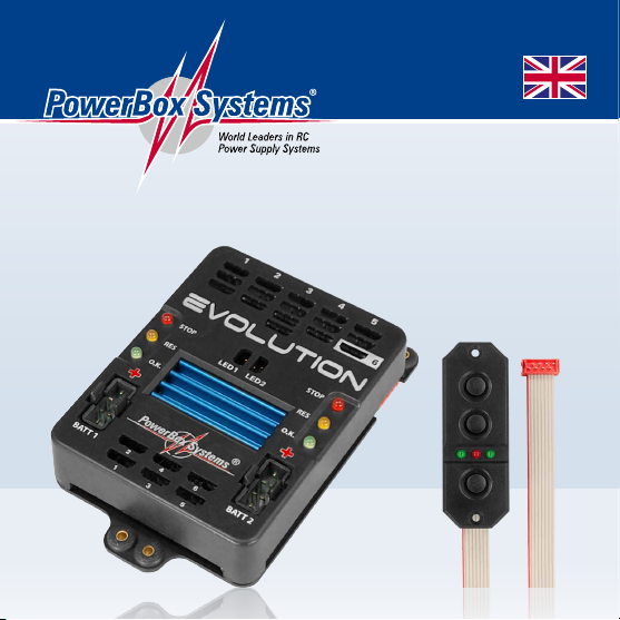
EVolution
Page 2

Dear customer,
We are delighted that you have decided to purchase the PowerBox Evolution from
our range.
We wish you every success with your new PowerBox Evolution, and hope you have
loads of fun with it.
1. PRODUCT DESCRIPTION
The PowerBox Evolution is a modern power supply system containing all the electronic components required to power modern receivers, servos and models. Every
single element, ICs, micro-controller and electronic circuit which is essential to a
reliable power supply is duplicated!
Features:
- Dual regulated output voltage
- Enlarged heat-sink area for even higher performance
- Signal amplication for a total of six channels
- Three voltage indicator LEDs
- Minimum value memory displays any voltage collapses which occur in-ight
- Support for four battery types: LiPo, LiIon, NiMH/NiCd, LiFe
- Suppression of any servo feedback currents which might occur
This range of functions makes the PowerBox Evolution the ideal battery backer
for large model aircraft with wingspans in the range 2.0 m to 2.6 m, as well as
helicopters and gliders.
2 PowerBox-Systems − World Leaders in RC Power Supply Systems
Page 3
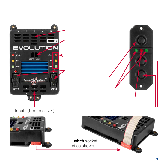
2. CONTROLS
The illustration below shows the essential control elements:
Servo Outputs
Sockets for external LEDs
Voltage indicator LEDs
Battery Sockets
SET button
LEDs for power-on status
LED for activation and battery type selection
Inputs (from receiver)
Switch button for batteries I and II
SensorSwitch socket
connect as shown:
www.powerbox-systems.com 3
Page 4

3. FIRST STEPS, THE UNIT IN USE
a) Connections
- First plug in all the servos to the desired channels. The channel assignment is
left up to you; for example, input 4 corresponds to output 4.
- Connect the receiver to the PowerBox Evolution using the six patch-leads sup-
plied in the set. Power is fed to the receiver via these leads.
- Now connect the SensorSwitch to the appropriate socket on the unit, ensuring
that the ribbon cable faces up as shown. In models subject to severe vibration
we recommend that you secure the ribbon lead by at least one additional point
to avoid the connector working loose. If the connector were to fall out, it would
have no effect on the switched state of the backer, but would prevent you switching the system off.
- The optional ultra-bright external LEDs can now be connected to the unit. We
urge you to connect them and mount them in the fuselage side, as they enable
you to detect battery problems when the model is ying.
- The nal step is to connect the batteries to the backer’s integral MPX connec-
tors. We recommend the use of batteries or 1500 mAh or 2800 mAh capacity
from PowerBox-Systems. If you prefer to use other makes of battery, or wish to
make up your own packs, it is absolutely essential to maintain correct polarity.
- Check twice rather than make a mistake! Connecting a battery with reversed
polarity will instantly ruin the backer’s regulators. In order to minimise power
losses, the backer does not feature reverse polarity protection. The + (positive)
indicator can be seen on the case cover.
4 PowerBox-Systems − World Leaders in RC Power Supply Systems
Page 5

b) The procedure for switching on and off
Switching the unit on and off is very simple, and the process effectively prevents
accidentally changing the backer’s status. This is the procedure:
Locate the SET button on the SensorSwitch and hold it pressed in until the central LED glows red. Now press buttons I and II in turn; the backer is now switched
on. Repeat the procedure to switch off: hold the SET button pressed in, wait until
the central LED glows red, then conrm by pressing buttons I and II in turn.
Once switched on, the backer can only be turned off again using the switch unit.
Intermittent contacts or interruptions in the power supply cannot cause the backer to be switched off permanently.
c) Setting the battery type
The default battery type setting is Lithium Polymer. If you wish to use two-cell
LiPo/LiIon packs, you therefore need to make no changes at this point. For all
other battery types adopt this procedure:
- Switch both batteries on.
- Hold the SET button pressed in, and watch the central LED on the SensorSwitch.
- The LED will light up, and then go out again after a brief period.
- After a few seconds the LED emits one brief red ash. If you now release the
button, you have selected the battery type LiPo/LiIon.
- If you allow the LED to ash twice before releasing the button, you have selected ve-cell NiCd/NiMH as the battery type.
- If you hold the button pressed in until the LED has ashed three times, the vol-
tage indicator is prepared for LiFe (A123) packs.
www.powerbox-systems.com 5
Page 6

This process only takes a few seconds, and is designed to eliminate the danger of accidental changes to the setting. In any case it only has to be carried
out once, as your selected battery type is permanently stored in the backer’s
EEProm.
d) Reading out the minimum value memory
The minimum value memory shows you the extent to which the battery voltage
collapsed during the last ight. Control surfaces with a tendency to jam, stiff
linkages, or simply batteries which fade under load, may be the cause of any problem in this respect. Please make it part of your routine to read out this minimum
value memory after every ight, as this enables you to detect any weakness in
the system before the next ight.
The method of calling up the memory is simple:
After the ight, press both switch buttons Battery I and Battery II simultaneously,
and hold them pressed in as long as you like. The LED which now lights up in-
dicates the lowest voltage value which occurred during the ight. The memory
does not record voltage collapses which were of very short duration; only those
lasting longer than one second.
e) Changing the output voltage 5.9 V / 7.4 V
You can set your PowerBox Evolution to either of two different output voltages.
The default stabilised voltage is 5.9 Volts. If you wish to raise the voltage to 7.4
Volts, please check carefully that all the components in your model are designed
and approved for the higher voltage.
6 PowerBox-Systems − World Leaders in RC Power Supply Systems
Page 7

In 7.4 Volt mode the dissipated power is lower, and this means that the power of
your PowerBox Evolution is about 30% higher.
By default both voltage regulators are set to 5.9 V. If you wish to use high-voltage
servos (HV servos, designed for up to 8.4 V), the PowerBox Evolution allows
you to operate the servos on a regulated voltage of 7.4 V instead of 5.9 V. The
advantage of a regulated 7.4 V voltage compared with an ‘open’ 8.4 V battery
is that the regulated voltage causes all servos to work constantly at the same
speed and generate the same torque. This is an important advantage which is
particularly appreciated by all our competition pilots, as it makes all manoeuvres
more predictable and easier to y.
A further advantage of a regulated 7.4 V servo voltage is a longer effective life for
your servos, as it eliminates the voltage peaks which occur when the batteries
are freshly charged.
Setting the servo voltage:
The procedure for switching the unit to 7.4 Volts is quick and simple, and only
needs to be carried out once. The setting is stored permanently, but can also be
changed again at any time. The change must be carried out for each of the two
voltage regulators, as the PowerBox Evolution features two regulators which
work independently of each other.
www.powerbox-systems.com 7
Page 8

To change the output voltage, connect both batteries and switch the PowerBox
Evolution on.
Now disconnect both batteries from the PowerBox Evolution.
Press the SET button and hold it pressed in. With the SET button pressed in,
reconnect Battery 1 and Battery 2.
The selected setting is indicated by the LED monitor on the PowerBox Evolution:
all the LEDs on the appropriate side light up:
1 x ash means that the regulator is now operating at 5.9 V
3 x ashes means that the regulator is now operating at 7.4 V
The output voltage is switched by a toggle process. Example: the set voltage
is 5.9V; if you connect the batteries with the SET button pressed in, the output
voltage changes to 7.4 V, and the LEDs ash three times. If you wish to revert to
5.9 V, you must disconnect the batteries and repeat the procedure.
Caution: it is essential that both regulators are set to the same voltage. If you
set only one regulator to 7.4 V, the voltage at the output is 7.4 V.
8 PowerBox-Systems − World Leaders in RC Power Supply Systems
Page 9

4. SPECIFICATION
Operating voltage: 4.0 Volt to 9.0 Volt
Power supply: 2 x 5-cell NiCd or NiMH batteries,
2 x 2-cell LiFe batteries (A123)
2 x 2-cell LiPo/LiIon batteries, 7.4 Volt
Current drain: Switched on: approx. 80 mA
Switched off: approx. 4 µA
Dropout voltage: approx. 0.25 V
Max. receiver/servo voltage: 2 x 10 A (stabilised), according to cooling measures
Peak 2 x 20 A
Servo sockets: 16 sockets, 6 channels
Temperature range: -30°C to +75°C
Dimensions: 93 x 67 x 19 mm (incl. base plate)
Weight: 86 g
Sensor-Switch: 15 g
EMV approval: EN 55014-1:2006
CE approval: 2004/108/EG
WEEE Reg. No.: DE 639 766 11
Registered design: DE 203 13 420.6
This battery backer fulls the EMV protective requirements, EN 55014-1:2006
with certicate dated 10th February 2009. EMC approval 2004/108/EG.
The unit must not be connected to a mains PSU!
www.powerbox-systems.com 9
Page 10

5. DIMENSIONS
6. SET CONTENTS
- PowerBox Evolution
- SensorSwitch
- 6 patch leads
- 2 external LEDs
- 4 rubber grommets and brass spacers
- 4 retaining screws
- Operating instructions
10 PowerBox-Systems − World Leaders in RC Power Supply Systems
Page 11

7. SERVICE NOTE
We are anxious to offer good service to our customers, and to this end we have
set up a Support Forum which deals with all queries concerning our products. This
relieves us of a great deal of work, as it eliminates the need to answer frequently
asked questions time and again. At the same it gives you the opportunity to obtain
help quickly all round the clock – even at weekends. All the answers are provided by
the PowerBox Team, guaranteeing that the information is correct.
Please use the Support Forum before you telephone us.
You can nd the forum at the following address:
www.forum.powerbox-systems.com
www.powerbox-systems.com 11
Page 12

8. GUARANTEE CONDITIONS
At PowerBox-Systems we insist on the highest possible quality standards in the
development and manufacture of our products. They are guaranteed “Made in
Germany”!
That is why we are able to grant a 24 month guarantee on our PowerBox Evolution
from the initial date of purchase. The guarantee covers proven material faults,
which will be corrected by us at no charge to you. As a precautionary measure, we
are obliged to point out that we reserve the right to replace the unit if we deem the
repair to be economically unviable.
Repairs which our Service department carries out for you do not extend the original
guarantee period.
The guarantee does not cover damage caused by incorrect usage, e.g. reverse
polarity, excessive vibration, excessive voltage, damp, fuel, and short-circuits. The
same applies to defects due to severe wear.
We accept no liability for transit damage or loss of your shipment. If you wish to
make a claim under guarantee, please send
the device to the following address, together
SERVICE ADDRESS
with proof of purchase and a description of
the defect:
PowerBox-Systems GmbH
Ludwig-Auer-Straße 5
D-86609 Donauwoerth
Germany
12 PowerBox-Systems − World Leaders in RC Power Supply Systems
Page 13

9. LIABILITY EXCLUSION
We are not in a position to ensure that you observe our instructions regarding installation of the PowerBox Evolution, full the recommended conditions when using
the backer, or maintain the entire radio control system competently.
For this reason we deny liability for loss, damage or costs which arise due to the
use or operation of the PowerBox Evolution or which are connected with such
use in any way. Regardless of the legal arguments employed, our obligation to pay
compensation is limited to the invoice total of our products which were involved in
the event, insofar as this is deemed legally permissible.
We wish you every success using your new PowerBox Evolution!
Donauwoerth, January 2021
www.powerbox-systems.com 13
Page 14

01/2021
PowerBox-Systems GmbH
Ludwig-Auer-Straße 5
D-86609 Donauwoerth
Germany
+49-906-99 99 9-200
+49-906-99 99 9-209
www.powerbox-systems.com
 Loading...