

Instruction Manual
PREVIEW

2
PowerBox-Systems − World Leaders in RC Power Supply Systems
Dear PowerBox pilot,
Many thanks for placing your trust in us, and purchasing our PowerBox CORE. You have chosen an extremely
unusual radio control system: the CORE has great presence and allure, which you cannot fail to appreciate when
you pick up the transmitter for the rst time. The CORE ts perfectly in your hands, and is the perfect tool for
controlling your valuable models with precision.
30 months have passed between the initial idea and the start of series production: in this time we have developed
everything from the ground up: electronics, mechanical systems, choice of components and suppliers, external
appearance, technical design, mould construction, software architecture, basic operating philosophy and endless details.
Development started late, and the system had to be completely re-designed, but over time we realised that this
offered one great advantage: compatibility with old systems developed in the past did not have to be considered
in any way. This is a very important benet, since there have been signicant technical advances in the eld of
2.4 GHz systems since the start of the current era.
A single example will sufce to underline this advantage: the highly developed radio link, offering a range of
more than 9 km. This is unique, and provides unrivalled system reserves. Further advances are evident in our
new bi-directional P²BUS which operates as the telemetry interface, and is capable of transferring data at un-
precedented speed. The most important advance as far as the pilot is concerned is the user interface, which is
controlled using the transmitter’s integral touch-screen: the entire menu system is accessed from here, and the
self-explanatory menus are completely logical in their structure. The internal high-performance Linux computer
provides unlimited future expansion potential.
We are condent that we can guarantee our customers durability and quality at the very highest level, because
we exclusively use components of the highest possible industrial quality, produced by top manufacturers.
The entire production process - starting with circuit board assembly and extending right through to nal as-
sembly in our own premises - takes place in Germany. Each CORE is hand-made, and represents an example of
German craftsmanship at its best! All our staff are united in their shared aim: perfection!
We wish you many hours of pleasure and countless successful ights with your new PowerBox CORE!
CONTENTS
1. Connections, controlls ................................................ 3
2. Initial steps .................................................................... 4
3. Function menu .............................................................. 8
4. Binding a receiver ....................................................... 11
5. Mixer ............................................................................. 12
6. Telemetry ..................................................................... 13
7. Charging the transmitter ...........................................14
8. Connections ................................................................ 15
9. Mechanical transmitter adjustments ..................... 15
10. Calibrating the transmitter controls .....................18
11. Specication ............................................................. 18
12. Set contents .............................................................. 18
13. Service Note ..............................................................19
14. Guarantee conditions .............................................. 19
15. Liability exclusion ..................................................... 19
www.powerbox-systems.com
3
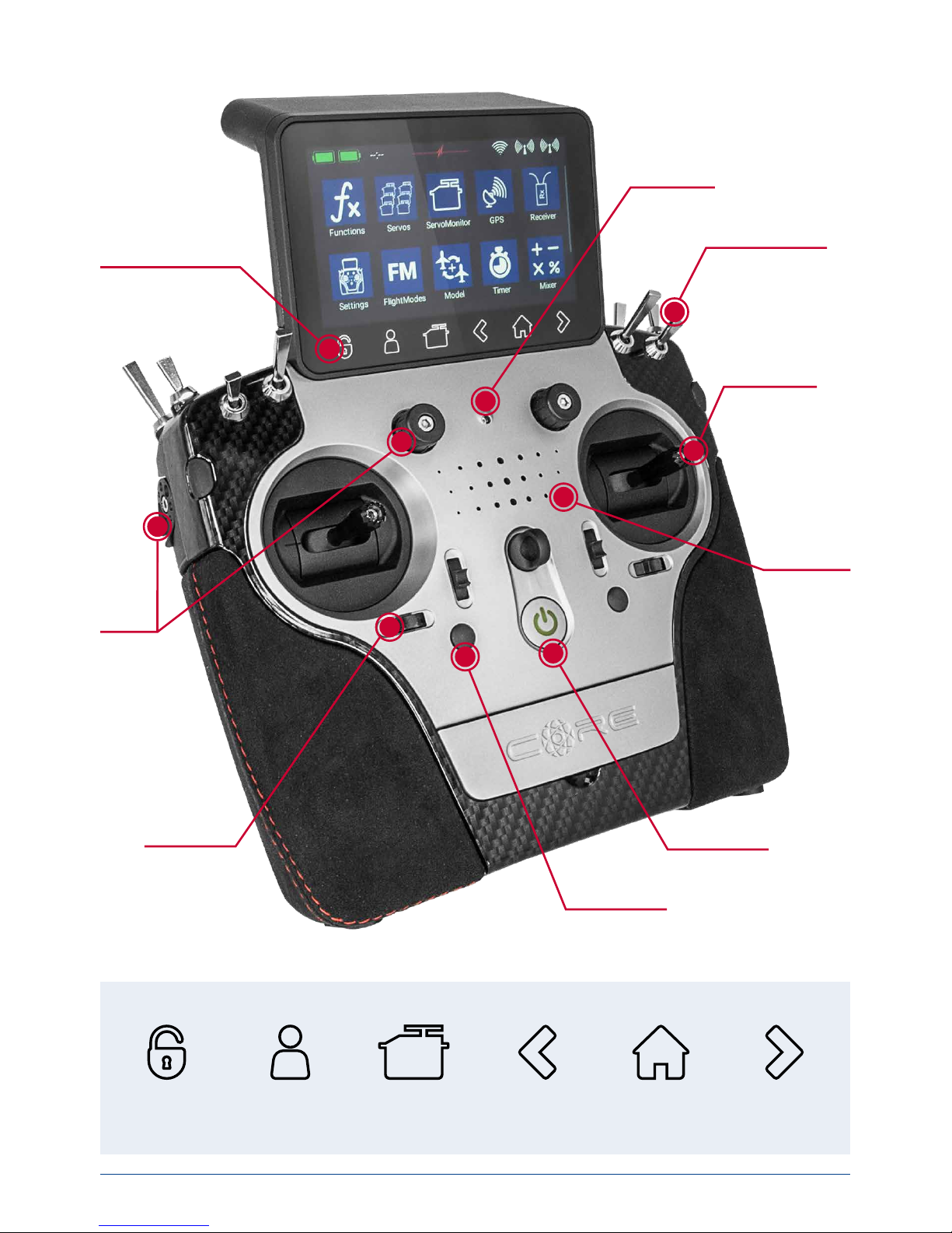
Quick-select buttons
1. CONNECTIONS, CONTROLLS
8 Toggle switches
Light sensor
Quick-select buttons
Optional stick
switch
Loudspeaker
4 digital trims
4 proportional
controls
On / Off switch
4 push-buttons
Screen
unlock
User-
dened
menu
Servo
monitor
History
back
Home screen History
forward
4
PowerBox-Systems − World Leaders in RC Power Supply Systems
2. INITIAL STEPS
a) Switching on
The CORE is switched on by holding the
-button pressed in until it lights up red. Release the button briey, then
conrm the power-on process by briey pressing the button a second time. The transmitter is switched off in
exactly the same way. The button changes to green when the Linux system has booted; this process takes about
25 seconds.
Once the CORE is running, you will see the Home display on the screen: this shows elds containing telemetry
values, timers, servo positions or quick-select buttons for menus. These elds are known as widgets.
Note: the CORE is tted with a fully redundant power supply system, which is deliberately kept separate from
the Linux computer and the other processors. This means than any malfunctions in the complex Linux system cannot possibly result in the transmitter switching itself off. The two real-time processors also function
completely independently of the Linux computer.
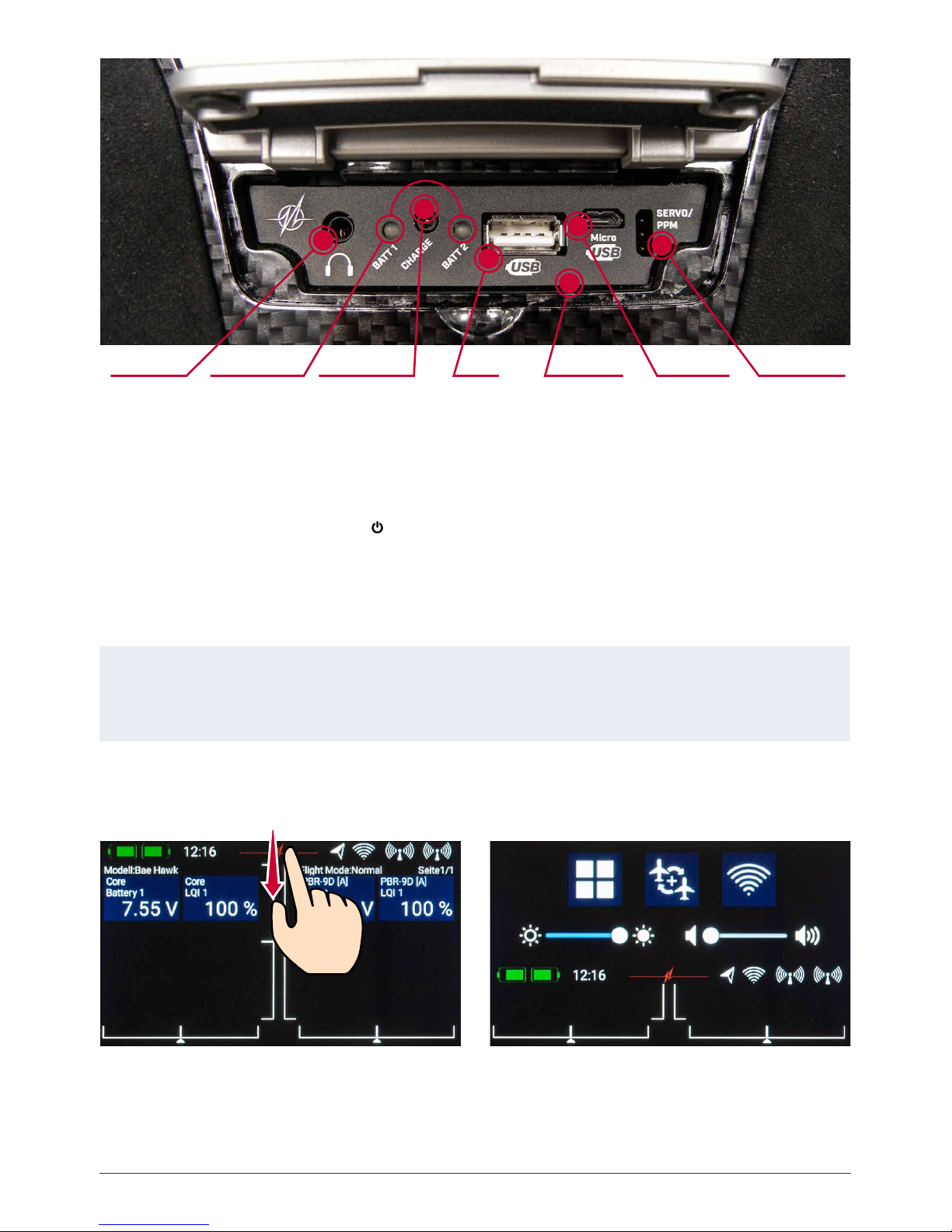
b) Entering the menu
The main menu is accessed by swiping a nger downwards from the top edge. You can now touch the left-hand
menu symbol:
There is no need to press rmly, as the capacitive touch-screen simply responds to touch, like all modern smartphones.
The symbols in the Main menu are arranged in order of importance.
Headphone
socket
Charge status
LED
Charge socket
(10-16V)
USB-A
socket
Microphone
input
Micro USB
socket
Servo tester/
PPM output
www.powerbox-systems.com
5
Note: you can transfer any menu point to your own personal menu. This is accomplished simply by holding
your nger on the appropriate menu for a few seconds. When the “Person symbol” appears, the menu point is
transferred into your personal menu, which you can access conveniently using the quick-select button at the
bottom of the screen. If you wish to remove a menu point again, use the same procedure: keep your nger on
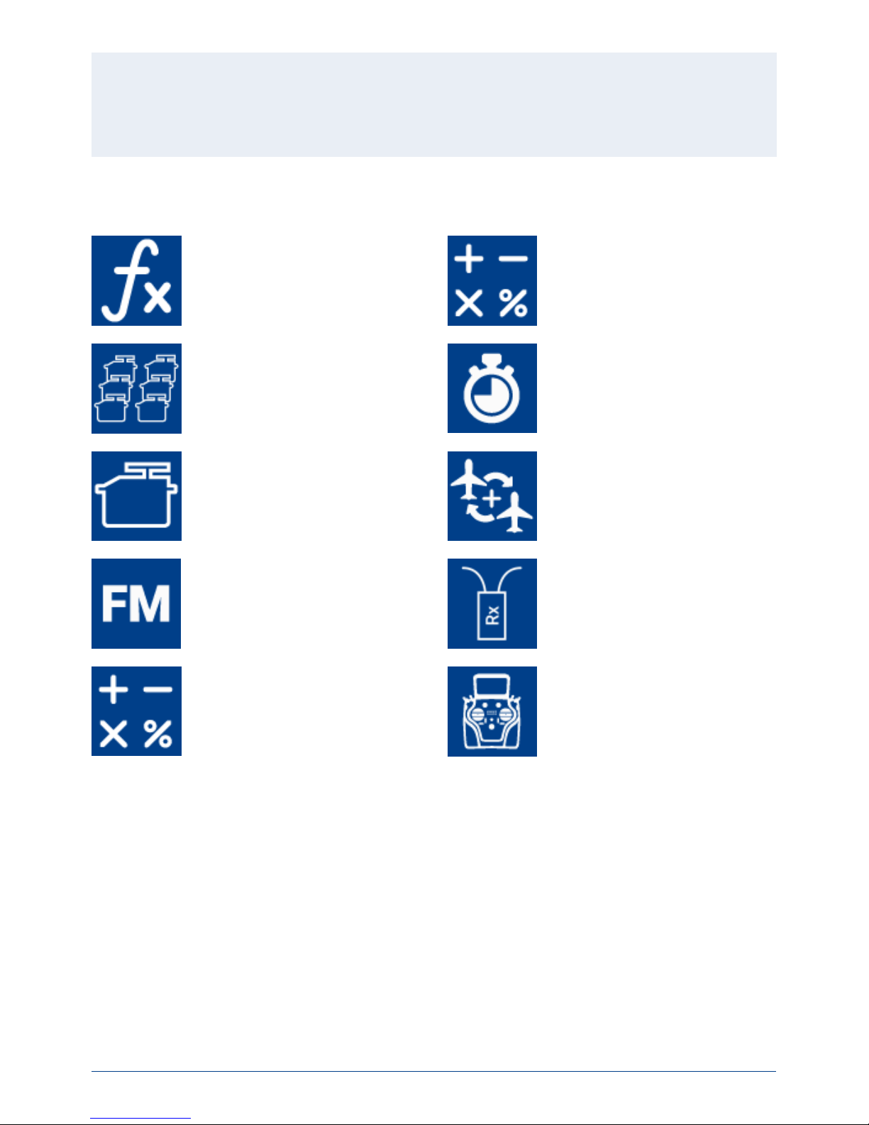
the menu symbol in question, and that entry is duly erased.
Functions
- Function overview
- Create or erase functions
Menu
Mixers
Servos
- Servo overview
- Create or erase functions
Timers
Servo monitor Model
- Model overview
- Load, copy or erase models
Flight modes Receiver
- Receiver overview
- Bind or remove receiver
- Range check
Virtual switches Settings
- System
- Screen
- Audio

6
PowerBox-Systems − World Leaders in RC Power Supply Systems
The Dimmer time setting determines the point at which the screen is automatically darkened. The automatic
screen lock can be released again using the
-button (quick-select button, bottom left).
d) Creating a model
Select the Model button in the Main menu, and you will see an overview of all models stored in the transmitter.
c) Settings
This menu point is used to set your personal preferences.
The System sub-menu is used to enter your name, set the time display format, select your preferred language,
display the software version and update the software when necessary. Another important point is the Calibration
menu; this is described in full at a later stage.
In the Screen sub-menu you can select the background colour and icon colour. The brightness control should be
set to a value which enables you to see the screen content clearly and distinctly.
Note: the ultra-bright TFT screen allows you to see everything clearly even in bright sunshine. However, the
screen brightness does have a perceptible effect on battery duration!

www.powerbox-systems.com
7
If you now leave the Select screen again, you will see
that the same transmitter control has also been assigned automatically to the right aileron.
The next step is to select the servo outputs to which you
intend to connect the aileron servos; this is accomplished by pressing +. Note that you can assign up to eight
servos to a single function.
If your model is an aerobatic aircraft, you would naturally select two or three servos at this point. At a later stage
you will be able to set the travel, direction of rotation and centre position for each servo separately.
If these parameters are too coarse for your application, you can set an individual curve with up to 33 points for
each servo.
Back in the Assignment screen it is also possible to rename the functions to suit your own preference.
If you decide to assign the wing aps at this point, you will learn to appreciate one of the truly unique features of
To create a new model, briey touch the + button at the
bottom of the screen. Assign a name to your model,
and conrm your choice with OK. You will now see the
Select screen for the model type.
At this point you can select the appropriate model type,
with the additional options of delta wing and V-tail.
On the next screen you select one of the ranges on the
right-hand side, e.g. Wing. The screen now shows a diagram of a wing corresponding to your chosen type. If
your conguration is more specialised, that presents no
problems: at a later stage you can very easily program
individual functions manually.
Here you will see the name of the function (e.g. Aileron
L), a transmitter control and a + symbol, which is used
to assign the appropriate number of servos. These individual Select points are inter-connected; the method
used for this will become self-evident in the course of
the set-up procedure.
Now you select a transmitter control which is to control
the left aileron; this will be the left or right primary stick,
depending on the transmitter mode you prefer.
Note: the software of the CORE has no modes – it
is only the mechanical settings of the transmitter
sticks which determines the stick mode.

8
PowerBox-Systems − World Leaders in RC Power Supply Systems
the CORE. As with the ailerons, you again assign a transmitter control to the aps. If each ap is operated by a
separate servo, you won’t notice anything unusual: you simply assign the aps to your preferred servo outputs.
However, if you also want the ailerons to double as aps, or want the ailerons to be mixed in to the aps, you
also assign the aileron outputs to the ap function. These functions are now superimposed, i.e. the mixing is
accomplished simply by assigning the servos.
At a later stage you can adjust the servos individually, both for the Aileron function and the Flap function. Servo
travel, centre and direction can be set separately for both functions!
An even clearer example of this exceptional feature relates to models with a delta wing. If you select a delta using
the Assistant, the correct functions are assigned automatically. To clarify this, the manual method would be as
follows:
As an example servos 1 and 5 are assigned to Aileron. Servos 1 and 5 are also assigned to Elevator. Since the
servos are installed in a mirror-image arrangement, it is logical that the servos always operate as ailerons, regardless of whether the pilot moves the elevator stick or the aileron stick. Now we switch to the Elevator function
and reverse the direction of rotation of one servo. The elevator function now works correctly, but the “reversed”
elevator function has no effect on the servo direction when an aileron command is applied, i.e. the ailerons still
work correctly. That’s all there is to setting up a “delta mixer”.
Back to our Wing screen: when all the assignments are complete, press the
-button amongst the quick-select
buttons at the bottom in order to return to the overview.
You can now continue assigning transmitter controls and servos to all the remaining functions. When everything
is nished, touch Continue at bottom right. The functions and servo assignments are complete.
3. FUNCTION MENU
You now arrive at the most important screen display:
the Function Overview. In principle, the set-up of the
whole model is carried out from this starting point. The
display is arranged logically from left to right:
Function Transmitter control Trim Setup
Failsafe Servo(s)
The individual points in detail:
A. Function
Each function always contains a transmitter control, the associated trim, the settings for the transmitter control
- such as Expo and Travel, Failsafe or Hold - and the assigned servos.
Each function can also be renamed just as you wish at this screen: simply touch the Function name.
B. Transmitter control
At this point you can assign a transmitter control or a
xed value to the function. A transmitter control may
be a primary stick, a proportional control, a switch or a
push-button.

www.powerbox-systems.com
9
C. Trim
a) Trim control
It is necessary to assign a trim control as the rst step
here. This can be one of the four trims located adja-
cent to the primary sticks, or two of the four rubberised
push-buttons. If you select the push-buttons, the buttons always work together left and right as the trim.
b) Trim mode
You can choose any of four different trim modes. The
standard one is Centre mode: in this mode any change to the trim only affects the central range, i.e. not the
end-points.
Alternative trim modes are Left and Right; typically these are intended for idle adjustment in the case of engines
and turbines.
The option of Offset trim mode also affects the end-points when the trims are adjusted.
c) Min./Max.
This menu point can be used to limit the permissible trim range. The percentage value determines the maximum
or minimum travel over which the trim is allowed to move.
d) Steps
Here you can set the number of trim steps or increments; not the size of the step.
Note: if you change the Min. / Max. values but leave the number of steps the same, the step size changes
accordingly.
D. Setup
At this point you can adjust the transmitter control input, Expo, transit time and curves.
a) Transmitter control rate
Here you can select a transmitter control which switches the rate on and off, or sets it to linear. The transmitter control can be any of the primary sticks, proportional
controls or switches.
b) Rate
The purpose of the Rate button is to adjust the travel of the transmitter control. If you select nothing for Trans-
mitter control rate, the value is xed. If you assign a transmitter control to Transmitter control rate, you can set
different values on three levels. The level initially selected with the transmitter control you have selected is shown
in green. If you select a proportional control as transmitter control, the values are applied in a linear fashion within
the three levels.
c) Transmitter control expo
At this point you can select a transmitter control which is used to switch an Expo characteristic, or set it to linear.
You can choose any transmitter control from the primary sticks, proportional controls or switches.
d) Expo
The purpose of the Expo button is to adjust the exponential factor. If you select nothing for Transmitter control
expo, the value is xed. If you assign a transmitter control to Transmitter control expo, you can use it to set diffe-
rent values on three levels. The level initially selected using the transmitter control you have selected is shown in
green. If you select a proportional control as transmitter control, the values are applied in a linear fashion within
the three levels.

10
PowerBox-Systems − World Leaders in RC Power Supply Systems
e) Curve editor
The curve editor is used to set up special curves.
- The rst step is to select the number of points: up to
33 can be specied.
- Use the arrow buttons to select the point which you
wish to move; the selected point changes colour to
green.
- Adjust the percentage value to shift the point up or
down.
- The Smooth option can be used to even out the curve,
and thereby avoid jerks in the servo’s response.
- Raw removes the effect of the curve smoothing.
- Reset curve resets the curve to linear travel.
f) Transit time
At this point you can set two transit times: one determines the servo transit time to the left, the other to the right.
The time in seconds determines how long the servo takes to move from one end-point to the other.
E. Hold /Failsafe
If you want a servo to take up a pre-determined position
in case of radio signal loss, you should select Failsafe
here. The Learn button now appears, enabling you to
store the current position in the receiver.
Note: the receiver or receivers do not need to be
bound at this point. The Failsafe positions are repeatedly transmitted to the receiving system.
F. Servo
Here you will nd the assigned servos again. Up to eight
servos can be assigned to each function. As already
mentioned in the Assistant, the travel and end-points
of each servo can be adjusted separately here. Any
adjustments you make to a servo at this point have no
inuence on the settings of the same servo if it is also
assigned to another function. This provides a simple
means of mixing in aircraft with multi-ap wings, delta
wings and V-tails.
- Servo number: indicates the receiver output at which this servo signal is present.
- Servo name: the servo name can be changed individually. Hold your nger on it to open up the keypad.
- Limit: works like a mechanical stop – the servo does not move beyond the set point.
- Travel: adjusts the servo travel.
- Centre: offsets the servo centre position. Acts like a “mechanical” centre offset – it also affects the end-points.
- Direction: reverses the direction of rotation of the servo.
- Curve editor: each servo can be adjusted very precisely to match the model’s mechanical arrangement by
means of a curve consisting of up to 33 points.

www.powerbox-systems.com
11
If you wish to adjust a servo’s travel or centre position, the rst step is to touch the appropriate button; you can
now adjust the value. As soon as you move the associated stick, the Select button shifts to the corresponding
position. This means that you do not need to select Left, Right and Centre when adjusting the control surface;
instead you select each point very conveniently using the transmitter stick, altering the position of the control
surface using the arrow buttons at the bottom of the screen. At the same time you can observe the effect of any
change directly on the servo.
4. BINDING A RECEIVER
Select the Receiver button from the Main menu. As you
will now see, up to four receivers can be bound to the
CORE simultaneously.
It is even possible to use different types of receiver; for
example, one PBR-9D and one PBR-5S can be bound.
All four receivers are of “equal value”, i.e. there is no
Master / Slave assignment, and no restrictions in terms
of telemetry. Telemetry sensors can be connected to all
four receivers, all of which send data to the CORE on an
equal footing.
The receivers are identied by the four capital letters A to D. The same letters appear in the telemetry data sent
from the receivers, helping to differentiate between them.
a) Binding
There are two methods of binding receivers:
1. Connect a power supply to the receiver, and it will respond by ashing green at high frequency for ten seconds.
Press the Bind button on your CORE transmitter, and the receiver now binds to it; the LED lights a continuous
green.
If you do not press the Bind button within the ten-second period, the LED switches to ashing slowly red – at
this point the receiver can no longer be bound to the transmitter. You can only re-start the process if you rst
disconnect the power supply.
2. Press the Bind button on your CORE, then connect the receiver to a power supply. The LED switches to conti-
nuous green once the receiver is bound.
Technical information: during the binding procedure the PowerBox CORE generates a random sequence
from a total of more than 32 million numbers; this is then used as the basis for calculating the hopping sequence and encoding the signal. The likelihood that two identical codes could be generated is therefore very
close to zero.
b) Remove
The Remove button has an important function: if you wish to uninstall a receiver from a model, it is essential to
remove that receiver from the model memory beforehand using this button. If you simply uninstall the receiver
without rst removing it at the transmitter, then the other bound receivers will not work when you next switch the
system on. This is an important safety feature, as it ensures that all the bound receivers are working when you
switch the system on, i.e. before you take off!
c) Range check
The range check function reduces the transmitter’s output power, thereby simulating a large distance between
transmitter and model. This enables you to determine any possible weaknesses in reception in the receivers.
In range check mode all the controls should work perfectly at a range of at least 50m. The range check switches
itself off automatically after 120 seconds.

12
PowerBox-Systems − World Leaders in RC Power Supply Systems
5. MIXER
The free servo mixers represent an additional method
of mixing functions with each other. Servo mixing by
servo assignment has already been described in the
Function menu, but this option also enables you to mix
functions with each other with a response curve.
You can create a new mixer by selecting the Mixer menu
and pressing +. You can also immediately rename the
Mixer to your own choice by touching the Mixer button.
Press the Setup button on the right in order to program
the mixer. The following display appears:
• From / To
The rst step is to select the source function under
From, and the target function under To .
• Transmitter control
At this point you should select a switch, stick or proportional control. You can then use it to activate the mixer,
switch the input to the three available levels (1-2-3), or
set it to linear response. The default entry here is On, which means that a xed mixer input is set.
• Input
The Input button is used to set the magnitude of the mixer. Selecting On at Transmitter control sets a xed value.
If you assign a switch or proportional control at Transmitter control, you can set different values on three levels;
the level selected by the transmitter control is shown in green. If you select a proportional control as transmitter
control, the values are applied in a linear fashion between the three levels.
• Curve editor
The curve editor enables you to set up special mixing curves.
- The rst step is to select the number of points: up to 33
points can be specied.
- Use the arrow buttons to select the point which you
wish to move; the selected point changes colour to
green.
- Adjust the percentage value to shift the point up or
down.
- The Smooth option can be used to even out the curve,
and thereby avoid jerks in the servo’s response.
- Raw removes the effect of the curve smoothing.
- Reset curve resets the curve to linear travel.

www.powerbox-systems.com
13
6. TELEMETRY
Once you have created a new model and bound one or
more receivers, you can display important information
on the main screen using the telemetry widgets.
To create a widget, touch an empty area of the main
screen, and you will see the following display:
You will now see twelve grey elds, together with a P+ button and a P- button. The P+ button can be used to
create additional pages, so that more telemetry widgets can be displayed. You can move to and fro between the
pages by swiping with your nger. The P- button is used to erase empty pages.
Touch one of the grey elds, and this screen display
appears:
You can select any of four different types of widget:
- Telemetry
- Servo values
- Timer
- Quick-select menu
Telemetry
This can be used to display all the sensors connected to
the P²BUS, and show the data they generate. This infor-
mation also includes the receiver and transmitter data.
If you select the Telemetry widget type, this screen display appears:
The left-hand column shows all the connected sensors, while the right-hand column shows all the values
which these sensors supply. The P²BUS is an in-house
development, and is capable of transmitting up to 255
sensors each with 32 individual values – and at a speed
of up to 800 values per second!
It is possible to set up each widget to display multip-
le sensor values, even from different sensors; these
values are then displayed in turn by the widget. This is
accomplished by selecting one or more sensor values
which you want your widget to display, then conrming
your choice with OK.
A list of the selected sensor values is displayed. You
can use the + button to select additional values from
another sensor.
At this screen display you can adjust the size of the widget using the Small, Medium and Large buttons. The
Erase widget function can be found at bottom left.

14
PowerBox-Systems − World Leaders in RC Power Supply Systems
The Rescan sensors button is required if you wish to connect new sensors while the system is operating.
Touching the button forces the system to re-collect all sensor information on the P²BUS. In principle, all sensor
information is collected automatically every time the system is switched on.
Technical information: the PowerBox CORE telemetry system and the P²BUS are designed in such a way
that each sensor supplies its own information, including sensor name, unit, number of sensor values, decimal
point, priority and other data. A new sensor designed for use with the P²BUS can be connected to the system
at any time without updating the transmitter.
The advantage of the system is that all the text information relating to the sensor values is collected only
when the system is switched on, i.e. when the system is booting.
Once the system is running, only the pure sensor values are transferred; this permits very fast data transmission with maximum exibility, and ensures a thoroughly user-friendly system.
Behind the individual sensor values you will nd the Alarm button. The Alarm menu allows you to set four alarm
thresholds: one yellow alarm and one red alarm for each direction. This enables you to select different thresholds
coupled to different sounds, text, or vibration modes.
For example, you might set up battery capacity alarms for an electric model: a yellow audible alarm when there
is just sufcient energy remaining for one minute of ight; a red audible alarm with vibration for twenty seconds.
Touching the Back button returns you to the Sensor overview. Press OK at the bottom when you have completed
all the settings.
The widget now appears in the location where you started, but widgets can also be placed in any position. This
is accomplished by holding your nger on the screen until the widgets start to icker; you can now move the
widgets around on the screen. To x the widgets in position again, simply wait a few seconds or press the Home
button.
Servo values, Timers, Quick-select menu
Widgets can also be set up for individual servo outputs, timers or menu entries, in exactly the same way as de-
scribed for telemetry values. The procedure is identical: hold your nger on a vacant space in the main screen,
then make your selection as already described.
7. CHARGING THE TRANSMITTER
If you wish to charge the CORE, the rst step is to open the front cover. Locate the two plugs attached to the
mains PSU, and insert either one into the charge socket. If the battery symbol is displayed large and ashing on
the screen, this means that you have a reserve for about 20 - 30 minutes. You must charge your CORE at this
point, if not sooner. For safety reasons the CORE does not feature a battery cut-off. Never allow the transmitter
to become deep-discharged!
The LEDs light up red when the batteries are on charge, and green when the charge process is complete. The
charger can be left connected to the CORE after charging without causing damage, as the internal charge control
circuits regulate the charge process completely automatically.
The battery charge process takes about 3.5 hours from the fully discharged state.
The CORE can also be recharged while it is switched on, e.g. for protracted programming work.
Note: in addition to the bar display at top left on the screen, you can also set up the transmitter to display
its own exact battery voltage on the main screen in the form of a telemetry widget, and set a corresponding
alarm. The transmitter is tted with two internal 7.2V Li-Ion batteries of 3400 mAh capacity. Sensible alarm
values would be 6.8V for an orange alarm, and 6.6V for a red alarm.
Note: the mains PSU is the same type used for PowerBox Batteries and PowerPaks, and can also be used
to recharge these batteries.

www.powerbox-systems.com
15
Caution: if you clean the handrests, it is essential to allow them to dry out completely before re-attaching
them to the transmitter, otherwise damp could enter the transmitter and cause corrosion damage!
Note: In the initial production run these functions are not yet implemented in full!
8. CONNECTIONS
Under the front cover you will nd additional sockets (see illustration on page 4):
- Headphone socket: stereo headphones can be plugged in here for spoken vario or telemetry messages.
- USB-A socket: this accepts a USB stick, which can be used to update the radio control system. Data from the
CORE can also be copied onto the USB stick.
- Micro USB socket: for direct exchange of data with a PC.
- Servo/PPM: servos plugged into this socket respond directly to the movements of the primary sticks. This can
be extremely useful for centring servos accurately before installation, or for subjecting them to a brief function
test. This output is protected with a 1A fuse, and is therefore not suitable for load-testing servos!
It is also possible to switch this socket to PPM output for use with ight simulators or Trainer (buddy-box) sys-
tems.
9. MECHANICAL TRANSMITTER ADJUSTMENTS
a) Removing the handrests
The handrests tted to the CORE can be removed quickly and easily: simply undo the four socket-head screws in
the feet, and the handrests can be slid down and off.
Note: Alcantara is not, as often supposed, natural leather, but a micro-bre material. Alcantara is incredibly
tough and durable, and is very easy to maintain. If your handrests become soiled, simply rinse them clean
using warm water and ordinary washing-up liquid.

16
PowerBox-Systems − World Leaders in RC Power Supply Systems
b) Opening the transmitter
As standard the CORE is supplied in the correct mode, as specied by the customer, but some users may nd
that the centring spring tension or the ratchet function needs to be adjusted to meet their personal preferences.
The rst step is to remove the handrests. Lay the CORE on a soft surface – ideally a thick layer of foam. Now
undo and remove all ten socket-head screws holding the back cover. Don’t remove the back cover yet, as the
cables for the switches and proportional controls in the cover must rst be disconnected.
This is the procedure: raise one side of the back cover slightly, and loosen the connectors by moving them to left
and right whilst pulling gently, then repeat the process on the other side.
The back cover is now free, and can be lifted off. You will see the transmitter’s internal features:

www.powerbox-systems.com
17
c) Adjusting the tension of the primary stick centring springs
The centring spring tension can be adjusted using screws 1 and 2 after loosening the corresponding locknuts.
Tightening the screw further increases the spring tension. If you nd it impossible to set your preferred spring
tension, we can supply a range of stronger springs.
d) Adjusting the throttle ratchet and brake
The hardness of the throttle ratchet can be adjusted using screw 3. Screw 4 adjusts the friction brake.
e) Adjusting the throttle travel
The travel of the throttle stick on the CORE is adjustable. This is useful for 3D pilots in particular, as it enables
them to set a mechanical limit on throttle travel. Adjustment is carried out by tightening screws 5. The throttle
travel can also be set up asymmetrically. Once you have set the travel of the throttle stick to meet your require-
ments, it is essential to re-calibrate that function.
f) Switching modes
As already mentioned, the software has no modes, but naturally the hardware must correspond to your preferred
mode.
If you wish to change the factory default mode, rst undo screws 6 from the ratchet plate, then install the ratchet
plate on the other primary stick unit, as an exact mirror-image of the original installation. Tighten the retaining
screws, pressing the plate towards the centre of the transmitter.
The next step is to re-install the spring blocker (8): remove screw 7. The screw with the locknut can immediately
be installed again on the other side.
To re-install the spring blocker, move the stick fully to its end-point, t the spring blocker pin under the spring lever,
then tighten the spring blocker screw.
Note: if you tighten the screw too far, you may nd that the lower spring tensioner partially moves out of its
guide. You can correct this by moving the stick fully to one side, at the same time pressing the spring tensioner back into its guide using a small screwdriver.
6
5
4 3
1
2 / 7
8

18
PowerBox-Systems − World Leaders in RC Power Supply Systems
10. CALIBRATING THE TRANSMITTER CONTROLS
Naturally the PowerBox CORE is supplied with all functions correctly calibrated. However, if you wish to swap
a switch or replace a broken switch, we recommend
that you re-calibrate the new switch. Re-calibration is
also necessary if, for example, you limit the throttle stick
travel, or change the transmitter mode mechanically.
Move to the Calibration menu by this route: Settings
System Calibration. Move the transmitter control you
wish to calibrate in order to select it. The information
relating to this transmitter control is now superimposed
on the right.
For example, if you wish to change from a 3-position switch to a 2-position switch, select the appropriate switch
type in the Type eld. Once you have done this, touch Calibration at the bottom, then move the control to both
end-points. The Continue eld now appears. If you have installed a proportional control or a 3-position switch,
you also need to move the transmitter control to the centre. Touch Finished to complete the process.
The Direct button can be used to reverse the transmitter control’s direction of operation.
Caution: this has the same effect as installing the switch the other way round, i.e. this change affects all
models!
11. SPECIFICATION
Power supply Li-Ion
Channels 26
Servo signal resolution 4096 Bit
Screen TFT - Touch
Weight 1152g
Temperature range -30°C to +85°C
12. SET CONTENTS
- PowerBox CORE
- 1x PBR-9D
- 2x PBR-8E (limited Early bird edition only)
- Case
- Transmitter neckstrap

www.powerbox-systems.com
19
13. SERVICE NOTE
We are anxious to offer good service to our customers, and to this end we have set up a Support Forum which
deals with all queries concerning our products. This relieves us of a great deal of work, as it eliminates the need
to answer frequently asked questions time and again. At the same time it gives you the opportunity to obtain help
quickly - all round the clock and even at weekends. All the answers are provided by the PowerBox team, which
guarantees that the information is correct.
Please use the Support Forum before you telephone us.
You can nd the forum at the following address:
www.forum.powerbox-systems.com
14. GUARANTEE CONDITIONS
At PowerBox-Systems we insist on the highest possible quality standards in the development and manufacture
of our products. They are guaranteed “Made in Germany”!
That is why we are able to guarantee the PowerBox CORE for a period of 36 months from the initial date of
purchase. The guarantee covers proven material faults, which will be corrected by us at no charge to you. As a
precautionary measure, we are obliged to point out that we reserve the right to replace the unit if we deem the
repair to be economically unviable.
Repairs which our Service department carries out for you do not extend the original guarantee period.
The guarantee does not cover damage caused by incorrect usage, e.g. reverse polarity, excessive vibration,
excessive voltage, damp, fuel, short-circuits, etc. The same applies to defects due to very severe wear. We accept
no liability for further claims, e.g. consequential damage.
We also deny liability arising from the equipment or the use of the same.
We accept no liability for transit damage or loss of your shipment. If you wish to make a claim under guarantee,
please send the equipment to our Service department address, together with proof of purchase and a description
of the defect.
15. LIABILITY EXCLUSION
We are not in a position to ensure that you observe our instructions regarding installation of the PowerBox CORE,
full the recommended conditions when using the set, or maintain the entire radio control system competently.
For this reason we accept no liability for loss, damage or costs which arise due to the use or operation of the
PowerBox CORE, or which are connected with such use in any way. Regardless of the legal arguments employed,
our obligation to pay compensation is limited to the invoice total of our products which were involved in the event,
insofar as this is deemed legally permissible.
We wish you every success with your new PowerBox CORE!
Donauwoerth, December 2018

PowerBox-Systems GmbH
certied according to DIN EN ISO 9001
Ludwig-Auer-Straße 5
D-86609 Donauwoerth
Germany
+49-906-99 99 9-200
+49-906-99 99 9-209
www.powerbox-systems.com
12/2018
 Loading...