

PowerBox Systems cockpit, competition, professional Instruction Manual
Instruction Manual
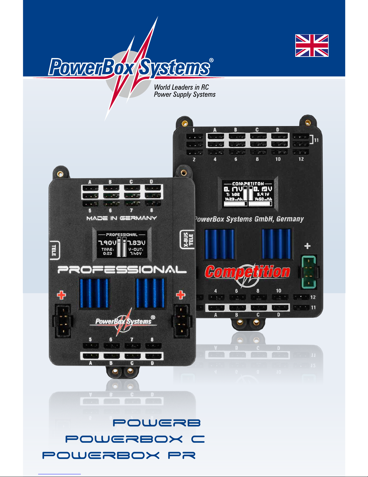
PowErBox Cockpit
PowErBox CompEtition
PowErBox ProfEssionAl

2
PowerBox-Systems − World Leaders in RC Power Supply Systems
Dear customer,
We are delighted that you have decided to purchase a power supply unit
from PowerBox-Systems.
We hope you have many hours of pleasure and great success with your new
PowerBox.
1. PRODUCT DESCRIPTION
The PowerBox Competition, Cockpit and Professional have undergone
constant development since their introduction in 2009. For example, the
menu system has been improved, and new functions such as telemetry and
the door sequencer assistant have been added.
These PowerBoxes are modern power supply systems which contain all
the electronic components required for modern receivers, servos and models. All the essential components for a secure power supply voltage - ICs,
micro-controllers and electronic circuits - are duplicated.
The outstanding features of this High-End power supply unit are a raft of
the latest innovations such as an integral high-resolution graphic OLED
screen, door sequencer capable of multitasking with Setup Assistant, four
match-channels and the facility to bind to the downlink channels of various
RC system manufacturers.

www.powerbox-systems.com
3
FEATURES:
Integral high-resolution graphic OLED screen with 128 x 64 pixels
Particularly user-friendly menu-based programming using the Sensor-
Switch
Door sequencer: six freely programmable outputs with set-up assistant
Channel lock when undercarriage is retracted
11 channels inclusive one channel for the doorsequencer in the Cockpit
Version
12 channels in the Competition version
8 channels in the Professional version
Signal amplification and interference suppression for all channels
Synchronised servo output for totally synchronous servo response
Variable frame rate, range 9 ms - 21 ms
16-bit processor for fast, high-resolution signal processing
Four match-channels, each for two servos. Accurate adjustment of all
eight servos
Double regulated output voltage for receivers and servos
Can be connected to Jeti, Futaba, Spektrum, HoTT and Multiplex down-
link channel bus systems
Direct transmission of battery voltages and capacities (not Professional)
to the transmitter
Separate voltage and capacity (not Professional) displays for each bat-
tery
Software-selectable servo voltage: 5.9 V or 7.4 V
Minimum value memory displays any voltage collapses
Large-area heat-sinks for high regulator power
Regulator monitor, regulator malfunction indicator
Support for three battery types: LiPo/LiIon, NiMH/NiCd, LiFePo
Suppresses any servo feedback currents which might develop
Can be updated using the PowerBox USB Interface or BlueCom adapter
4
PowerBox-Systems − World Leaders in RC Power Supply Systems
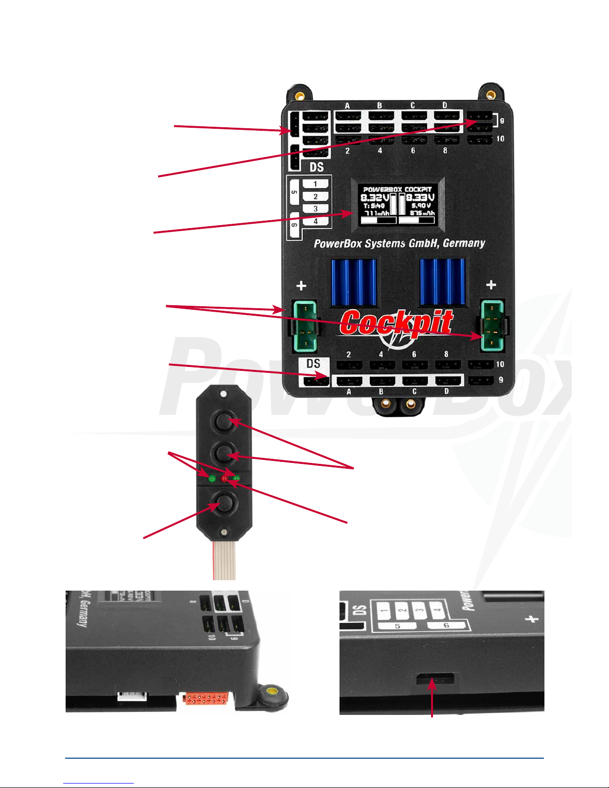
2. CONNECTIONS, CONTROLS
The following illustrations show the essential sockets and controls:
Door sequencer
outputs
Servo sockets
OLED screen
Battery input,
Battery 1 and 2
Receiver inputs
Connector for Jeti, Futaba, Multiplex and HoTT Telemetrie
Left: socket for Spektrum telemetry
Right: SensorSwitch socket
LEDs for power
ON signal
SET-Button
Switch buttons for
Battery 1 and 2
LED for activation

www.powerbox-systems.com
5
3. FIRST STEPS, THE UNIT IN USE:
In the following instructions we do not differentiate between the PowerBox
Cockpit, Competition and Professional, since the method of programming
the three units is absolutely identical. The only difference is that the PowerBox Cockpit includes the door sequencer function.
3.1 CONNECTIONS
Plug the batteries into the MPX connectors on the backer with correct polarity. We recommend PowerPak 2.5 X2 or 5.0 X2. If you prefer to use other
makes of battery, or packs you have assembled yourself, please take parti-
cular care over polarity - it is always better to check twice rather than make
a mistake. If you connect a battery to the backer incorrectly, this will immediately ruin the associated regulator. The unit does not feature reverse polarity
protection, as this minimises power losses between battery and backer. The
+ markings are printed clearly on the case cover.
Connect the SensorSwitch to the appropriate red socket. Note that the
ribbon cable must run upwards. In models subject to powerful vibration we
recommend that you secure the ribbon cable at a minimum of one point in
order to prevent the connector working loose and falling out. Although this
would have no effect on the switched state of the backer, it would prevent
you switching it off.
3.2 THE PROCEDURE FOR SWITCHING ON AND OFF
The method of switching the unit on and off is very simple, and the process
effectively eliminates the possibility of changing the backer’s status accidentally. This is the procedure
Locate the SET button on the SensorSwitch and hold it pressed in until the
central LED glows red. Now press buttons I and II in turn to switch the backer
on.
Repeat the procedure to switch off: hold the SET button pressed in, wait until
the central LED glows red, then confirm by pressing buttons I and II in turn.
Your PowerBox stores the last switched state (on or off). That means: if the
backer is switched off using the SensorSwitch, it stays switched off.

6
PowerBox-Systems − World Leaders in RC Power Supply Systems
Once switched on, the backer can only be turned off again using the switch
unit. Intermittent contacts or interruptions in the power supply cannot cause
the backer to be switched off.
3.3 MAIN SCREEN DISPLAY
When switched on, the unit’s integral screen shows this display:
Key to the individual display points:
- Digital voltage display:
This extremely accurate display allows you to read off the voltage of the battery directly, i.e. the voltage which is present at the input of the PowerBox.
- Graphic voltage display:
A brief glance into the model provides you with information about the batteries’ state of charge. This display is always correct for the type of battery
you have selected. This means that the bar will extend right to the top of the
box if the connected battery is fully charged - assuming that you have set
the correct battery type. If the bar only fills the bottom third of the box, then
the corresponding battery is almost flat. This indicator is supplemented by
the residual capacity display.
- Residual battery capacity (Cockpit/Competition only):
This display shows the momentary capacity value of the battery - again, assuming that you have previously set the battery type correctly. This display
is capable of providing very accurate information about the remaining battery capacity, although ageing effects or defective batteries may falsify the
value. In practice this means that you should always take both values into
account: if the remaining capacity appears to be high, but the voltage has
already fallen to a low level, you should consider it an urgent necessity to
check the battery more closely.

www.powerbox-systems.com
7
- Graphic indicator of battery charge state:
This display is set to match the capacity you previously entered for the batteries connected to the backer. Assuming that the battery is of good quality,
this means: if the bar only reaches the half-way point, then the battery is
still half-full.
- Operating time:
This figure shows the elapsed time since the last RESET. It is important al-
ways to carry out a RESET after each battery charge process.
- Output voltage:
This value displays the backer’s exact output voltage. The voltage fed to the
servos and receiver is the exact value displayed here.
Note: The residual capacity of the two batteries as displayed on the
screen is likely to drift apart as the packs are discharged; this is due to
minor differences in the rate of discharge of the batteries through the
PowerBox. This by no means indicates a fault in the PowerBox; in fact it
proves that the system features genuine redundancy. Here at PowerBox
Systems we take great trouble to compensate for manufacturing tolerances between the two regulators, but it is never possible to produce
a system which is completely devoid of tolerances. The only method of
discharging two batteries at 100% identical rates is to use a system fitted with only one regulator. However, such systems cannot be claimed to
offer redundancy!
3.4 AFTER THE CHARGE PROCESS
The PowerBox must be reset after each charge process, otherwise it is impossible for the unit to display reliable values for energy consumption and
operating times. The latest software release detects a charging process and
resets the capacity counters automatically.
The capacity counters can be reset manually: With the system switched on, locate both buttons I and II on the Sensor-
Switch and press them simultaneously;
hold them pressed in until the following
screen display appears:

8
PowerBox-Systems − World Leaders in RC Power Supply Systems
3.5 BASIC SETTINGS
The PowerBox Cockpit, Competition and Professional feature a new kind
of graphic OLED screen, intended to do away with old-fashioned programming methods based on flashing LED codes, morse code beeps or mechanical jumpers. The screen provides the basis for an extremely user-friendly
control system, and eliminates the need for a supplementary setup unit or
programming device. The SensorSwitch is employed as a convenient means of entering settings within the menu system, and since the Sensor-
Switch is always used as the main ON / OFF switch, it is always installed in
the model, so you cannot forget it. Wherever possible the screen provides
full information in English; few abbreviations are used. The overall result is
an intuitive method of programming which is a great advantage at the flying
field, as you will rarely need to consult the operating instructions.
This is the basic rule in programming: buttons I and II are used to move the
cursor or change values, while the SET button is used to select or confirm
your inputs.
The breadth of functions offered by the PowerBox Cockpit, Competition
and Professional is enormous, but the unit is by no means difficult to operate. To provide a clear idea of the sequence required in order to use the
backer, we have drawn up a brief list of operations
1. Battery setting Point 3.6
2. Servo matching and door sequencer Points 4 and 5
3. Telemetry settings Point 8
3.6 BATTERY SETTINGS
These settings should always be entered first, so that you have an accurate view of the state of the battery while you carry out further adjustments.
In the screenshot below you will see the default settings of the PowerBox
Cockpit, Competition and Professional. If you wish to change them, this is
the procedure:

www.powerbox-systems.com
9
- Switch both batteries on.
- Press the SET button and hold it pressed in until the following display appears:
- Press button II until the cursor (hollow circular ring) lines up with Power
Manager, then press the SET button. The following display now appears:
If you wish to change one of the settings, use buttons I and II to move the
cursor to the appropriate menu point, then press the SET button to select it
(cursor changes to a solid disc). You can now alter the value using buttons
I and II. Once you have selected the desired value, press the SET button to
confirm it; this saves (stores) the new value. Select the menu point OK to
return to the main menu.
Note: the presence of a solid disc (instead of a ring) indicates that you
are in a menu point.
It is possible to alter a value more quickly by holding one of the two buttons I
or II pressed in; the value then starts to change slowly in the corresponding
direction, and the rate of change accelerates with time.
 Loading...