

Page 1
Operating Instruction
Featuring four servo-pulse amplifiers plus
two independent voltage-controllers
Page 2

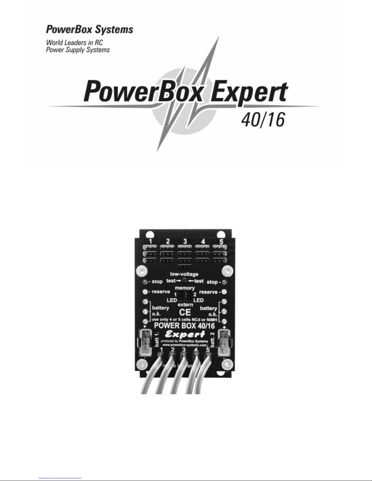
POWER BOX 40/16
- 2 -
Dear Customer,
We are very pleased that you have decided to purchase our POWER BOX 40/16.
With this newly developed product you now have a powerful Dual-Power-control
system for your valuabl e model aeroplane. This will allow you to have not only the
extra safety advantage of coupling two on board flight battery-packs. But to also
have permanent control of the momentary voltag e o f each battery-pack.
Furthermore this latest Dual-Power control unit also includes one powerful servoamplifier for each of the four recei ver-channels. This special feature will enable you
to connect several servos to each receiver line out.
Although this new Dual-Powe r-Control unit is extremely easy to handle you will
need to ha ve some knowledge for it’s correct use. This comprehensi ve manual will
therefore help you to quickly familiarise yourself with your new accessory.
However, in order to fully understand the advantages and safety features of this
unit all we ask is that you carefully read this manual right through before you
commence using your new Dual-Power-Control. We sincerely hope you’ll enjoy
the many safety features we have built into your new POWER-BOX 40/16.
Table of contents
1. Functions of the Dual-Power-Control system........................... Page 2
2. Unit Specifications.................................................................. Page 4
3. Connections and operation controls........................................ Page 5
4. Information on usage and security.......................................... Page 6
5. Warranty information............................................................... Page 7
6. Additional equipment.............................................................. Page 7
1. Function of the Dual-Power control
The POWER BOX 40/16 is a Dual-Power-Control system which besides it’s main
function of being a power control unit – it also displays the momentary voltage of
both of the two connected battery packs by a line of 5 ultra bright LEDs. Therefore
you are always able to check the exact voltage of the two battery packs. This
feature allows you to continually check if there’s enough energy left in either of your
two battery packs for another long thermic-flight.
In addition you can also connect up to four servos covering the four most important
channels of your model -aeroplane to the Dual-Power-Control without causing any
problems. This is because the servo-pulses for each of the four channels connected
Page 3

POWER BOX 40/16
- 3 -
are correctly amplified by a powerful precise on board operation al amplifier, which
special feature allows you to use extra long servo extension wires of up to 2:metres
between the servos and the recei ver without causing the servos any problems.
It is necessary to decouple the two battery packs. This is provided by a very
powerful Dual-Schottky-Diode. Here, the two diodes are in one package.
This new type of diode allows only minimal voltage drops. Therefore it is absolutely
safe to use the Dual-Power-Control with battery packs made up of four cells only.
The POWER BOX 40/16 operates with two battery-packs of the same size and
voltage; this then means that both battery-packs get discharged steadily. While
operating it’s always the battery with the highest momentary voltage, which will be
stressed. Therefore both battery-packs must have the same number of cells and
must also be of the same capacity. So it’s important that you only use two identical
capacity battery-packs.
During flying you can use the whole capacity of both battery-packs. When one
battery-pack diminishes to the pre-set level the second one will immediately cut in
to provide the necessary power-supply for the receiver and servos. By using our
two special hea vy -duty switches along with our double cable circuitry we provide
you maximum flight security.
The POWER BOX 40/16 is also equipped with two independent voltage-controllers
in order to check the voltage of both sources of energy. Five coloured LEDs display
the momentary voltage of each battery-pack: 3-Green, 1-Orange and 1-Red LED
displays the momentary voltage situation. You should therefore check the battery
packs before each flight.
In fact we suggest that you mo ve the Transmitter control stick in order to make the
servos move briefly. By this method you will of course put a slight stress the
battery-pack. But as long as the battery display shows the green LEDs lit up then
the capacity of the accu-pack is high enough for further use. However, if the Orange
LED lights, then you must recharge your battery-packs and you should not start for
reasons of safety.
Should the Red LED light up then stop flying immediately! This indicates that both
battery packs must
be recharged fully, the Red LED display means that they have
been discharged to the there lower limit of capacity.
The LED display is non-linear, it is adjusted to the performance of today’s NiCd –
and NiMH – batteries. Therefore you can control your battery-packs safely and
more precisely. W e recommend that you let us check the optimal adjustments of
the on board Voltage-Controller every two years. We cannot of course give you any
information on how long your battery-pack will last because this depends on the
capacity of the battery-pack used as well as the total number of ser vos installed in
your model and the number of command signals given.
Page 4

POWER BOX 40/16
- 4 -
You can also use the voltage control of our POWER BOX 40/16 in order to check
for any defect cables, plugs and switches etc. If one of these components is
damaged, a higher voltage drop is displayed by the LEDs. It is important that you
repair the damage indicated before getting your model airplane airborne again.
Our Dual-Power-Control system provides each of the four recei ver line-outs with a
powerful precise servo-pulse-amplifier. On the one hand you are able to connect up
to eight servos on just one cha nnel. Long cables runs used for ser vos in the wings
of large models will not cause you any problems when used with the Power-Box
40/16. This is because all of the servos connected to your Power Box will receive
an exact impulse with complete amplitude due to the precision of the amplifi ers
used.
The servo-pulse-amplifier also protects the receiver from interference pulses, which
are produced when using such long servo-cables. This feature also provides an
even high er level o f flight security.
2. Specifications
Working voltage: 4 V to 8 V
Power supply: 2 NiCd respectively NiMH accu packs
with 4 or 5 cells
Power input: approx. 230 mA
Voltage loss: approx. 0.25 V
Servo-conn ections: 16 slots with up to 2 servos each
Max constant current: 2 x 20 A
Temperature range: -10° C to +55° C
Size: 91 x 65 x 18 mm (without base plate)
Weight: 77:grams.
Page 5

POWER BOX 40/16
- 5 -
3. Connections and operation controls
The power supply of the recei ver is provi ded by four servo-cables. Please connect
the servos to the channels of your receiver to which the servo-pulses should be
amplified due to extra number of servos connected to the Power-Box line-out.
The Channel number at the servo
line-in of the POWER BOX 40/16
is identical to the number of the Rx
output block. Therefore if you
connect connection No:1 with lineout No:2 of say a Graupner/JR
recei ver for example (aileron),
then you can connect up to four
aileron-servos directly. Or up to
eight ser vos via special servo Vcables in the case of an extra
large model-aircraft !
Due to our special circuitry you will
not be troubled by any
attenuations, distortions or
interferences of the ser vo-pulses
should you wish to use cables of
up to two meters in length this is
due to our use of high quality integrated amplifiers.
The two battery-packs are connected via two hig h-currentplugs. The POWER BOX 4 0/16 would of course work with one
battery. But you would not have the extra security of using a
double-power-supply. We are able to deliver matching batterypacks with correct high-current-plugs already fitted. However, if
you want to make the power supply cable yourself, then you
must use two pole-proof high-current-plugs for the connection
to the battery-pack. The plugs must not be connected to the
wrong pole! Also please ensure that the cables are soldered
correctly. Make sure that you take notice of the caption on the
plug and also of this sketch in order to avoi d any wrong
connections. This would of course destroy your dual-powercontrol. Ensure that you have a go od joint space and insulate the "+" and "-"
connections against each other as well as against their surrounding area and make
sure that no short circuit can happen at any time.
High-curren
t
-
plugs
Clamping plate
4 plugs each
channel
Extern LED
plugs
Voltage control
battery
1 and 2
Connection
diagram
To
p
view
+
-
Page 6

POWER BOX 40/16
- 6 -
4. Information on usage and security
Please use only low internal resistance battery-packs of the best quality as a supply
for your flight set. Use battery-packs of a higher capacity for your receiver. If one
battery happens to fail during flight, then the other one will provide enough energy
for the receiver. Use only battery-packs of the same type. It’s the only way for the
safe use of your model aeroplane. You may use high-quality battery-packs from our
stock. We stock battery-packs covering a wide range of possible uses for models of
all types. You can therefore take full advantage of our many yea rs of experience
thus ensuring the total safety of your model aeroplane.
Of course there will be no problem should you wish to connect two independent
recei vers to our power-control unit. But you must
read of the manual that comes
with these receivers concerning the use of the two recei vers in order to avoid any
possible interference. Th e po wer supply for the receiver is provided by the four
servo-connection-cables of the POWER BOX 40/16 to the two servo line-ins for
each recei ver. Please choose the channels for each of the receivers, for which the
impulses are to be amplified.
Place the Dual-Power-Control unit, just like any other part of your on board
aeroplanes flight set, in such a position in your model where it will be safe from any
vi brations. The electronic LED display part of the unit may be damaged if the
vi brations are too severe. But it is impossible that the dual-power-control will ever
break down due to these vibrations. So the power supply necessary to your
recei ver is fully guaranteed at all times.
The clamping-plate has four holes which will help you when installing the switch.
Install the POWER BOX 40/16 in a position which will allow you to see and check
the switch from outside of the plane.
Then connect the two battery-packs to the dual-power-control with a separate
battery switch for each. We would also recommend that you use our special highcurrent switches for easy use.
If you operate first one and then the second switch, you can check the Dual-power
control. The LED’s must display the momentary voltage of the battery-pack. Then
you connect – while you have interrupted the power supply – to the recei ver. The
recei ver set must work even if only on e storage battery is being acti vated. You can
check this fact by switching on the transmitter and moving the rudder.
The Power Box 40/16 fully meets the EMV-Requirements. There fore it has the CE-
badge. The switch is built for use o nly in models and must be used only in remotecontrolled models. You may use it only with D.C., which is provided by a NiCd- or
NiMH-storage battery with a maximum of 5 cells. Don’t use it with power supply.
Page 7

POWER BOX 40/16
- 7 -
5. Warranty information
Each Powe r Box 40/16 has had to pass through several tests during its production
phase. We put special emphasis on producing a very high quality-product. This fact
enables us to give you a guarantee on ou r Dual-power–Control of 24 months from
the day of your purchase. This means that we will repair proven any faults in the
product during this period. We may decide to exchange the switch if a re pair is not
possible.
The dated receipt you receive when buying the unit is the proof for the duration of
the warranty. A repair will not increase the life of the warranty.
Should you damage the switch e.g. by connecting it to the wrong poles, by
exceeding the voltage limit, which is described in the specifications, you will forfeit
your warranty. This also applies should the unit experience any damage due to
heavy wear or excessive vibrations. Further demands on dam ages caused by the
Dual-Power-Control are also excluded. Any demands for damages caused by the
Power Box whilst using it are also excluded.
If you return your Dual-Power-Control, please ensure that you pay all the
necessary forwarding expenses. We cannot accept any non-prepaid packages. We
do no take on any liability for damages due to transport damage or any loss of your
package. In case of a warranty claim please send the switch together with your
voucher to following address. Please also give us a brief description o f the
malfunction noted.
6. Additional equipment
As a connection from battery to the Dual-Power-Control we recommend that you
use our special High-Current switches at all times. These specially produced
switches are adjusted to suit our POWER BOX 40/16. They can manage the higher
current required far better than any othe r switch now being used for flight sets in
modelling.
Our High-Current-switches offer real security. This will provide a safe connection
by using 8 independent contacts for switching the “+”-pole. A green LED is
integrated into our each high-current switch. This bright LED shows you the
momentary situation of the switch.
Furthermore an extra feature is a plug -in socket for recha rging built into the switch
housing which can handle a recharging voltage of up to 2 A. But we want to point
out that fast charging via this plug-in isn’t possible with some battery chargers. In
this case we recommend that you rapid charge directly via an accumulator-plug. By
Page 8

POWER BOX 40/16
- 8 -
using our special High Current switches you will of course increase the safety factor
when flying for your model aero plane.
If it is not possible to install your POWER BOX 40/16 in a prominent position where
you can see the LED’s easily. Then we are able to offer you the possibility to
connect two extra bright LED’s for each of the battery packs. You can install these
ultra bright LEDs in a prominent position in your mod el. You will then be warned of
any voltage-drop when you see the bright LED shining.
We trust that you will enjoy modelling with your new Dual-Power-Control system.
Donauwoerth, Oct. 2001
PowerBox Systems
Modellbau-Deutsch
Hindenburgstraße 33
86609 Donauwörth
Tel: +49-0906-225 59
Fax: +49-0906-22459
info@PowerBox-Systems.com
www.PowerBox-Systems.com
 Loading...