

PowerBoss PHOENIX 30, PHOENIX 34, CP 2832 User Manual
PHOENIX 30/34
WALK-BEHIND SCRUBBER
•User Manual
This manual is for the POWERBOSS PHOENIX 30/34 This manual provides the
necessary operating and preventive maintenance instructions. Operators must read and
understand this manual before operating or servicing this machine.
This machine was designed to give you excellent performance and efficiency. For best
results and minimal cost, please follow the general guidelines below:
Operate the machine with reasonable care.
Follow the manufacturers suggested maintenance instructions as provided in this
booklet.
Use original PowerBoss supplied parts.
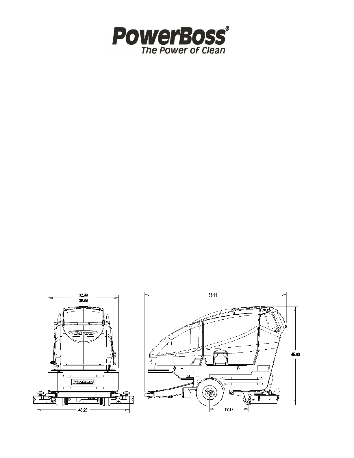
TECHNICAL SPECIFICATIONS
Model PHOENIX
Model No. PHOENIX 30/34
Current 70 Amps
Voltage, Batteries 36 volts, 6-6volt
Battery Capacity 275 AH
Sound Level 72dB
Dimensions (LxWxH) 66” x 44” x 47” (167.64cm x 111.76cm x 119.38cm)
Gross Weight 1,020 lbs (462.66 kg) with batteries
614 lbs (278.51 kg) without batteries
Working Grade Transport 16% (10° )
Working Grade Cleaning 10% (7° )
Inflate Wheel Pressure to 50 PSI (Front Wheel)

IMPORTANT SAFETY INSTRUCTIONS
Operators must read and understand this manual before operating or
maintaining this machine.
Do not operate this machine in flammable or explosive areas.
This machine is designed solely for scrubbing dirt and dust in an indoor environment.
PowerBoss does not recommend using this machine in any other capacity.
The following information below may cause a potential hazard to the operator and
equipment. Read this manual carefully and be aware when these conditions can exist.
Take necessary steps to locate all safety devices on the machine and train the
personnel operating the machine. Report any machine damage or faulty operation
immediately. Do not use machine if it is not in proper operating condition.
FOR SAFETY DURING OPERATION:
Keep hands and feet clear of moving parts while machine is in operation.
Make sure all safety devices are in place and operate properly. All covers, doors and
latches must be closed and fastened before use.
During operation, attention should be paid to other persons in the work area and
especially if small children are present.
Electric motors and components can cause an explosion when operated near
explosive materials or vapor. Do not operate this machine near flammable materials
such as solvents, thinners, fuels, grain dust, etc.
Store or park this machine on a level surface only, with parking brake engaged. To
prevent unauthorized use, machine should be stored or parked with the key removed.
This machine is designed for level operation only. Do not operate on ramps or
inclines.
This machine is not suitable for picking up hazardous dusts.
Use caution when moving this machine into areas that are below freezing
temperatures. Any water in the tanks or hoses can cause damage to the machine.
FOR SAFETY WHEN SERVICING or MAINTAINING MACHINE:
Stop on level surface.
Disconnect the power to the machine by pulling the large red handle (Anderson Plug)
located in the back of the machine, mid-right, when charging batteries or during
installation or removal of brushes.
Avoid moving parts. Do not wear loose jackets, shirts, or sleeves when working on
machine.
Avoid contact with battery acid. Battery acid can cause burns. When working on or
around batteries, wear protective clothing and safety glasses. Remove metal jewelry.
Do not lay tools or metal objects on top of batteries.
Charging batteries generates explosive gasses. Do not charge batteries when open
flames or sparks are present. Do not smoke. Make sure the charger is turned off
before disconnecting it from the machine.
Charge the batteries in a well-ventilated area with the battery cover removed
completely.
Do not clean machine with a pressure washer.
Authorized personnel must perform repairs and maintenance. Use PowerBoss
supplied replacement parts.
SAVE THESE INSTRUCTIONS
3

INSPECTION
Carefully unpack and inspect your Phoenix walk behind scrubber for shipping damage.
Follow unpacking instructions on shipping pallet. Each unit has been tested and
thoroughly inspected before shipment. Any damage is the responsibility of the delivery
carrier who should be notified immediately.
ELECTRICAL
This machine is battery operated and designed to operate on 36 volts DC (6) 6-volt
batteries.
BATTERIES
The recommended batteries are rated 275Ah (P/N 956740).
We do not recommend mixing AMP hour capacities. Any alternate battery sets can be
used if they equal physical size and capacity. See page 13 for service and installation.
OPERATOR RESPONSIBILITY
Read this manual carefully before operating this machine.
The operator is responsible in taking care of the daily maintenance and check ups of
the machine to keep it in good working condition. The operator must inform the service
mechanic or supervisor when the scheduled maintenance intervals are required as
stated in the MAINTENANCE section of this manual.
Before starting familiarize yourself with the machine and its controls (see “Machine
Overview, Front”, “Machine Overview, Rear”, “Operator Compartment”, “Control
Console” diagrams).
MACHINE COMPONENTS
FRONT
ROLLER BUMPERS
A
RECOVERY TANK
B
C
D
E
F
CONTROL CONSOLE
G
H
I
J
K
SOLUTION TANK
FRONT WHEEL
REAR CASTER
REAR SQUEEGEE
CUP HOLDER
VACUUM COVER
TANK LID
DUMP CAP COVER
J
C
I
H
G
B
K
F
A
E
D
4

MACHINE COMPONENTS
REAR
A
B
C
D
E
F
G
H
I
CONTROL CO NSOLE
REAR SQUEEGEE
SCRUB DECK
SOLUTION DUMP HOSE
RECOVERY DUMP HOSE
ANDERSON PLUG
DIRECTIONA L SWITCH
HOUR METER
EMERGENCY BELLY BAR
B
A
I
G
E
F
H
D
C
MACHINE COMPONENTS
CONTROL CONSOLE
A
B
C
D
E
F
G
H
I
J
ACCELERATION LEVER
SPEED CONTROL KNOB
DIRECTIONAL INDICATOR
EMERGENCY BELLY BAR
OFF-AISLE WAND SWITCH
DIRECTIONAL LEVER
KEY SWITCH
BATTERY GAUGE
SOLUTION CONTROL
MODE SELECTOR
E
A
I
F
D
C
J
B
H
A
G
5

THE CONTROL CONSOLE
For operator ergonomics, the control console houses all the primary function buttons
are grouped in a central area. The key switch, main keyboard, directional switch and
off-aisle wand switch are clustered in the back area. The directional switch (forward
and reverse) is located in front of the console for easy fingertip operation.
Accelerator Lever
(A) Enables the machine to move forward or backwards once depressed.
Speed Control
(B) This knob controls the rate at which the machine moves. Turning the knob
clockwise will increase the speed. Turning the knob counter-clockwise will decrease
the machine speed.
Directional Switch
(C) When you flip the switch down, the machine moves backwards or flip the switch
upward, the machine will go forward.
Directional Indicator
(D) This indicator displays which direction the Phoenix will travel once the Accelerator
Lever is depressed. A light is available for each direction. Amber when set to
forward. Red when set to reverse.
Key switch
(E) Controls the machine’s power (On/Off) with a key for safety. All operational
settings are retained even when the power is turned off and on. This also serves as a
reset switch when error or fault codes.
Emergency Belly Bar
(F) If this bar is to be depressed it will override the directional switch and force the
Phoenix to go forward. Most useful if backed into a corner or object to prevent from
pinching the operator.
Off-aisle wand switch
(G) On/Off control for the water supply to the wand and vacuum motor. If the switch is
in the On position it will force the battery gauge to blink 6 LEDs to signify the wand is
currently on.
Battery Gauge
(H) This gauge displays the remaining battery life. The gauge has a readout of 10
LEDs. 3 Green, 4 Amber, 3 Red. This gauge will also display the fault code if the
system has an error represented by the number illuminated flashing LEDs. See
Fault/Diagnostics Codes below for specific code.
If the battery life is low the battery gauge bar icon will be flashing to signal the operator
that the machine is almost out of power. Once this signal is displayed to the operator,
all functions will shut off including the transport mode. The operator has to turn the key
switch OFF and then, ON to reset the machine. The machine then will only have a few
minutes left of reserve power for a short Vacuum only mode to pick up remaining
solution on the floor and Transport power.
Solution Control
(I) This knob controls the rate at which solution is put down. Turning the knob
clockwise will increase the amount of solution put down. Turning the knob counterclockwise will decrease the solution rate. The knob can be adjusted between 0.25
gpm up to 1.1 gpm.
6
 Loading...