

PowerBoss PB620DSL, PB620LP, PB620DSL-DSB, PB620GAS-DSB, PB620LP-DSB User Manual
...
User Manual
Atlas Sweeper
Models: Diesel, Gasoline, & LPG
PB# 4100053 Rev. B 05/15
PowerBoss®, Minuteman International, Inc.
A Member of the Hako Group

Minuteman, International, Inc. Copyright 2011-2015
Atlas Sweeper #4100053UM Rev. B 05/15
Page 2
PREFACE
PREFACE
Thank you for your purchase of the new industry standard for scrubber/sweepers. PowerBoss® takes
great pride in offering the most dependable, reliable and best value in industrial power scrubbers and
sweepers. We set the standard.
Our Customer Service Department would like to hear from you. If you see any errors, omissions or
something that needs clarication in this User Manual, please let us know. We are working hard
towards continually improving our processes to benet you, our valued customer.
Please copy the form on the next page. Fill out and comment on how you found our manual.
Thank you!
The PowerBoss Team

Atlas Sweeper #4100053UM Rev. B 05/15
Minuteman, International, Inc. Copyright 2011-2015
Page 3
PREFACE
Name: _____________________________________________
Title: _______________________________________________
Company Name: _____________________________________
Address: ____________________________________________
Country: ____________________________________________
Type of equipment or model number: ______________________
Comments: ___________________________________________________________________
_____________________________________________________________________________
_____________________________________________________________________________
Please return to:
Customer Service Manager
PowerBoss®, Minuteman International, Inc.
14N845 U.S. Route 20
Pingree Grove, Illinois 60140 USA
Phone: (800) 323-9420
Email: tech@powerboss.com

Minuteman, International, Inc. Copyright 2011-2015
Atlas Sweeper #4100053UM Rev. B 05/15
Page 4
PREFACE
This is the User Manual for the PowerBoss® Atlas Rider Sweeper.
This manual covers all Standard Atlas machine variations beginning May 2015.
We believe this machine will provide excellent service for many years.
However, the best results will be obtained if:
• The machine is operated with reasonable care.
• The machine is maintained regularly per the maintenance schedule provided in this User Manual.
• The machine is maintained with PowerBoss® supplied or equivalent parts.
All right side and left side references to the machine (except for engine) are determined by facing the
direction of forward travel. The front of the engine or engine fan faces the left side of the machine.
Some hardware considered to be common or locally available has been omitted from the parts section
to make this manual clear. Be sure to use equivalent hardware when replacement becomes necessary.
The Model and Serial Number of your machine is shown on the I.D. name plate. This information is
needed when contacting Technical Support or when ordering parts. The I.D. plate is mounted on the left
side wall of the operator seating area.
Example I.D. Plate:

Atlas Sweeper #4100053UM Rev. B 05/15
Minuteman, International, Inc. Copyright 2011-2015
Page 5
PREFACE
Parts may be ordered by phone, fax or e-mail from your local PowerBoss® parts and service center.
Before ordering parts or supplies, be sure to have your machine Model Number and Serial Number
handy. For your convenience Fill out the Machine Data block for future reference.
MACHINE DATA
Fill out at installation
Model Number: ___________________________________
Serial Number: ___________________________________
Engine Serial Number: _____________________________
Sales Rep.: _________________ Date of Install: ________
All information contained in this catalog is current at the time of printing.
Minuteman International, Inc. reserves the right to make changes at any time without notice.
PowerBoss®, Minuteman International, Inc., Copyright 2011-2015, Printed in USA

Minuteman, International, Inc. Copyright 2011-2015
Atlas Sweeper #4100053UM Rev. B 05/15
Page 6
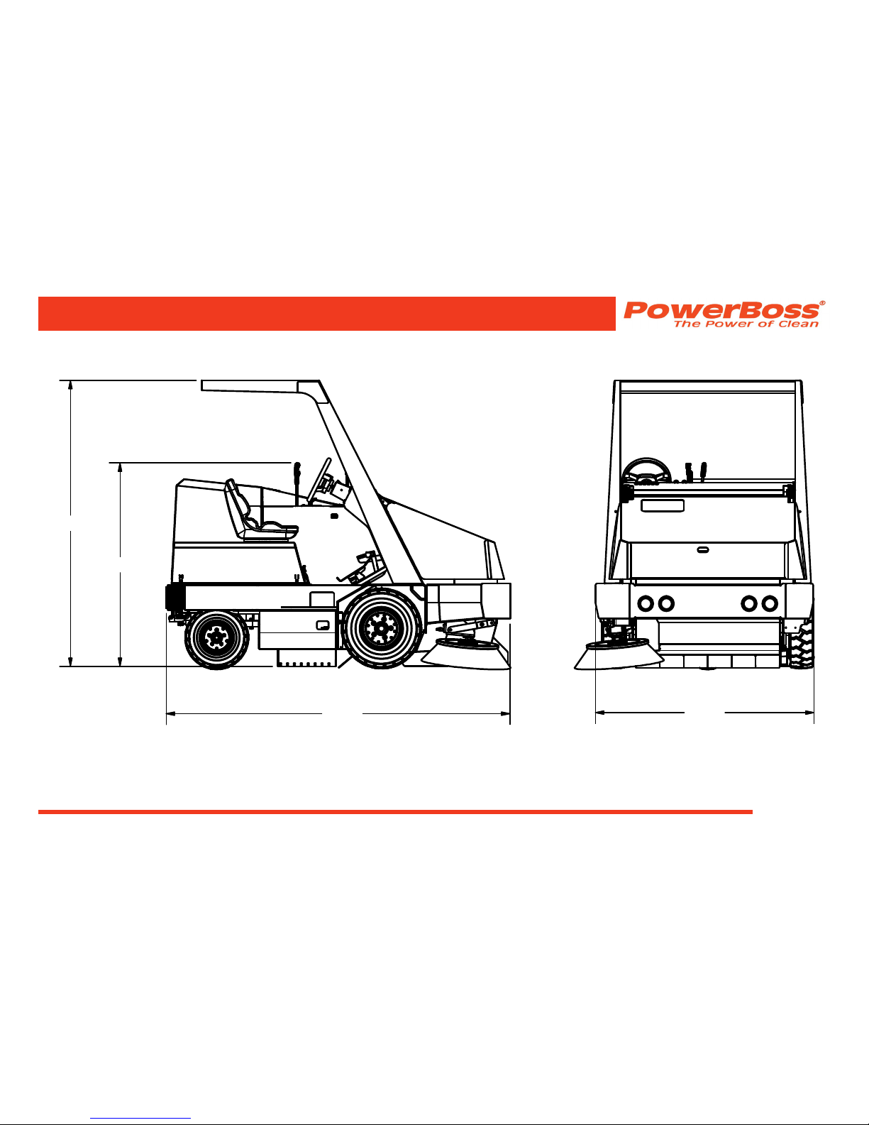
TECHNICAL SPECIFICATIONS
Model: Atlas Sweeper Atlas Sweeper w/Dual Side Broom
Model No.: PB620DSL, PB620GAS, PB620LP PB620DSL-DSB, PB620GAS-DSB, PB620LP-DSB
GENERAL MACHINE SPECIFICATIONS
Length:. . . . . . . . . . . . . . . . . . . . . . . 99.75 in
Width without side broom . . . . . . . . 63.38 in
Rear frame width: . . . . . . . . . . . . . . 60.00 in
Height w/ overhead guard . . . . . . . . 82.88 in
Height w/ overhead guard . . . . . . . . 58.88 in
Wheelbase: . . . . . . . . . . . . . . . . . . . 47.75 in
Aisle width U-turn: . . . . . . . . . . . . . . 10.0 ft (120 in)
(contact clearance = 113 in)
Empty vehicle weight . . . . . . . . . . . 3460 lbs
Gross vehicle weight . . . . . . . . . . . . 4660 lbs
Sound level:. . . . . . . . . . . . . . . . . . . 83 dBa
Maximum forward speed: . . . . . . . . 9.8 mph
Maximum reverse speed: . . . . . . . . 3 mph
Maximum climb angle
empty hopper: . . . . . . . . . . . . . . . . . 14 degrees (24.9 % grade)
Maximum climb angle full hopper . . 10 degrees (17.6% grade)
TECHNICAL SPECIFICATIONS
SWEEPING SYSTEM
Productivity . . . . . . . . . . . . . . . . . . . 184,800 sq. ft. per hour
Main broom diameter: . . . . . . . . . . . 14.0 in
Main broom length: . . . . . . . . . . . . . 48.0 in
Side broom diameter: . . . . . . . . . . . 26.0 in
Sweeping path w/ side broom . . . . . 63 in
Optimum main broom
pattern width:. . . . . . . . . . . . . . . . . . 2.0 in – 2.5 in
Hopper weight capacity: . . . . . . . . . 1200 lbs.
Hopper volumetric capacity
(less lter box): . . . . . . . . . . . . . . . . 16.0 cu ft
Hopper dump height:. . . . . . . . . . . . variable to clear 60 in
Min. ceiling height
for 60” hopper dump:. . . . . . . . . . . . 8 ft – 6 in
Filter type: . . . . . . . . . . . . . . . . . . . . Treated synthetic panel lter
Filter area: . . . . . . . . . . . . . . . . . . . . 95 sq ft
Atlas Sweeper #4100053UM Rev. B 05/15
Minuteman, International, Inc. Copyright 2011-2015
Page 7
TECHNICAL SPECIFICATIONS
58.88
82.88
99.75
63.38

Minuteman, International, Inc. Copyright 2011-2015
Atlas Sweeper #4100053UM Rev. B 05/15
Page 8
TABLE OF CONTENTS
PREFACE. . . . . . . . . . . . . . . . . . . . . . . . . . . . . . 2
TECHNICAL SPECIFICATIONS . . . . . . . . . . . 6
GENERAL MACHINE SPECIFICATIONS . . . . . . . . . . 6
SWEEPING SYSTEM . . . . . . . . . . . . . . . . . . . . . . . . . . 6
FEATURES . . . . . . . . . . . . . . . . . . . . . . . . . . . . 12
AIR-MOVING SYSTEM . . . . . . . . . . . . . . . . . . . . . . . . . 12
DEBRIS-HANDLING SYSTEM. . . . . . . . . . . . . . . . . . . 12
SAFETY INNOVATIONS . . . . . . . . . . . . . . . . . . . . . . . . 13
ERGONOMICS SYSTEM . . . . . . . . . . . . . . . . . . . . . . . 13
HYDRAULIC SYSTEM . . . . . . . . . . . . . . . . . . . . . . . . . 13
DRIVE-TRAIN SYSTEM . . . . . . . . . . . . . . . . . . . . . . . . 13
CHASSIS SYSTEM . . . . . . . . . . . . . . . . . . . . . . . . . . . . 14
POWERBOSS INNOVATIONS . . . . . . . . . . . . . . . . . . . 14
ENVIRONMENTAL FRIENDLY FEATURES . . . . . . . . 14
CLEAN AIR . . . . . . . . . . . . . . . . . . . . . . . . . . . . . . . 14
LOWER EMISSIONS . . . . . . . . . . . . . . . . . . . . . . . . 14
SAFER WORK ENVIRONMENT. . . . . . . . . . . . . . . 14
SAFETY INFORMATION . . . . . . . . . . . . . . . . . 15
IMPORTANT SAFETY INSTRUCTIONS . . . . . . . . . . . 15
FOR SAFETY DURING OPERATION . . . . . . . . . . . . . 15
FOR SAFETY WHEN SERVICING & MAINTAINING
MACHINE . . . . . . . . . . . . . . . . . . . . . . . . . . . . . . . . . . . . 16
SAFETY SYMBOLS . . . . . . . . . . . . . . . . . . . . . . . . . . . 17
SAFETY DECALS . . . . . . . . . . . . . . . . . . . . . . . . . . . . . 18
BASIC POWERBOSS® SAFETY . . . . . . . . . . 21
MACHINE OPERATION . . . . . . . . . . . . . . . . . . 24
BASIC OPERATING CONTROLS & INDICATORS 24
IGNITION SWITCH . . . . . . . . . . . . . . . . . . . . . . . . . 24
THROTTLE / GLOW PLUG SWITCH . . . . . . . . . . . 24
LIGHT SWITCH . . . . . . . . . . . . . . . . . . . . . . . . . . . . 24
HORN BUTTON . . . . . . . . . . . . . . . . . . . . . . . . . . . . 24
FUEL LEVEL GAUGE . . . . . . . . . . . . . . . . . . . . . . . 24
HOUR METER . . . . . . . . . . . . . . . . . . . . . . . . . . . . . 24
TABLE OF CONTENTS

Atlas Sweeper #4100053UM Rev. B 05/15
Minuteman, International, Inc. Copyright 2011-2015
Page 9
INDICATOR LIGHTS . . . . . . . . . . . . . . . . . . . . . . . . 26
Clogged lter light (optional) . . . . . . . . . . . . . . . . 26
Fire in the hopper light . . . . . . . . . . . . . . . . . . . . . 26
Hopper Door Closed light. . . . . . . . . . . . . . . . . . . 26
Check Engine light . . . . . . . . . . . . . . . . . . . . . . . . 26
Engine oil pressure light . . . . . . . . . . . . . . . . . . . . 26
Engine Coolant Temperature light . . . . . . . . . . . . 26
DIRECTIONAL CONTROL PEDAL . . . . . . . . . . . . . 26
BRAKE / PARKING BRAKE. . . . . . . . . . . . . . . . . . . 27
TILT STEERING LEVER . . . . . . . . . . . . . . . . . . . . . 27
SEAT ADJUSTMENT . . . . . . . . . . . . . . . . . . . . . . . . 27
SWEEPING CONTROLS . . . . . . . . . . . . . . . . . . . . . . . 28
BROOM CONTROL LEVER . . . . . . . . . . . . . . . . . . 28
MAIN BROOM LEVER. . . . . . . . . . . . . . . . . . . . . . . 28
MAIN BROOM ADJUSTMENT . . . . . . . . . . . . . . . . 28
MAIN BROOM WEAR INDICATOR . . . . . . . . . . . . 28
SIDE BROOM LEVER . . . . . . . . . . . . . . . . . . . . . . . 28
IMPELLER SWITCH . . . . . . . . . . . . . . . . . . . . . . . . 28
DEBRIS HOPPER DUMP CONTROLS . . . . . . . . . . . . 30
HOPPER FILTER SHAKER BUTTON . . . . . . . . . . 30
HOPPER RAISE / LOWER LEVER . . . . . . . . . . . . 30
HOPPER DOOR LEVER . . . . . . . . . . . . . . . . . . . . . 30
OPERATING PROCEDURES . . . . . . . . . . . . . . . . . . . . 32
PRE-OPERATION CHECKS . . . . . . . . . . . . . . . . . . 32
STARTING . . . . . . . . . . . . . . . . . . . . . . . . . . . . . . . . 32
DRIVING . . . . . . . . . . . . . . . . . . . . . . . . . . . . . . . . . . 33
SLOWING AND STOPPING . . . . . . . . . . . . . . . . . . 33
OPERATING INCLINES/SLIPPERY SURFACES 33
SWEEPING . . . . . . . . . . . . . . . . . . . . . . . . . . . . . . . . 33
STOP SWEEPING . . . . . . . . . . . . . . . . . . . . . . . . . . 34
EMPTYING THE HOPPER . . . . . . . . . . . . . . . . . . . 34
STOPPING THE MACHINE . . . . . . . . . . . . . . . . . . 35
TRANSPORTING THE MACHINE . . . . . . . . . . . . . 35
Using a Trailer or Transport Vehicle. . . . . . . . . . . 35
Pushing or towing the Machine . . . . . . . . . . . . . . 36
TABLE OF CONTENTS

Minuteman, International, Inc. Copyright 2011-2015
Atlas Sweeper #4100053UM Rev. B 05/15
Page 10
PREVENTATIVE MAINTENANCE . . . . . . . . . . 38
INTRODUCTION . . . . . . . . . . . . . . . . . . . . . . . . . . . . . . 38
SCHEDULED MAINTENANCE CHART . . . . . . . . . . . 39
PREVENTATIVE MAINTENANCE INSTRUCTIONS 43
ENGINE . . . . . . . . . . . . . . . . . . . . . . . . . . . . . . . . . . 43
Air Intake System . . . . . . . . . . . . . . . . . . . . . . . . . 44
Check Air Filter Service Indicator . . . . . . . . . . 44
Air Filter Element Removal. . . . . . . . . . . . . . . 45
Air Filter Cleaning. . . . . . . . . . . . . . . . . . . . . . 45
Air Filter Inspection. . . . . . . . . . . . . . . . . . . . . 45
Air Filter Installation . . . . . . . . . . . . . . . . . . . . 45
ELECTRICAL SYSTEM . . . . . . . . . . . . . . . . . . . . . 46
Battery Cleaning. . . . . . . . . . . . . . . . . . . . . . . . . . 46
Battery Replacement . . . . . . . . . . . . . . . . . . . . . . 46
Circuit Breakers . . . . . . . . . . . . . . . . . . . . . . . . . . 47
Fuses . . . . . . . . . . . . . . . . . . . . . . . . . . . . . . . . . . 47
FUEL SYSTEM . . . . . . . . . . . . . . . . . . . . . . . . . . . . 48
COOLANT SYSTEM . . . . . . . . . . . . . . . . . . . . . . . . 49
Blowing Out Radiator Fins . . . . . . . . . . . . . . . . . . 49
Reverse Flow Flushing. . . . . . . . . . . . . . . . . . . . . 49
LUBRICATION . . . . . . . . . . . . . . . . . . . . . . . . . . . . . 50
Changing Engine Oil . . . . . . . . . . . . . . . . . . . . . . 50
LUBRICATION POINTS . . . . . . . . . . . . . . . . . . . . . 50
Steering Cylinder Rod End. . . . . . . . . . . . . . . . . . 50
Steering Pivot Thrust Bearing . . . . . . . . . . . . . . . 50
Main and Side Broom Lift Pulleys . . . . . . . . . . . . 51
Hopper Lift Bearing . . . . . . . . . . . . . . . . . . . . . . . 51
Latches & Hinges . . . . . . . . . . . . . . . . . . . . . . . . . 52
HYDRAULICS SYSTEM . . . . . . . . . . . . . . . . . . . . . 52
Filling The Fluid Reservoir . . . . . . . . . . . . . . . . . . 52
Hydraulic Fluid Viscosity Specications . . . . . . . . 53
Maintaining Hydraulic Oil Cooler Efciency . . . . . 53
Changing The Hydraulic Fluid . . . . . . . . . . . . . . . 54
Changing The Hydraulic Fluid Filter. . . . . . . . . . . 54
Hydroback Pump Centering Unit . . . . . . . . . . . . . 56
Testing Hydroback Pump Centering Unit . . . . 56
Adjusting Propulsion Pump Neutral Setting 56
Inspecting Drive Assemblies/brooms for Debris 58
Broom Door Skirt Replacement and Adjustment 59
Remove and Replace Door Skirts . . . . . . . . . 59
Adjust Door Skirts. . . . . . . . . . . . . . . . . . . . . . 59
TABLE OF CONTENTS

Atlas Sweeper #4100053UM Rev. B 05/15
Minuteman, International, Inc. Copyright 2011-2015
Page 11
Broom Rear Skirt Replacement and Adjustment 59
Remove and Replace Rear Skirt . . . . . . . . . . 59
Adjust Rear Skirt. . . . . . . . . . . . . . . . . . . . . . . 59
Broom Recirculating Flap Inspection . . . . . . . . . . 59
Broom Recirculating Flap Replacement . . . . . . . . 59
Main Broom Height Adjustment . . . . . . . . . . . . . . 60
Main Broom Rotation or Replacement . . . . . . . . . 61
Main Broom Taper and Sweep Pattern Test. . . . . 62
Main Broom Taper Adjustment . . . . . . . . . . . . . . . 64
Side Broom Height (Wear) Adjustment . . . . . . . . 65
To Adjust The Side Broom Height . . . . . . . . . 65
Side Broom Shock Mount Stop Adjustment . . . . . 66
Side Broom Replacement . . . . . . . . . . . . . . . . . . 66
HOPPER . . . . . . . . . . . . . . . . . . . . . . . . . . . . . . . . . . 67
Filter Removal . . . . . . . . . . . . . . . . . . . . . . . . . . . 67
Filter Cleaning . . . . . . . . . . . . . . . . . . . . . . . . . . . 67
Filter Replacement . . . . . . . . . . . . . . . . . . . . . . . . 67
Hopper Frame Skirt Replacement . . . . . . . . . . . . 68
Top Hopper Frame Skirt . . . . . . . . . . . . . . . . . 68
Wheel Well Skirts . . . . . . . . . . . . . . . . . . . . . . 68
Adjusting The Parking Brake Cable Length . . . . . 69
TIRES . . . . . . . . . . . . . . . . . . . . . . . . . . . . . . . . . . . . 70
Changing Solid Tires . . . . . . . . . . . . . . . . . . . . . . 70
Changing Pneumatic Tires. . . . . . . . . . . . . . . . . . 70
MISCELLANEOUS ADJUSTMENTS . . . . . . . . . . . 70
Anti-Static Chain Adjustment . . . . . . . . . . . . . . . . 70
Latch and Hinge Maintenance . . . . . . . . . . . . . . . 70
Cables . . . . . . . . . . . . . . . . . . . . . . . . . . . . . . . . . 70
TROUBLESHOOTING . . . . . . . . . . . . . . . . . . . 71
TROUBLESHOOTING CHART . . . . . . . . . . . . . . . . . . 71
WARRANTY. . . . . . . . . . . . . . . . . . . . . . . . . . . . 78
TABLE OF CONTENTS

Minuteman, International, Inc. Copyright 2011-2015
Atlas Sweeper #4100053UM Rev. B 05/15
Page 12
FEATURES
FEATURES
AIR-MOVING SYSTEM
• Four-stage dust ltration
- Vacuumized main broom chamber
- Removable pre-ltering for large particle removal
- 95 Sq. Ft. synthetic dust control lter panel
- Advanced electric lter shakers design that
shakes lter element
• User friendly ltration system design no need to
remove shaker motor to remove lter element
• Double layered mounting of hydraulic impeller for
reduced noise
• Engine area shielded from exhaust air, which is
vented at the rear of the machine
• Fire-in-hopper Indicator will automatically shut off
impeller fan
• Optional clogged Filter Indicator
DEBRIS-HANDLING SYSTEM
• High wear rubber skirts equipped with indicators for
wear, adjustment and replacement
• Shock mounted side broom, employs trailing arm
design to prevent accidental damage
• Quick change 26” side broom
• Direct throw sweeping method
• Oversized hopper
• Innovative main broom adjustment system
- Fully adjustable from operator compartment
- Full oat feature
- Visual broom wear indicator from operator
compartment
- Lever position for quick and simplied broom
replacement
• Impeller shut off for wet sweeping from operator
compartment
• Dual-performance sweep mode
• Multi-Level Hopper Dumping

Atlas Sweeper #4100053UM Rev. B 05/15
Minuteman, International, Inc. Copyright 2011-2015
Page 13
SAFETY INNOVATIONS
• Vehicle speed restriction when hopper is raised
• Hopper safety arm accessible without need to reach
under raised hopper
• Safety vision feature allows forward visibility with
hopper raised
ERGONOMICS SYSTEM
• Roomy, open operator compartment for extra comfort
• Toe operated parking brake
• Adjustable, high-back seat
• Power steering and tilt steering wheel
• Comfortable pedal/controls placement
• Unparalleled maintenance accessibility, cover
removal requires no tools
• Simplied color coded operator controls for sweep
and dump functions.
HYDRAULIC SYSTEM
• Hydraulic lter built into reservoir for ease of
maintenance
• Protection for both auxiliary and propulsion pumps
using separate 100 mesh lters
• Hydraulic reservoir equipped with site gauge and dip
stick for uid level check and replacement
• Hydraulic lter equipped with color coded pressure
gauge to indicate lter replacement
DRIVE-TRAIN SYSTEM
• Industrial liquid-cooled engine
• Heavy-duty radiator & Tri-phase air cleaner
• Hydraulics protection package
• 4-Core Radiator
• PowerClimb™ All-Terrain Access
(Two 23-1/4” OD Pneumatic Front Tires & single
18 1/2” OD Pneumatic Rear Tire)
FEATURES

Minuteman, International, Inc. Copyright 2011-2015
Atlas Sweeper #4100053UM Rev. B 05/15
Page 14
FEATURES
CHASSIS SYSTEM
• Massive One-Piece, unitized 1/4 thick steel frame
• Oversized, soft-ride tires
POWERBOSS INNOVATIONS
• PowerClimb™ - with oversized tires and extra
ground clearance you can easily negotiate rough
terrain and speed bumps; even climb most sidewalk
curbs
ENVIRONMENTAL FRIENDLY FEATURES
CLEAN AIR
High-performance lter system dramatically reduces the
release of dust and debris back into the air, dust vacuum
ensures that dust is put directly into the hopper, bristle
pattern on main broom increases dust control
LOWER EMISSIONS
All gas and LP engines meet Tier 3 specications, catalyst
mufers, diesel operated available, bio-diesel fuel can be
used in Kubota® engine
SAFER WORK ENVIRONMENT
Orange machines are highly visible to others in the
workplace, simple controls reduce operator error. Machine
equipped with horn, re in hopper indicator, effective
braking system, also available: overhead guard, back-up
alarm, seat belt, warning beacon and others

Atlas Sweeper #4100053UM Rev. B 05/15
Minuteman, International, Inc. Copyright 2011-2015
Page 15
SAFETY INFORMATION
IMPORTANT SAFETY INSTRUCTIONS
Operators must read and understand this manual before
operating or maintaining this machine.
Do not operate this machine in ammable or explosive
areas.
This machine is designed solely for removing dirt, dust and
debris in an outdoor or indoor environment. PowerBoss
does not recommend using this machine in any other
capacity.
The following information indicate a potential hazard to the
operator and equipment. Read this manual carefully and
be aware when these conditions can exist. Take necessary
steps to locate all safety devices on the machine and train
the personnel operating the machine. Report any machine
damage or faulty operation immediately. Do not use
machine if it is not in proper operating condition.
FOR SAFETY DURING OPERATION
Keep hands and feet clear of moving parts while machine is
in operation.
Make sure all safety devices are in place and operate
properly. All covers, doors and latches must be in place,
closed and fastened before use.
During operation, attention should be paid to other persons
in the work area and especially if small children are
present.
Components can cause an explosion when operated near
explosive materials or vapor. Do not operate this machine
near ammable materials such as solvents, thinners, fuels,
grain dust, etc.
Store or park this machine on a level surface only. To
prevent unauthorized use, machine should be stored or
parked with the parking brake set and the key removed.
This machine is designed for level operation only. Do not
operate on ramps or inclines greater than 14 degrees
(24.9% grade).
This machine is not suitable for picking up hazardous dusts.
Use caution when moving this machine into areas that are
below freezing temperatures.
FEATURES

Minuteman, International, Inc. Copyright 2011-2015
Atlas Sweeper #4100053UM Rev. B 05/15
Page 16
FOR SAFETY WHEN SERVICING &
MAINTAINING MACHINE
Stop on level surface, set parking brake and turn off
machine.
Disconnect the power to the machine when servicing.
Avoid moving parts. Do not wear loose jackets, shirts, or
sleeves when working on machine.
Avoid contact with battery acid. Battery acid can cause
burns. When working on or around batteries, wear
protective clothing and safety glasses. Remove metal
jewelry. Do not lay tools or metal objects on top of battery.
Authorized personnel must perform repairs and
maintenance. Use PowerBoss supplied replacement parts.
SAFETY INFORMATION
Atlas Sweeper #4100053UM Rev. B 05/15
Minuteman, International, Inc. Copyright 2011-2015
Page 17
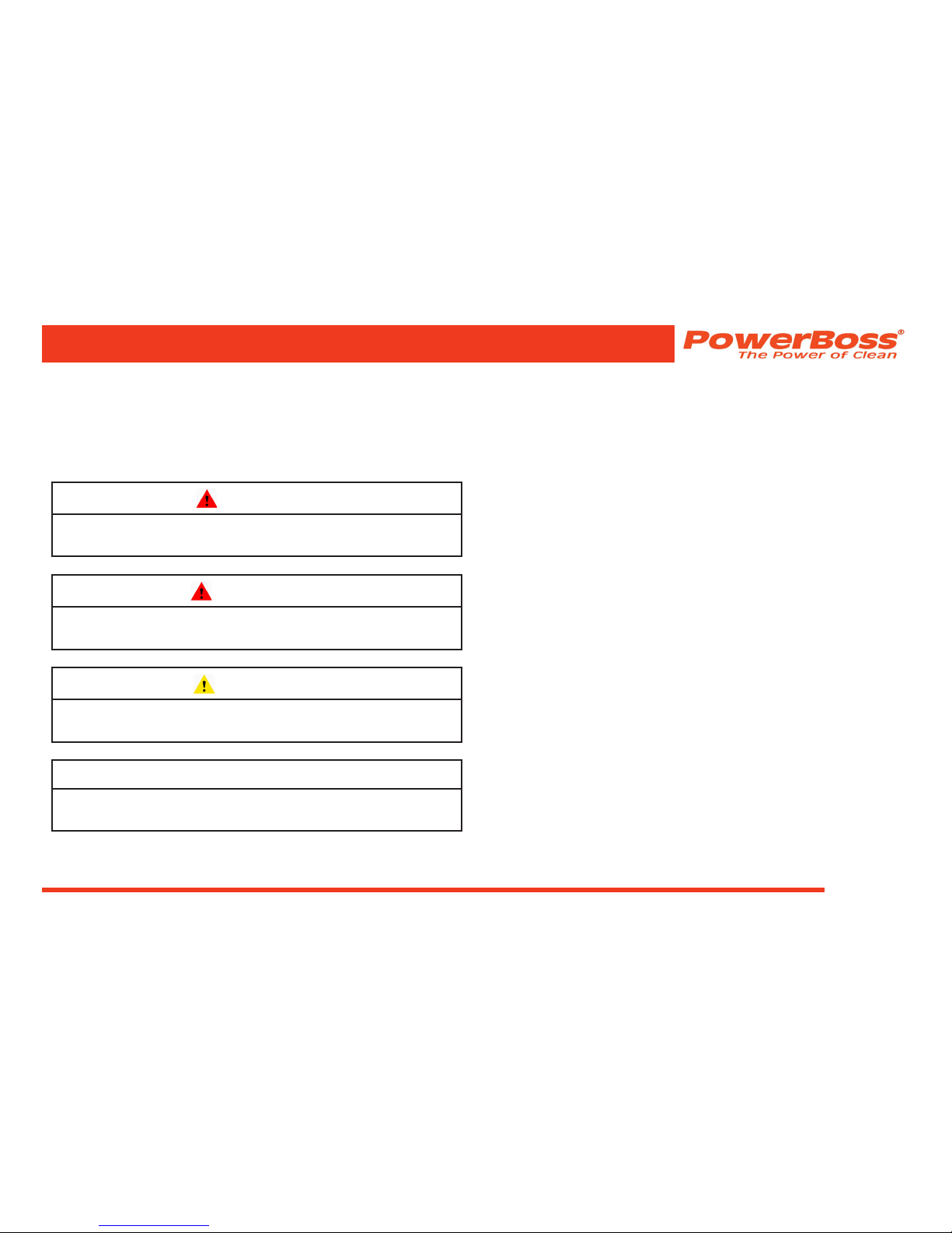
SAFETY SYMBOLS
Five symbols are used throughout this manual to
emphasize various levels of safety information. These
symbols and the meaning of each are listed below.
DANGER
To warn of immediate hazards which will result in
severe personal injury or death
WARNING
To warn of hazards or unsafe practices which could
result in severe personal injury or death.
CAUTION
To warn of hazards or unsafe practices which could
result in minor personal injury.
ATTENTION!
To warn of practices which could result in extensive
equipment damage.
NOTE: To direct your attention to important
equipment information or special instructions
for preventing damage to equipment
Symbols at the top of the list are the strongest warnings.
However, all symbols represent important information which
should be observed to protect you and others from harm
and injury, and to prevent damage to the equipment.
SAFETY INFORMATION

Minuteman, International, Inc. Copyright 2011-2015
Atlas Sweeper #4100053UM Rev. B 05/15
Page 18
SAFETY DECALS
Decals directly attached to various parts of the unit are
highly visible safety reminders which should be read
and observed. Make sure the decals are replaced if they
become illegible or damaged.
Located in the operator compartment:
Part Number 3301854
Located near the Impeller inlet:
Part Number 3301729
Located on the hopper and hopper lift arms:
Part Number 3301732
SAFETY INFORMATION

Atlas Sweeper #4100053UM Rev. B 05/15
Minuteman, International, Inc. Copyright 2011-2015
Page 19
Located on the shroud of the radiator:
Part Number 3301733
Located on the engine mount:
Part Number 3301730
Located behind the main broom doors:
Part number 715952
SAFETY INFORMATION

Minuteman, International, Inc. Copyright 2011-2015
Atlas Sweeper #4100053UM Rev. B 05/15
Page 20
Located on the rear bumper:
Part number 3342978
Located in the operator compartment:
Part number 3342264
Located on the safety arm:
Part number 715951
Located on the seat mount:
Part number 715954
SAFETY INFORMATION
Atlas Sweeper #4100053UM Rev. B 05/15
Minuteman, International, Inc. Copyright 2011-2015
Page 21
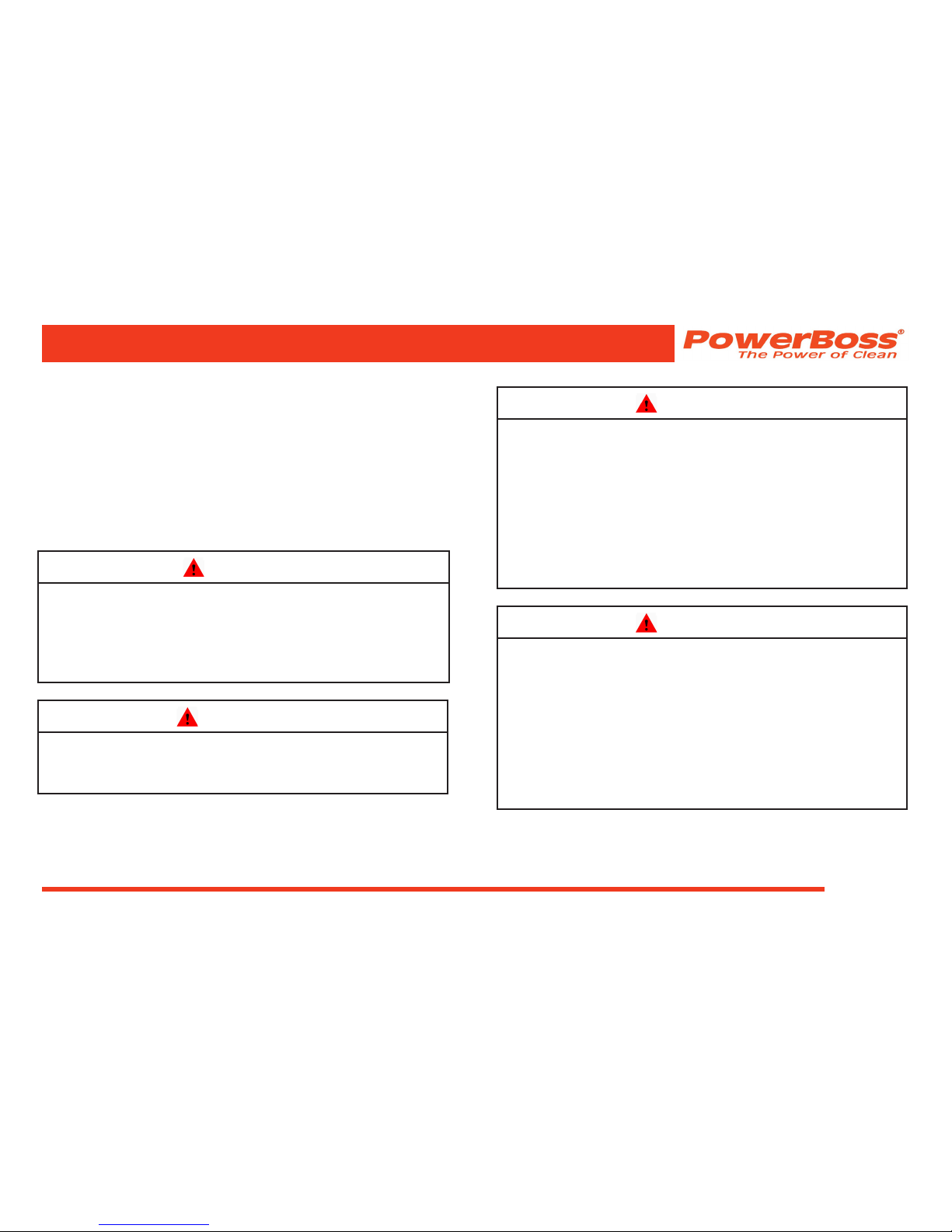
BASIC POWERBOSS® SAFETY
PowerBoss® sweepers should never be operated unless:
1. The operator is trained and authorized to operate
the equipment and,
2. The equipment is functioning correctly.
Malfunctioning equipment should be removed from
service.
DANGER
Keep cigarettes, matches and all other ame sources
away from the sweeper. Gasoline, LP gas and diesel
fuel are highly ammable. Lead acid batteries are
equally dangerous due to the highly explosive
hydrogen gas they emit.
WARNING
Do not operate an LPG powered sweeper when any
component in the fuel system is malfunctioning or
leaking.
WARNING
Before starting the engine, make sure that:
* You have read and understand the User Manual.
* You are securely seated in the operator’s seat.
* The parking brake is engaged.
* The directional control pedal is in neutral.
* The throttle is in idle.
* Hydraulic controls are in the OFF position.
WARNING
During operation:
* Keep your hands and body clear of moving
parts, especially when the hopper or lift arms are
partially or fully raised.
* Make sure others in the area stay clear of the
equipment and moving parts.
* Never attempt to dump debris from a dock or
mezzanine. Dump from ground level only.
SAFETY INFORMATION

Minuteman, International, Inc. Copyright 2011-2015
Atlas Sweeper #4100053UM Rev. B 05/15
Page 22
WARNING
When leaving the sweeper unattended:
* Place the controls in the OFF position.
* Set the parking brake.
* Shut off the engine.
* Remove the key.
WARNING
When servicing or repairing the fuel system:
* Work in a properly ventilated area, do not smoke
or allow an open ame near the fuel system.
* Never bypass safety components unless you are
testing them.
* Never bypass the fuel lter lock, except when
testing them (and always reconnect them after
testing).
* Wear gloves to disconnect the tank coupling.
WARNING
During cleaning and maintenance:
* Always stop the engine and set the parking brake
before servicing.
* Never use detergents or cleansers that are
ammable or combustible.
* Never inate a pneumatic tire without using a
safety cage.
* Do not attempt any impeller adjustment unless
you have shut off the engine. Never place your
hands near the intake hoses or inlet when the
engine is running.
* Always engage the safety arm before servicing the
hopper. Do not rely on the hydraulic cylinder to
keep the hopper raised.
* Never test for hydraulic hose leaks using your
hand or any other part of your body. High pressure
leaks can be very dangerous and should only be
checked using a piece or paper.
SAFETY INFORMATION
Atlas Sweeper #4100053UM Rev. B 05/15
Minuteman, International, Inc. Copyright 2011-2015
Page 23
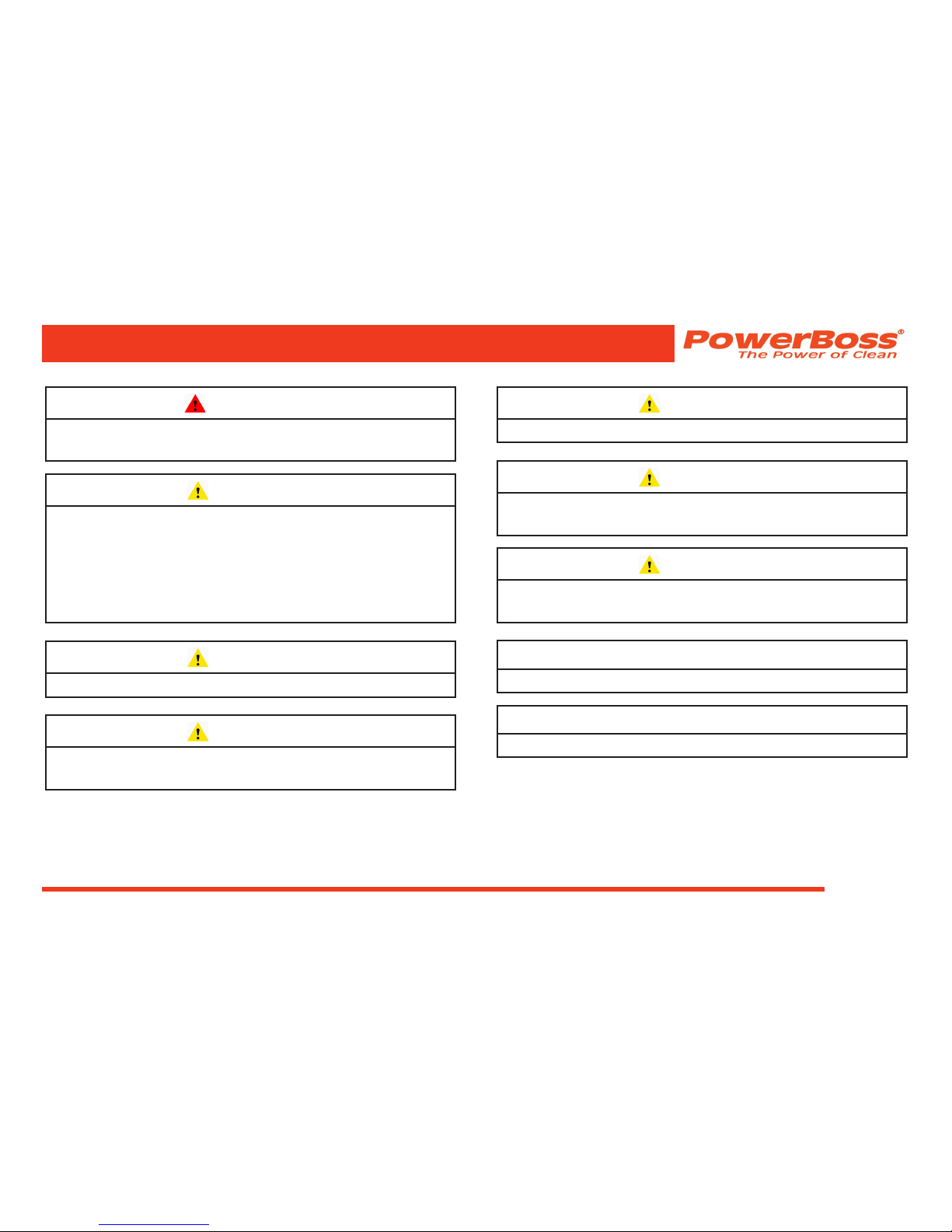
WARNING
Replace any defective safety components before
operating the sweeper.
CAUTION
Do not drive with the hopper in the raised position
except the few feet necessary to position the hopper
over the dumpster or receptacle. Driving with
the hopper raised reduces visibility and creates
conditions for striking over-head objects, throwing
the machine off-balance and other hazards.
CAUTION
Travel slowly on grades.
CAUTION
Place a block or chock behind the wheels when
parking on inclines.
MACHINE OPERATION
CAUTION
Use special care when traveling on wet surfaces.
CAUTION
Observe all proper procedures for operation and
maintenance of the unit, as outlined in this manual.
CAUTION
Remain alert at all times to people and equipment in
and around your area of operation.
ATTENTION!
Never push or tow a machine faster than 6 mph.
ATTENTION!
Engage tow valve before towing or pushing.

Minuteman, International, Inc. Copyright 2011-2015
Atlas Sweeper #4100053UM Rev. B 05/15
Page 24
MACHINE OPERATION
BASIC OPERATING CONTROLS &
INDICATORS
IGNITION SWITCH
The ignition switch located to the right of the steering
column and is used to start and stop the engine.
THROTTLE / GLOW PLUG SWITCH
The LPG and gasoline machines have a three speed
throttle switch with idle, operating and fast selections. The
diesel machine has three position throttle with, glow plug,
idle and operating selections. The throttle is located to the
right of the steering column and adjusts the engine speed.
• The glow plug selection activates the glow plugs.
• The throttle should be in the IDLE position when
starting the engine and immediately before
shutdown.
• The operating position should be used during
operation to ensure proper broom speed and dust
control.
• The fast selection is not recommended for sweeping
due to excessive broom wear. The fast selection is
for traveling from location to location.
LIGHT SWITCH
The light switch, located to the left of the steering column
operates the head lights, tail lights and optional side broom
light.
HORN BUTTON
The horn is activated by pressing the horn button which is
located to the right of the steering column below the throttle
switch.
FUEL LEVEL GAUGE
The gasoline and diesel models are equipped with a fuel
gauge, located to the far left of the steering column and
indicates the amount of fuel remaining in the tank.
HOUR METER
The hour meter, located on the left side of the operator
compartment, records the number of hours the machine
has been operated. The hour meter provides a helpful
guide for performing routine maintenance tasks.
MACHINE OPERATION
 Loading...