

PowerBoss Nautilus, Nautilus CE User Manual

User Manual
Nautilus & Nautilus CE
Rider ScrubberSweeper
Models: Diesel, Gasoline, & LPG
PowerBoss®, Minuteman International, Inc.
A Member of the Hako Group
#988749UM Rev. C 07/15

© 2014-2015 Minuteman International, Inc.
Nautilus Rider Scrubber/Sweeper #988749UM Rev. C 07/15
Page 2
PREFACE
Thank you for your purchase of the new industry standard for scrubber/sweepers. PowerBoss® takes
great pride in offering the most dependable, reliable and best value in industrial power scrubbers and
sweepers. We set the standard.
Our Customer Service Department would like to hear from you. If you see any errors, omissions or
something that needs clarication in this User Manual, please let us know. We are working hard to-
wards continually improving our processes--to benet you, our valued customer.
Please copy the form below, ll out and comment on how you found our manual.
Thank you!
The PowerBoss Team
PREFACE

Nautilus Rider Scrubber/Sweeper #988749UM Rev. C 07/15
© 2014-2015 Minuteman International, Inc.
Page 3
Name: _____________________________________________
Title: _______________________________________________
Company Name: _____________________________________
Address: ____________________________________________
Country: ____________________________________________
Type of equipment or model number: ______________________
Comments: ___________________________________________________________________
_____________________________________________________________________________
_____________________________________________________________________________
Please return to:
Customer Service Manager
PowerBoss®, Minuteman International, Inc.
14N845 U.S. Route 20
Pingree Grove, Illinois 60140 USA
Phone: (800) 323-9420
Email: tech@powerboss.com
PREFACE
© 2014-2015 Minuteman International, Inc.
Nautilus Rider Scrubber/Sweeper #988749UM Rev. C 07/15
Page 4
This is the User Manual for the PowerBoss® Nautilus Rider Scrubber/Sweeper.
This manual covers all Standard Nautilus machine variations beginning July 2015.
We believe this machine will provide excellent service for many years.
However, the best results will be obtained if:
• The machine is operated with reasonable care.
• The machine is maintained regularly per the maintenance schedule provided in this User Manual.
• The machine is maintained with PowerBoss® supplied or equivalent parts.
All right side and left side references to the machine (except for engine) are determined by facing the
direction of forward travel. The front of the engine or engine fan faces the front of the machine. Some
hardware considered to be common or locally available has been omitted from the parts section to make
this manual clear. Be sure to use equivalent hardware when replacement becomes necessary.
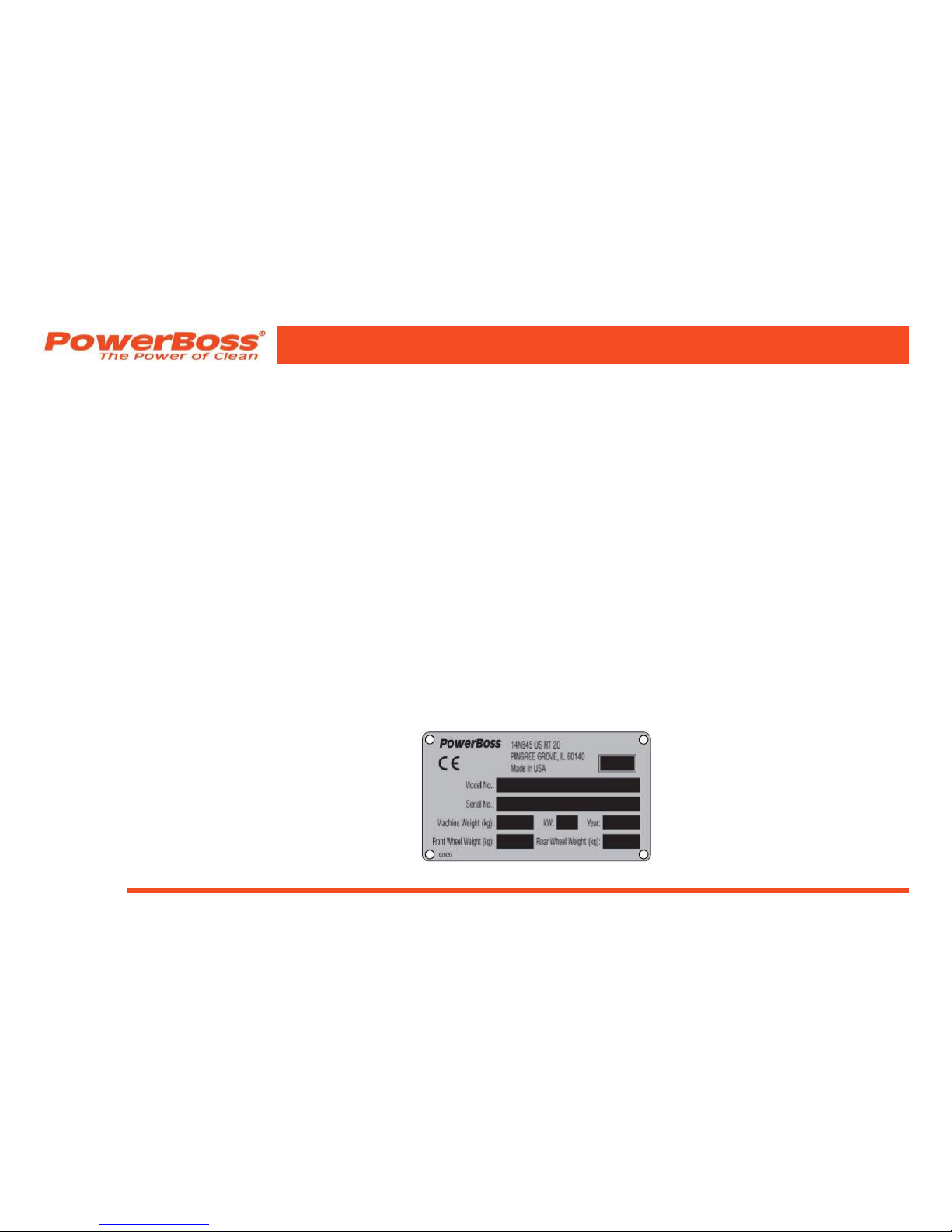
The Model and Serial Number of your machine is shown on the I.D. name plate. This information is
needed when contacting Technical Support or when ordering parts. The I.D. plate is mounted on the left
side wall of the operator seating area.
Example I.D. Plate:
PREFACE

Nautilus Rider Scrubber/Sweeper #988749UM Rev. C 07/15
© 2014-2015 Minuteman International, Inc.
Page 5
Parts may be ordered by phone, fax or e-mail from your local PowerBoss® parts and service center.
Before ordering parts or supplies, be sure to have your machine Model Number and Serial Number
handy. For your convenience Fill out the Machine Data block for future reference.
MACHINE DATA
Fill out at installation
Model Number: ___________________________________
Serial Number: ___________________________________
Engine Serial Number: _____________________________
Sales Rep.: _________________ Date of Install: ________
All information contained in this catalog is current at the time of printing.
Minuteman International, Inc. reserves the right to make changes at any time without notice.
PowerBoss®, Minuteman International, Inc., Copyright 2014-2015, Printed in USA
PREFACE

© 2014-2015 Minuteman International, Inc.
Nautilus Rider Scrubber/Sweeper #988749UM Rev. C 07/15
Page 6
TECHNICAL SPECIFICATIONS
GENERAL MACHINE SPECIFICATIONS
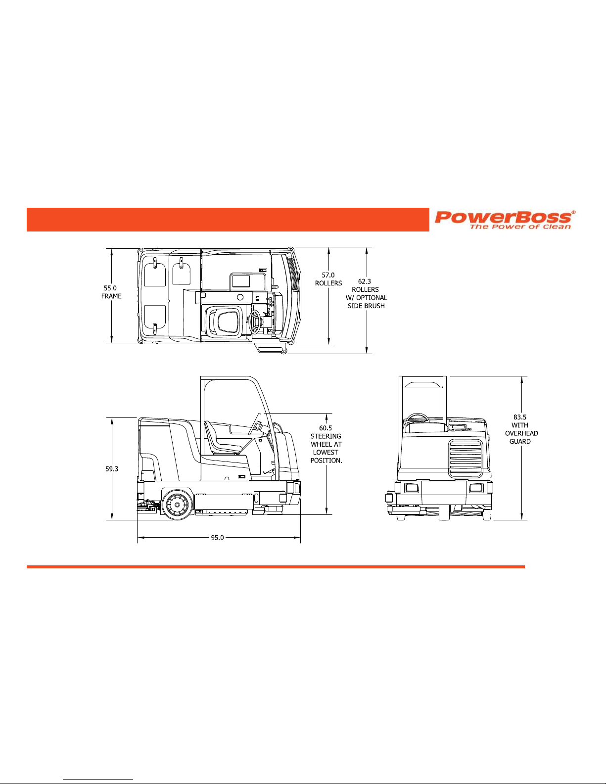
Length:. . . . . . . . . . . . . . . . . . . . . . . . . . . 95.0 in (241 cm)
Width with side scrub brush retracted: . . .60.5 in (153 cm)
Width with side scrub brush extended:. . .65.5 in (166 cm)
Height to lowest steering position:. . . . . . 60.5 in (153 cm)
Height w/overhead guard: . . . . . . . . . . . . 83.5 in (212 cm)
Wheelbase: . . . . . . . . . . . . . . . . . . . . . . . 47.75 in (121 cm)
Front tires (molded): . . . . . . . . . . . . . . . .16 in x 6 in
. . . . . . . . . . . . . . . .(40 cm x 15 cm)
Rear tires (press on):. . . . . . . . . . . . . . . .18 in x 5 in
. . . . . . . . . . . . . . . .(45 cm x 12 cm)
Aisle width U-turn: . . . . . . . . . . . . . . . . . .8 ft - 11.7 in (274 cm)
Weight (Diesel engine) . . . . . . . . . . . . . .4,047 lb (1836 kg)
Weight (Gas & LPG engines) . . . . . . . . .4,027 lb (1826 kg)
Maximum forward speed: . . . . . . . . . . . .7.7 mph (12,4 km/h)
Maximum reverse speed: . . . . . . . . . . . .4.0 mph (6,4 km/h)
Maximum climb angle (Traveling):. . . . . .10 deg. (17% grade)
Maximum climb angle (Scrubbing): . . . . .8 deg. (14% grade)
SCRUBBING SYSTEM
Cleaning path (main brushes) . . . . . . . . . 45 in (114 cm)
Cleaning path (w/optional side brush) . . . . 60 in (152 cm)
Main brush diameter:. . . . . . . . . . . . . . . . . 12 in (30 cm)
Main brush length:. . . . . . . . . . . . . . . . . . . 45 in (114 cm)
Main brush speed:. . . . . . . . . . . . . . . . . . . 425 RPM
Main brush force:. . . . . . . . . . . . . . . . . . . . 200 lb - 400 lb
. . . . . . . . . . . . . . . . . . . . (90 kg - 181 kg)
Side scrub brush diameter: . . . . . . . . . . . . 16 in (40 cm)
Side scrub brush speed: . . . . . . . . . . . . . . 200 RPM
Solution Tank capacity: . . . . . . . . . . . . . . . 105 gal (397 L)
Recovery Tank capacity: . . . . . . . . . . . . . . 105 gal (397 L)
Demister chamber capacity: . . . . . . . . . . . 17 gal (64 L)
(2)Debris trays, total capacity: . . . . . . . . . . 2.1 ft³ (0,06 m³)
Vacuum fan speed: . . . . . . . . . . . . . . . . . . 11,500 RPM
Vacuum water lift: . . . . . . . . . . . . . . . . . . . 35 in (88 cm)
TECHNICAL SPECIFICATIONS
Model: Nautilus Rider Scrubber/Sweeper Nautilus CE Rider Scrubber/Sweeper
Model No.: PB45DSL(Diesel), PB45GAS(Gas), PB45LPG(LPG) PB45DSLCE(Diesel), PB45LPGCE(LPG)
Nautilus Rider Scrubber/Sweeper #988749UM Rev. C 07/15
© 2014-2015 Minuteman International, Inc.
Page 7
TECHNICAL SPECIFICATIONS
dimensions shown in inches (cm)
(139,7 cm)
(144,7 cm)
(158,2 cm)
(153,6 cm)
(212,0 cm)
(150,6 cm)
(241,3 cm)

© 2014-2015 Minuteman International, Inc.
Nautilus Rider Scrubber/Sweeper #988749UM Rev. C 07/15
Page 8
TABLE OF CONTENTS
PREFACE. . . . . . . . . . . . . . . . . . . . . . . . . . . . . . . . . . 2
TECHNICAL SPECIFICATIONS . . . . . . . . . . . . . . . 6
GENERAL MACHINE SPECIFICATIONS . . . . . . . . . . 6
SCRUBBING SYSTEM . . . . . . . . . . . . . . . . . . . . . . . . . 6
FEATURES . . . . . . . . . . . . . . . . . . . . . . . . . . . . . . . . 12
AIR-MOVING SYSTEM . . . . . . . . . . . . . . . . . . . . . . . . . 12
ERGONOMICS SYSTEM . . . . . . . . . . . . . . . . . . . . . . . 12
HYDRAULIC SYSTEM . . . . . . . . . . . . . . . . . . . . . . . . . 12
DRIVE-TRAIN SYSTEM . . . . . . . . . . . . . . . . . . . . . . . . 12
CHASSIS SYSTEM . . . . . . . . . . . . . . . . . . . . . . . . . . . . 12
ENVIRONMENTAL FRIENDLY FEATURES . . . . . . . . 12
LOWER EMISSIONS . . . . . . . . . . . . . . . . . . . . . . . . 12
SAFER WORK ENVIRONMENT. . . . . . . . . . . . . . . 12
SAFETY INFORMATION . . . . . . . . . . . . . . . . . . . . . 13
IMPORTANT SAFETY INSTRUCTIONS . . . . . . . . . . . 13
FOR SAFETY DURING OPERATION . . . . . . . . . . . . . 13
SAFETY WHEN SERVICING OR MAINTAINING . . . . 14
SAFETY SYMBOLS . . . . . . . . . . . . . . . . . . . . . . . . . . . . 14
SAFETY DECALS . . . . . . . . . . . . . . . . . . . . . . . . . . . . . 15
BASIC POWERBOSS® SAFETY . . . . . . . . . . . . . . 17
MACHINE OPERATION . . . . . . . . . . . . . . . . . . . . . . 20
OPERATING CONTROLS AND INDICATORS . . . . . . 20
IGNITION SWITCH . . . . . . . . . . . . . . . . . . . . . . . . . . . . 20
THROTTLE / GLOW PLUG SWITCH. . . . . . . . . . . . . . 20
MURPHY SWITCH. . . . . . . . . . . . . . . . . . . . . . . . . . . . . 20
LIGHT SWITCH . . . . . . . . . . . . . . . . . . . . . . . . . . . . . . . 20
HORN BUTTON. . . . . . . . . . . . . . . . . . . . . . . . . . . . . . . 20
FUEL LEVEL GAUGE . . . . . . . . . . . . . . . . . . . . . . . . . . 20
CIRCUIT BREAKER . . . . . . . . . . . . . . . . . . . . . . . . . . . 22
IDLE BUTTON . . . . . . . . . . . . . . . . . . . . . . . . . . . . . . . . 22
HOUR METER . . . . . . . . . . . . . . . . . . . . . . . . . . . . . . . . 22
INDICATOR LIGHTS . . . . . . . . . . . . . . . . . . . . . . . . . . . 22
CHECK ENGINE INDICATOR. . . . . . . . . . . . . . . . . 22
ENGINE OIL PRESSURE INDICATOR . . . . . . . . . 22
ENGINE COOLANT TEMPERATURE INDICATOR 22
RECOVERY TANK FULL INDICATOR . . . . . . . . . . 22
SOLUTION TANK EMPTY INDICATOR . . . . . . . . . 22
DIRECTIONAL CONTROL PEDAL . . . . . . . . . . . . . . . . 23
BRAKE / PARKING BRAKE . . . . . . . . . . . . . . . . . . . . . 23
TILT STEERING LEVER . . . . . . . . . . . . . . . . . . . . . . . . 23
SEAT ADJUSTMENT. . . . . . . . . . . . . . . . . . . . . . . . . . . 23
TABLE OF CONTENTS

Nautilus Rider Scrubber/Sweeper #988749UM Rev. C 07/15
© 2014-2015 Minuteman International, Inc.
Page 9
INSTRUMENT PANEL CONTROL SWITCHES . . . 24
GREEN “ONE-TOUCH” SWITCH . . . . . . . . . . . . . . . . . 26
SQUEEGEE SWITCH . . . . . . . . . . . . . . . . . . . . . . . . . . 26
SCRUB BRUSH SWITCH . . . . . . . . . . . . . . . . . . . . . . . 26
SIDE SCRUB BRUSH SWITCH - OPTION . . . . . . . . . 26
MAIN BRUSH SCRUB PRESSURE KNOB . . . . . . . . . 27
SIDE BRUSH SCRUB PRESSURE . . . . . . . . . . . . . . . 27
SOLUTION CONTROL KNOB . . . . . . . . . . . . . . . . . . . 27
BASIC SCRUBBING/FILLING/EMPTYING
INFORMATION . . . . . . . . . . . . . . . . . . . . . . . . . . . . . 28
CHOOSING THE CORRECT TYPE OF BRUSH. . . . . 28
FILLING THE SOLUTION TANK. . . . . . . . . . . . . . . . . . 29
FILLING THE SOLUTION TANK. . . . . . . . . . . . . . . . . . 30
NORMAL SCRUBBING . . . . . . . . . . . . . . . . . . . . . . . . . 31
DOUBLE SCRUBBING . . . . . . . . . . . . . . . . . . . . . . . . . 33
STOP SCRUBBING . . . . . . . . . . . . . . . . . . . . . . . . . . . . 34
WATER PICK UP MODE (SQUEEGEE ONLY) . . . . . . 35
STOP WATER PICK UP . . . . . . . . . . . . . . . . . . . . . . . . 35
DRAINING/CLEANING THE RECOVERY TANK . . . . 36
EMPTYING/CLEANING THE DEBRIS HOPPER . . . . 38
DRAINING THE SOLUTION TANK . . . . . . . . . . . . . . . 40
OPERATING PROCEDURES. . . . . . . . . . . . . . . . . . 41
PRE-OPERATION CHECKS. . . . . . . . . . . . . . . . . . . . . 41
STARTING . . . . . . . . . . . . . . . . . . . . . . . . . . . . . . . . . . . 41
DRIVING. . . . . . . . . . . . . . . . . . . . . . . . . . . . . . . . . . . . . 42
SLOWING AND STOPPING . . . . . . . . . . . . . . . . . . 42
INCLINES OR SLIPPERY SURFACES . . . . . . . . . 42
STOP THE MACHINE . . . . . . . . . . . . . . . . . . . . . . . . . . 42
TRANSPORTING THE MACHINE . . . . . . . . . . . . . . . . 43
USING A TRAILER OR TRANSPORT VEHICLE 43
PUSHING OR TOWING THE MACHINE . . . . . . . . 43
OPTIONS . . . . . . . . . . . . . . . . . . . . . . . . . . . . . . . . . . 44
CHEMICAL METERING . . . . . . . . . . . . . . . . . . . . . . . . 44
AUTO-FILL . . . . . . . . . . . . . . . . . . . . . . . . . . . . . . . . . . . 45
NEUTRAL START SENSOR (CE). . . . . . . . . . . . . . . . . 45
OPERATOR SEAT SENSOR (CE) . . . . . . . . . . . . . . . . 45
KEY LOCKED ENTRY DOORS (CE) . . . . . . . . . . . . . . 45
SPRAY AND VACUUM WAND . . . . . . . . . . . . . . . . . . . 46
TABLE OF CONTENTS

© 2014-2015 Minuteman International, Inc.
Nautilus Rider Scrubber/Sweeper #988749UM Rev. C 07/15
Page 10
PREVENTATIVE MAINTENANCE. . . . . . . . . . . . . . 48
SCHEDULED MAINTENANCE CHART . . . . . . . . . . . . 49
PREVENTATIVE MAINTENANCE INSTRUCTIONS 52
ENGINE . . . . . . . . . . . . . . . . . . . . . . . . . . . . . . . . . . 52
AIR INTAKE SYSTEM . . . . . . . . . . . . . . . . . . . . . . . 53
ELECTRICAL SYSTEM . . . . . . . . . . . . . . . . . . . . . 55
Battery Cleaning. . . . . . . . . . . . . . . . . . . . . . . . . . 55
Circuit Breaker . . . . . . . . . . . . . . . . . . . . . . . . . . . 56
Fuses . . . . . . . . . . . . . . . . . . . . . . . . . . . . . . . . . . 56
FUEL SYSTEM . . . . . . . . . . . . . . . . . . . . . . . . . . . . 57
COOLANT SYSTEM . . . . . . . . . . . . . . . . . . . . . . . . 58
LUBRICATION . . . . . . . . . . . . . . . . . . . . . . . . . . . . . 58
LUBRICATION POINTS . . . . . . . . . . . . . . . . . . . . . 59
Steering Fork Bearings . . . . . . . . . . . . . . . . . . . . 59
Rear Wheel Bearings. . . . . . . . . . . . . . . . . . . . . . 59
Squeegee Caster Bearings . . . . . . . . . . . . . . . . . 59
Scrub Head Lift Arm Bearings . . . . . . . . . . . . . . . 59
LATCHES & HINGES . . . . . . . . . . . . . . . . . . . . . . . . 60
STATIC STRAP . . . . . . . . . . . . . . . . . . . . . . . . . . . . 60
HYDRAULIC SYSTEM. . . . . . . . . . . . . . . . . . . . . . . 61
Hydraulic Fluid Reservoir. . . . . . . . . . . . . . . . . . . 61
Hydraulic Fluid Viscosity Specications . . . . . . . . 62
Changing the Hydraulic Fluid . . . . . . . . . . . . . . . . 62
Hydraulic Fluid Filter . . . . . . . . . . . . . . . . . . . . . . 63
Changing The Hydraulic Fluid Filter. . . . . . . . . . . 63
Maintaining Hydraulic Oil Cooler Efciency . . . . . 63
Adjusting the Propulsion Pump Neutral Setting 64
Drive Motor. . . . . . . . . . . . . . . . . . . . . . . . . . . . . . 65
SCRUBBING COMPONENTS . . . . . . . . . . . . . . . . 66
Scrub Brushes . . . . . . . . . . . . . . . . . . . . . . . . . . . 66
Replace or Rotate the Cylindrical Scrub Brushes 67
Checking the Scrub Brush Pattern . . . . . . . . . . . . 69
Adjusting the Scrub Brush Pattern (Taper). . . . . . 70
Adjusting the Scrub Brush Pattern (Equal width) 71
SIDE SCRUB BRUSH (OPTION) . . . . . . . . . . . . . . 72
Replacing the Side Scrub Brush . . . . . . . . . . . . . 72
SQUEEGEES . . . . . . . . . . . . . . . . . . . . . . . . . . . . . . 73
Lowering Squeegee for Adjustment (engine off) 73
Checking the Rear Squeegee Blade Flare. . . . . . 73
Adjusting the Rear Squeegee Blade Flare. . . . . . 74
Leveling the Rear Squeegee . . . . . . . . . . . . . . . . 75
Turning or Replacing the Rear Squeegee Blades 76
TABLE OF CONTENTS

Nautilus Rider Scrubber/Sweeper #988749UM Rev. C 07/15
© 2014-2015 Minuteman International, Inc.
Page 11
SIDE SQUEEGEES . . . . . . . . . . . . . . . . . . . . . . . . . 78
Replacing Side Squeegee Blades . . . . . . . . . . . . 78
SIDE SCRUB BRUSH SQUEEGEE (OPTION) 79
Replacing Side Scrub Brush Squeegee Blade 79
SKIRTS AND SEALS . . . . . . . . . . . . . . . . . . . . . . . . 80
Scrub Deck Front Skirt. . . . . . . . . . . . . . . . . . . . . 80
Scrub Deck Rear Skirt . . . . . . . . . . . . . . . . . . . . . 80
Hopper Vacuum Seal . . . . . . . . . . . . . . . . . . . . . 81
Cover Seals . . . . . . . . . . . . . . . . . . . . . . . . . . . . . 81
BRAKES . . . . . . . . . . . . . . . . . . . . . . . . . . . . . . . . . . 82
Service Brakes. . . . . . . . . . . . . . . . . . . . . . . . . . . 82
Parking Brake . . . . . . . . . . . . . . . . . . . . . . . . . . . . 82
Adjusting the Brake System. . . . . . . . . . . . . . . . . 82
TIRES . . . . . . . . . . . . . . . . . . . . . . . . . . . . . . . . . . . . 83
Changing Solid Tires . . . . . . . . . . . . . . . . . . . . . . 83
Front Tires . . . . . . . . . . . . . . . . . . . . . . . . . . . . . . 83
Rear Tires. . . . . . . . . . . . . . . . . . . . . . . . . . . . . . . 83
SENSING SWITCHES. . . . . . . . . . . . . . . . . . . . . . . 84
Adjusting the Neutral Sensing Switch . . . . . . . . . 84
Neutral Sensing Switch Adjustment: . . . . . . . . . . 84
Adjusting the Nautilus Reverse Sensing Switch 85
Nautilus Reverse Sensing Switch Adjustment: 86
COVERS . . . . . . . . . . . . . . . . . . . . . . . . . . . . . . . . . . 87
Seat Mount Adjustment: . . . . . . . . . . . . . . . . . . . . 87
SOLUTION DELIVERY BAR & FILTER SYSTEM 88
Solution Delivery Bar . . . . . . . . . . . . . . . . . . . . . . 88
Solution Filter . . . . . . . . . . . . . . . . . . . . . . . . . . . . 88
TROUBLESHOOTING . . . . . . . . . . . . . . . . . . . . . . . 89
CE DECLARATION OF CONFORMITY . . . . . . . . . 96
WARRANTY. . . . . . . . . . . . . . . . . . . . . . . . . . . . . . . . 98
TABLE OF CONTENTS

© 2014-2015 Minuteman International, Inc.
Nautilus Rider Scrubber/Sweeper #988749UM Rev. C 07/15
Page 12
FEATURES
FEATURES
AIR-MOVING SYSTEM
• Internal sound insulation on vacuum impeller
ERGONOMICS SYSTEM
• Roomy, open operator compartment for extra comfort
• Toe operated parking brake
• Adjustable, high-back seat
• Power steering and tilt steering wheel
• Unparalleled maintenance accessibility, hinged sides
and covers require no tools.
HYDRAULIC SYSTEM
• Protection for both auxiliary and propulsion pumps
using separate 100 mesh suction strainer
• Hydraulic reservoir equipped with site gauge and dip
stick for uid level check and replacement
• Hydraulic lter equipped with color coded pressure
gauge to indicate lter replacement
DRIVE-TRAIN SYSTEM
• Industrial liquid-cooled engine
• Heavy-duty radiator & Tri-phase air cleaner
• Hydraulics protection package
• 4-Core Radiator
CHASSIS SYSTEM
• Massive One-Piece, unitized 7ga, 0.188 in (0,48 cm)
thick steel frame
• Soft-ride tires
ENVIRONMENTAL FRIENDLY FEATURES
LOWER EMISSIONS
All gas and LP engines meet EPA and CARB specications
and have catalyst mufers. Diesel operation is available,
bio-diesel fuel can be used in Kubota engines.
SAFER WORK ENVIRONMENT
Orange machines are highly visible to others in the
workplace, simple controls reduce operator error. Machine is
equipped with a horn and an effective braking system. Some
Safety Options available are: Overhead Guard, Backup
Alarm, Safety Lights, and Fire Extinguisher.

Nautilus Rider Scrubber/Sweeper #988749UM Rev. C 07/15
© 2014-2015 Minuteman International, Inc.
Page 13
SAFETY INFORMATION
IMPORTANT SAFETY INSTRUCTIONS
Operators must read and understand this manual before
operating or maintaining this machine.
Do not operate this machine in ammable or explosive
areas.
This machine is designed solely for removing dirt, dust and
debris in an outdoor or indoor environment. PowerBoss does
not recommend using this machine in any other capacity.
The following information indicate a potential hazard to the
operator and equipment. Read this manual carefully and
be aware when these conditions can exist. Take necessary
steps to locate all safety devices on the machine and train
the personnel operating the machine. Report any machine
damage or faulty operation immediately. Do not use machine
if it is not in proper operating condition.
FOR SAFETY DURING OPERATION
Keep hands and feet clear of moving parts while machine is
in operation.
Make sure all safety devices are in place and operate
properly. All covers, doors and latches must be in place,
closed and fastened before use.
During operation, attention should be paid to other persons
in the work area and especially if small children are present.
Components can cause an explosion when operated near
explosive materials or vapor. Do not operate this machine
near ammable materials such as solvents, thinners, fuels,
grain dust, etc.
Store or park this machine on a level surface only. To prevent
unauthorized use, machine should be stored or parked with
the parking brake set and the key removed.
This machine is designed for level operation only. Do not
operate on ramps or inclines greater than 14 degrees (24.9%
grade).
This machine is not suitable for picking up hazardous dusts.
Use caution when moving this machine into areas that are
below freezing temperatures.
SAFETY INFORMATION
© 2014-2015 Minuteman International, Inc.
Nautilus Rider Scrubber/Sweeper #988749UM Rev. C 07/15
Page 14
SAFETY INFORMATION
SAFETY WHEN SERVICING OR MAINTAINING
THE MACHINE
Stop on level surface, set parking brake and turn off
machine.
Disconnect the power to the machine when servicing.
Avoid moving parts. Do not wear loose jackets, shirts, or
sleeves when working on machine.
Avoid contact with battery acid. Battery acid can cause
burns. When working on or around batteries, wear protective
clothing and safety glasses. Remove metal jewelry. Do not
lay tools or metal objects on top of battery.
Authorized personnel must perform repairs and
maintenance. Use PowerBoss supplied replacement parts.
SAFETY SYMBOLS
Five symbols are used throughout this manual to emphasize
various levels of safety information. These symbols and the
meaning of each are listed below.
DANGER
To warn of immediate hazards which will result in
severe personal injury or death
WARNING
To warn of hazards or unsafe practices which could
result in severe personal injury or death.
CAUTION
To warn of hazards or unsafe practices which could
result in minor personal injury.
ATTENTION!
To warn of practices which could result in extensive
equipment damage.
NOTE: To direct your attention to important equipment
information or special instructions for
preventing damage to equipment
Symbols at the top of the list are the strongest warnings.
However, all symbols represent important information which
should be observed to protect you and others from harm and
injury, and to prevent damage to the equipment.
Nautilus Rider Scrubber/Sweeper #988749UM Rev. C 07/15
© 2014-2015 Minuteman International, Inc.
Page 15
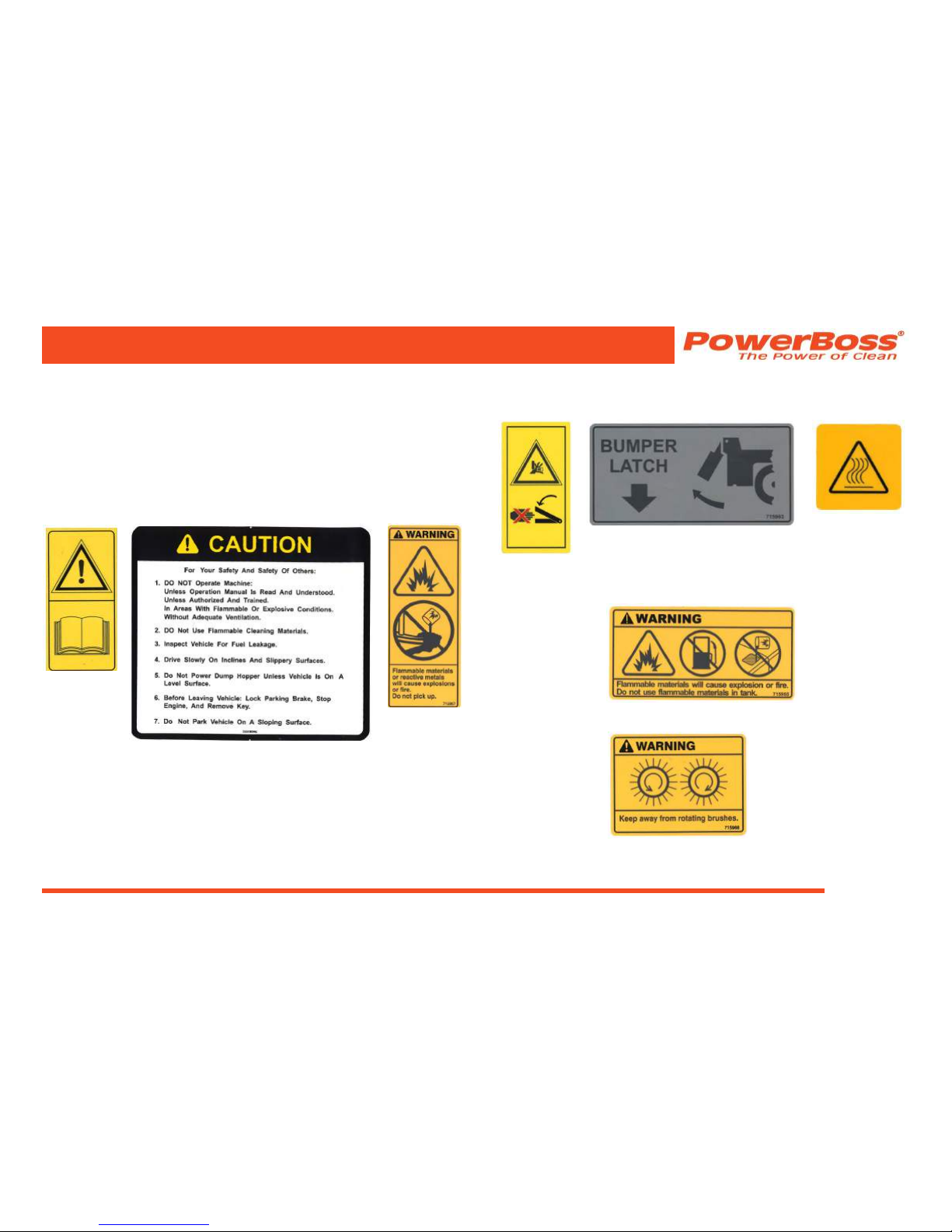
SAFETY DECALS
Decals directly attached to various parts of the unit are highly
visible safety reminders which should be read and observed.
Make sure the decals are replaced if they become illegible or
damaged.
Safety decals located in the Operator compartment area:
#3342264: #3301854: #715967:
(Read
Manual)
SAFETY INFORMATION
Safety decals located on the outside of the machine:
#3342650 #715963 #3342978
(Hot Surface)
(Pinch Point)
Safety Decal on inside of Recovery Tank Cover:
#715965
Safety decals on inside of Main Brush Side Doors:
#715968
© 2014-2015 Minuteman International, Inc.
Nautilus Rider Scrubber/Sweeper #988749UM Rev. C 07/15
Page 16
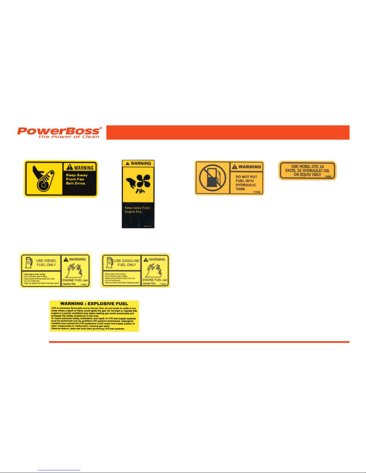
Safety decals located in the Engine compartment area:
#3301730: #3301733:
Safety decals located in Fuel Tank area:
#715953: #715949:
#3342971:
SAFETY INFORMATION
Safety decals located in Hydraulic Reservoir area:
#715966: #715023:
Nautilus Rider Scrubber/Sweeper #988749UM Rev. C 07/15
© 2014-2015 Minuteman International, Inc.
Page 17
SAFETY INFORMATION
BASIC POWERBOSS® SAFETY
PowerBoss® scrubbers should never be operated unless:
1. The operator is trained and authorized to operate
the equipment and,
2. The equipment is functioning correctly.
Malfunctioning equipment should be removed from
service.
DANGER
Keep cigarettes, matches and all other ame sources
away from the machine. Gasoline, LP Gas, and diesel
fuels are highly ammable. Lead acid batteries
are equally dangerous due to the highly explosive
hydrogen gas they emit.
WARNING
Do not operate an LPG powered scrubber when any
component in the fuel system is malfunctioning or
leaking.
WARNING
Before starting the engine, make sure that:
* You have read and understood this User Manual
* You are securely seated in the operator’s seat.
* The parking brake is engaged.
* The directional control pedal is in neutral.
* The throttle is in idle.
* Hydraulic controls are in the OFF position.
WARNING
During operation:
* Keep your hands and body clear of moving parts,
especially when the bumper is partially or fully
raised.
* Make sure others in the area stay clear of the
machine, equipment, and moving parts.

© 2014-2015 Minuteman International, Inc.
Nautilus Rider Scrubber/Sweeper #988749UM Rev. C 07/15
Page 18
SAFETY INFORMATION
WARNING
When leaving the scrubber unattended:
* Place the controls in the OFF position.
* Set the parking brake.
* Shut off the engine.
* Remove the key.
WARNING
When servicing or repairing the fuel system:
* Work in a properly ventilated area, do not smoke or
allow an open ame near the fuel system.
* Never bypass safety components unless you are
testing them.
* Never bypass the fuel lter lock, except when
testing them (and always reconnect them after
testing).
* Wear gloves to disconnect the tank coupling.
WARNING
During cleaning and maintenance:
* Always stop the engine and set the parking brake
before servicing.
* Never use detergents or cleansers that are
ammable or combustible.
* Never inate a pneumatic tire without using a safety
gage.
* Do not attempt any impeller adjustment unless you
have shut off the engine. Never place your hands
near the intake hoses or inlet when the engine is
running.
* Always engage the bumper safety arm before
servicing the hopper. Do not rely on the gas struts to
keep the bumper raised.
* Never test for hydraulic hose leaks using your hand
or any other part of your body. High pressure leaks
can be very dangerous and should only be checked
using a piece or paper.

Nautilus Rider Scrubber/Sweeper #988749UM Rev. C 07/15
© 2014-2015 Minuteman International, Inc.
Page 19
WARNING
Replace any defective safety components before
operating the scrubber.
CAUTION
Do not drive with the bumper in the raised position.
Driving with the bumper raised increases the risk of
damaging the bumper and other hazards.
CAUTION
Travel slowly on grades.
CAUTION
Place a block or chock behind the wheels when
parking on inclines.
CAUTION
Use special care when traveling on wet surfaces.
CAUTION
Observe all proper procedures for operation and
maintenance of the unit, as outlined in this manual.
CAUTION
Remain alert at all times to people and equipment in
and around your area of operation.
ATTENTION!
Never push or tow this machine faster than 1 mph (1,6
km/h).
ATTENTION!
Engage tow valve before towing or pushing.
SAFETY INFORMATION
© 2014-2015 Minuteman International, Inc.
Nautilus Rider Scrubber/Sweeper #988749UM Rev. C 07/15
Page 20
MACHINE OPERATION
OPERATING CONTROLS AND INDICATORS
The right dark gray portion of the instrument panel contains
the engine function switches and indicators.
The left light gray portion of the instrument panel contains
the scrubbing function switches and indicators.
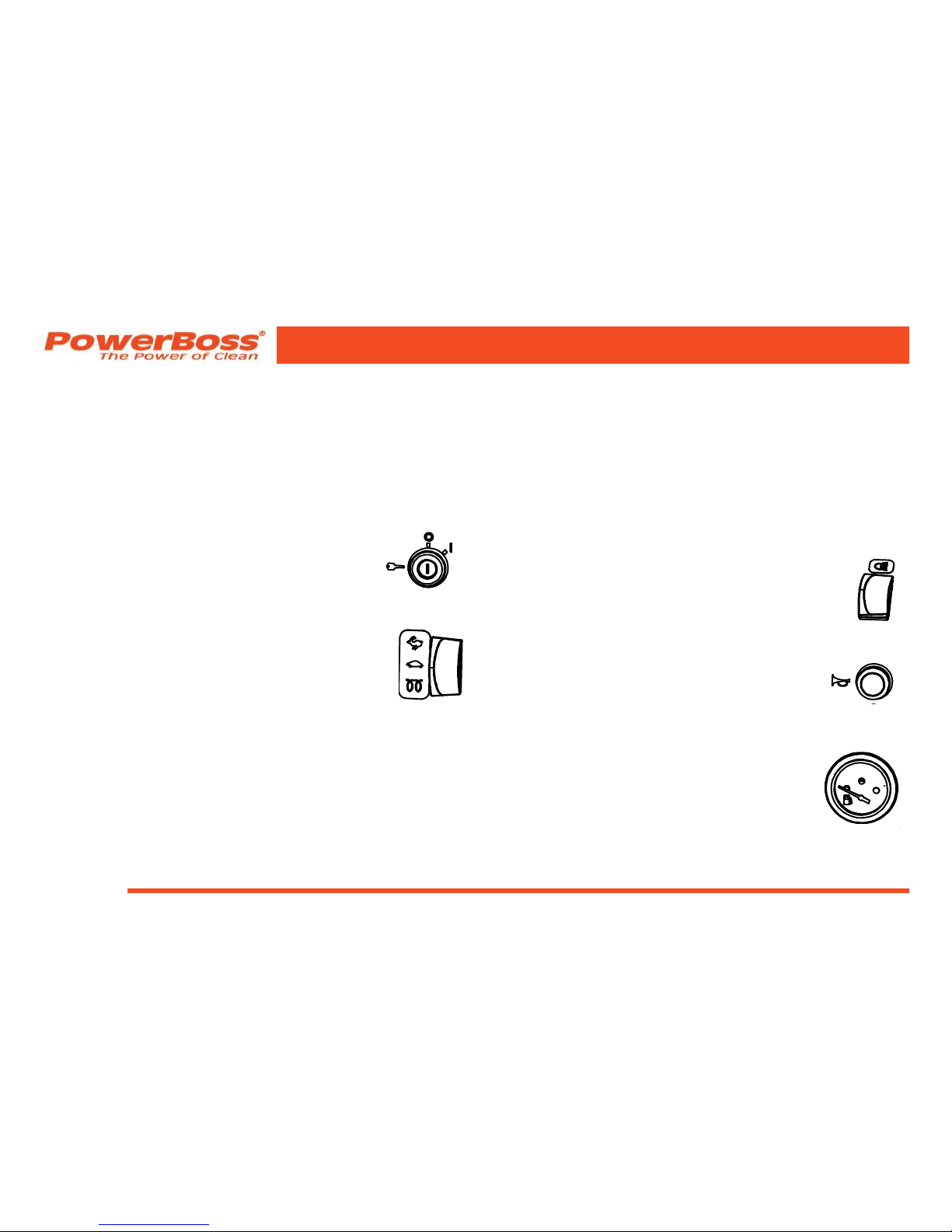
IGNITION SWITCH
The ignition switch is located to the right of the
steering column and is used to start and stop the
engine.
THROTTLE / GLOW PLUG SWITCH
The LPG and gasoline machines have a two speed
throttle switch with idle, operating selection. The
diesel machine has three position throttle with, glow
plug, idle and operating selections. The throttle
is located to the right of the steering column and
adjusts the engine speed.
• The glow plug selection activates the glow plugs.
• The throttle should be in the IDLE position when
starting the engine and immediately before shutdown.
• The operating position should be used during
operation to ensure proper brush speed.
MURPHY SWITCH
Only on the Diesel machines, the Murphy switch is a
automatic diesel shutdown that occurs if the oil pressure is
too low, below 5 psi (34 kPa), and/or the water temperature
is too high, above 200°F (93.3°C). To restart the engine,
press and hold the Murphy switch while turning the ignition
switch. This will action will reset and clear the error code.
Auto shutdown will continue if the oil pressure remains low or
the water temperature is to high.
LIGHT SWITCH
The light switch is located on the left side of the
operator compartment. It operates the head lights
and tail lights.
HORN BUTTON
The horn is activated by pressing the horn button
which is located to the right of the steering
column below the throttle switch.
FUEL LEVEL GAUGE
The gasoline and diesel models are equipped
with a fuel gauge. The gauge is located in the
upper left of the steering column. This gauge
indicates the amount of fuel remaining in the tank.
LPG machines do not have this gauge.
MACHINE OPERATION
Nautilus Rider Scrubber/Sweeper #988749UM Rev. C 07/15
© 2014-2015 Minuteman International, Inc.
Page 21
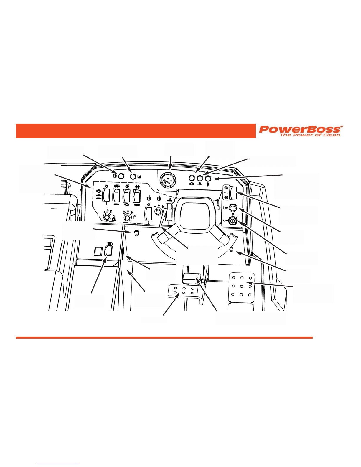
MACHINE OPERATION
TILT
STEERING
ADJUSTMENT
IGNITION
SWITCH
DIRECTIONAL
CONTROL
PEDAL
THROTTLE /
GLOW PLUG
SWITCH
HOUR
METER
BRAKE
HORN
BUTTON
FUEL
GAUGE
RECOVERY
TANK FULL
SOLUTION
TANK EMPTY
LIGHT
SWITCH
CHECK
ENGINE
LIGHT
ENGINE OIL
PRESSURE LIGHT
ENGINE
COOLANT
TEMPERATURE
LIGHT
PARKING BRAKE LOCK
AND RELEASE
CIRCUIT
BREAKER
MURPHY
SWITCH
CONTROL
SWITCH
DETAIL SEE
PAGE 25
IDLE
BUTTON

© 2014-2015 Minuteman International, Inc.
Nautilus Rider Scrubber/Sweeper #988749UM Rev. C 07/15
Page 22
MACHINE OPERATION
CIRCUIT BREAKER
The Circuit Breaker is located on the lower left wall
of the operator compartment. To reset the Circuit
Breaker press the breaker button in until breaker
stays in position.
IDLE BUTTON
The Idle Button is located on the lower right wall
of the operator compartment.When the squeegee
is the down position and this button is pressed,
it will lower the engine RPM to idle. This allows
the operator to turn off the engine and keep the
squeegee on the ground for adjustments.
HOUR METER
The hour meter, located on the left side of the operator
compartment. This meter records the number of hours the
machine has been operated. The hour meter provides a
helpful guide for performing routine maintenance tasks,
located in the Maintenance Section of this manual.
INDICATOR LIGHTS
CHECK ENGINE INDICATOR
The check engine light will illuminate if a problem is
detected. The engine will be automatically shut off.
ENGINE OIL PRESSURE INDICATOR
The engine oil pressure light will illuminate if the oil pressure
drops below 7 psi (48 kPa) indicating a problem which
may result in damage to the engine. The engine will be
automatically shut off.
ENGINE COOLANT TEMPERATURE INDICATOR
The engine coolant temperature light will illuminate if the
engine coolant temperature raises above 220°F (104.4°C).
This indicates an overheated engine. The engine will be
automatically shut off.
RECOVERY TANK FULL INDICATOR
When the recovery tank is nearly full the red “full recovery
tank” indicator lamp on the instrument panel will begin
to blink on and off. When the lamp stops blinking and
remains illuminated the tank is full. A few seconds later the
scrubbing and squeegee systems automatically shut off and
all components are raised to their stored positions. The
vacuum fan will continue to operate for a short time.
SOLUTION TANK EMPTY INDICATOR
When the solution tank is nearly empty a red indicator lamp
on the instrument panel will blink on and off. When the
lamp stops blinking and remains illuminated there is solution
remaining for approximately 10 minutes of scrubbing time.

Nautilus Rider Scrubber/Sweeper #988749UM Rev. C 07/15
© 2014-2015 Minuteman International, Inc.
Page 23
DIRECTIONAL CONTROL PEDAL
The directional control pedal controls the speed and direction
of the machine. It is also used for slowing the machine or
stopping.
• To propel the machine forward, apply pressure to the
front (top part) of the pedal, increasing pressure to
increase speed.
• To propel the machine backward, apply pressure to
the rear (lower part) of the pedal.
• To slow or stop the machine, move the foot pedal into
neutral (release pressure on the pedal).
• For emergency stops, move the foot pedal past
neutral and into the opposite position.
BRAKE / PARKING BRAKE
The mechanical drum brakes on the two rear wheels are
operated by pressing on the brake pedal. To engage the
parking brake push on the brake pedal then depress the
upper brake lock to set the parking brake. To release the
parking brake depress the brake pedal.
TILT STEERING LEVER
The steering wheel can be adjusted to provide the most
comfortable position for the operator. To adjust the steering
wheel loosen lever knob on the left side of the steering
column, position the steering wheel and tighten the lever
knob.
SEAT ADJUSTMENT
The drivers seat is adjustable to provide the most
comfortable position for the operator. The adjustment lever
is at the bottom front of the seat. While sitting in the seat,
push the lever to the right and pull forward or push back on
the seat. Release the lever when the seat is in the proper
location.
MACHINE OPERATION

© 2014-2015 Minuteman International, Inc.
Nautilus Rider Scrubber/Sweeper #988749UM Rev. C 07/15
Page 24
MACHINE OPERATION
INSTRUMENT PANEL CONTROL
SWITCHES
The main scrubbing controls are located on the main
instrument panel for easy access and operator identication.
See additional information on the Instrument Panel Control
Switches, starting on page 26.
GREEN “ONE TOUCH” SWITCH
A green “One-Touch” switch operates the entire scrubbing
function.
SQUEEGEE SWITCH
This switch operates the Squeegee and Vac Fan.
SCRUB BRUSH SWITCH
This switch operates the Scrub Brushes.
SIDE SCRUB BRUSH SWITCH - OPTION
This switch operates the Side Scrub Brush.
SCRUB BRUSH FORCE SWITCH
This switch controls the Scrub Brush Force and has three
settings: Low, Medium, and High.
SOLUTION FLOW SWITCH
This switch controls the Solution Flow and has three
settings: Off, Normal, and High.
CHEMICAL METERING SWITCH - OPTION
This switch operates the Chemical Metering.
CHEMICAL METERING FLOW SWITCH - OPTION
This switch controls the Chemical Metering Flow and has
three settings: Low, Medium, and High.
VAC AND SPRAY WAND SWITCH - OPTION
This switch operates the Vac and Spray Wand.
SCRUBBING CONTROL DETAILS/FUNCTIONS
Below are the details and functions of the main scrubbing
control switch indicators. These controls/switches are
located to the left of the steering column for easy access and
operator identication.

Nautilus Rider Scrubber/Sweeper #988749UM Rev. C 07/15
© 2014-2015 Minuteman International, Inc.
Page 25
MACHINE OPERATION
VAC AND
SPRAY
WAND
SWITCH
GREEN - “ONE
TOUCH”
SWITCH
SIDE SCRUB
BRUSH
SWITCH
CHEMICAL
METERING
FLOW SWITCH
SCRUB
BRUSH
SWITCH
SQUEEGEE
SWITCH
SCRUB
BRUSH
FORCE
SWITCH
SOLUTION
FLOW
SWITCH
CHEMICAL
METERING
SWITCH
© 2014-2015 Minuteman International, Inc.
Nautilus Rider Scrubber/Sweeper #988749UM Rev. C 07/15
Page 26
MACHINE OPERATION
GREEN “ONE-TOUCH” SWITCH
The green “One-Touch” switch operates the
entire scrubbing function. When the One-Touch
control switch is turned on the following takes
place:
1. If the engine throttle switch is in the idle position the
engine speed is automotically brought up to operating
speed.
2. When the vehicle is in motion, the scrub head lowers
to the oor, the main brushes turn on, and the solution
control valve is activated. The solution ow will default
to the last ow rate chosen but can be varied as
required.
3. The main brush down pressure will default to the last
setting used but can be varied as required.
4. The squeegee lowers to the oor and the vacuum fan
turns on.
5. If installed the optional side scrub brush will extend,
lower, and turn on, and the side brush solution ow will
turn on.
6. If installed the chemical metering system will turn on.
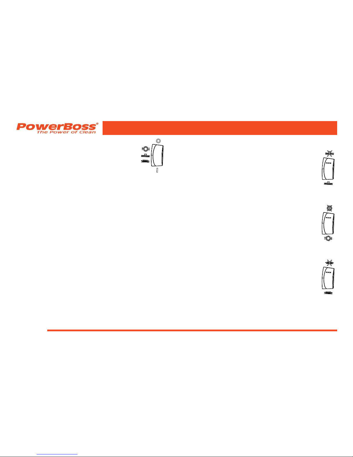
SQUEEGEE SWITCH
A separate Squeegee switch is provided. It can
be used to prevent the squeegee functions from
operating when the “One-Touch” switch is activated
(Allowing for scrubbing only or double scrubbing
operation). A red light on the switch will illumnate
when this switch is in the off (“X”) position.
SCRUB BRUSH SWITCH
A separate Scrub Brush switch is provided. It can
be used to prevent the main scrub brush functions
from operating when the “One-Touch” switch is
activated (Allowing for squeegee only operation).
A red light on the switch will illumnate when this
switch is in the off (“X”) position.
SIDE SCRUB BRUSH SWITCH - OPTION
A separate Side Scrub Brush Switch is provided
as an option. It can be used to prevent the side
brush from operating when the “One-Touch” switch
is activated. A red light on the switch will illumnate
when the scrub brush switch is in the on position
and this switch is in the off (“X”) position.
Nautilus Rider Scrubber/Sweeper #988749UM Rev. C 07/15
© 2014-2015 Minuteman International, Inc.
Page 27
MACHINE OPERATION
When the vehicle motion is stopped the brushes
(including the side brush, if installed) and solution ow will
automatically shut off. When the vehicle begins to move
the scrub brushes and the solution automatically resume
operation.
When the scrubber is driven in reverse the squeegee
automatically raises from the oor.
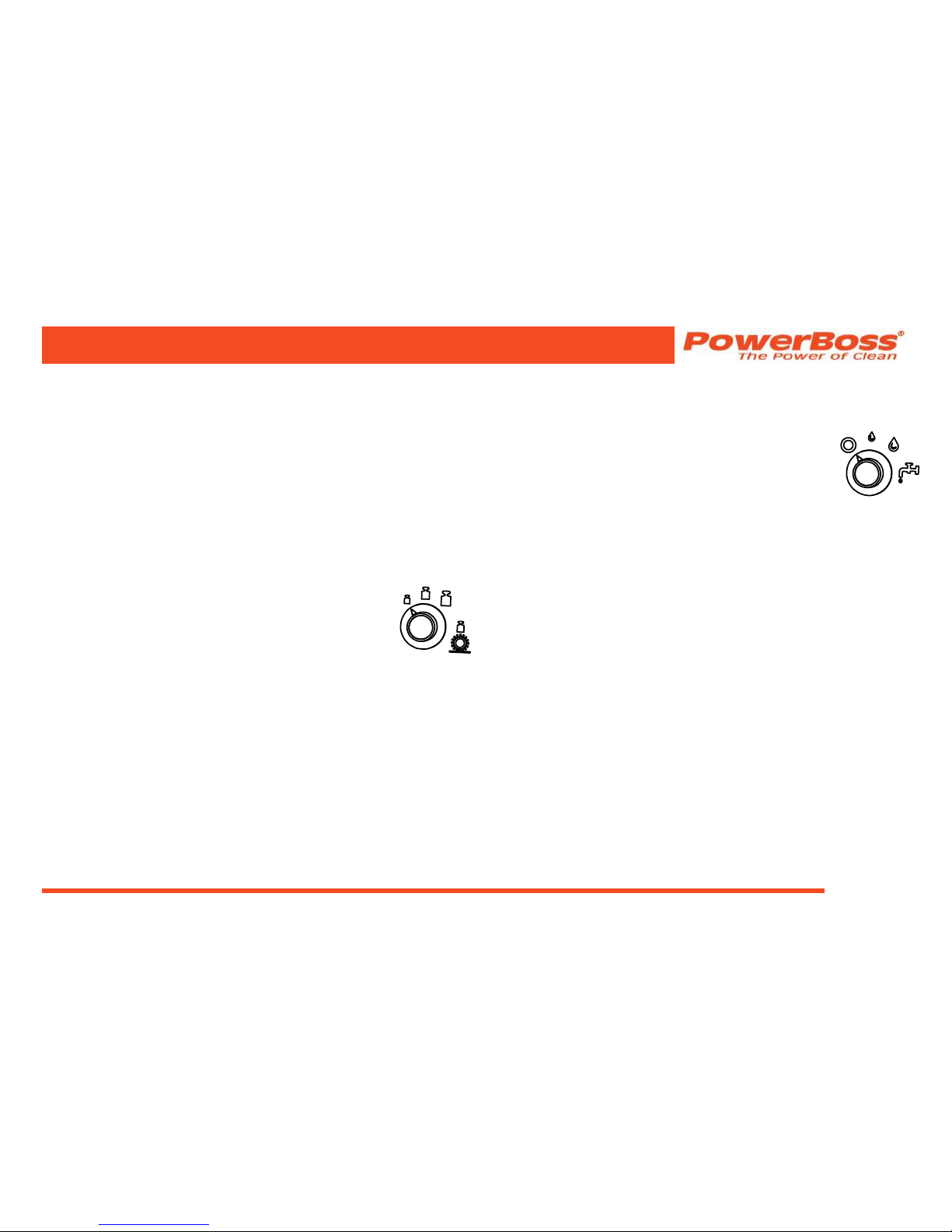
MAIN BRUSH SCRUB PRESSURE KNOB
The Main Brush Scrub Pressure is selected
using a rotary control knob which provides three
pressure settings: Light = 200 lb (90,7 kg);
Medium = 300 lb (136,1 kg); and Heavy = 400 lb
(181,4 kg). Upon start-up the system responds
to the last pressure setting used. The scrubbing
pressure can be changed while the scrubber is in
operation.
SIDE BRUSH SCRUB PRESSURE
The optional Side Brush Scrub Pressure is variable and
automatically changes to balance with the setting of the main
brush pressure.
SOLUTION CONTROL KNOB
The solution ow is selected using a three position
rotary knob which provides: Off, Low, and High
solution ow.
The Low ow setting is for normal scrubbing,
smooth oors, and light dirt. The ow rate is .88
gal/hr (3,33 L/hr), providing 2.0 hours of scrub time.
The High ow setting is for rough oors and heavy
or compacted dirt. The high ow rate is 1.50 gal/hr
(5,67 L/hr), providing 1.2 hours of scrub time.
Note: The solution ow starts and stops automatically when
the solution ow switch is set in the low or high position.
The ow can be manually shut off when sufcient solution is
already on the oor.
The side brush solution ow starts and stops automatically.
Ths side brush has only one ow rate. The ow rate is
factory set, but can be adjusted by turning the slotted screw
on the solution solenoid valve located below the frame just
behind the side scrub brush.

© 2014-2015 Minuteman International, Inc.
Nautilus Rider Scrubber/Sweeper #988749UM Rev. C 07/15
Page 28
CHOOSING THE CORRECT TYPE OF BRUSH
(FOR YOUR SCRUBBING APPLICATION)
The main and optional side scrub brushes are available in
the following types:
Polypropylene brush
This is a general-purpose brush good for most cleaning
applications.
Nylon brush
This is a soft brush good for light applications or when
scrubbing coated oors.
80 grit abrasive brush
This is a nylon brush impregnated with mild abrasive grit for
removing heavy stains and compacted dirt.
180 grit abrasive brush
This is a nylon brush impregnated with heavy abrasive grit
for removing heavy stains and compacted dirt. This brush is
good for heavy buildup grease or tire marks.
Note: Reference Nautilus Part Catalog for reordering main
and side scrub brushes.
MACHINE OPERATION
BASIC SCRUBBING/FILLING/
EMPTYING INFORMATION
Adjust the machine speed scrub brush pressure and solution
ow as required. Use the least amount of brush pressure
and solution necessary for the scrubbing application.
When the recovery tank is full the recovery tank indicator
light will illuminate and the scrubbing functions will shut off.
It is then necessary to drain and clean the recovery tank
and rell the solution tank before continuing the scrubbing
operation.
Nautilus Rider Scrubber/Sweeper #988749UM Rev. C 07/15
© 2014-2015 Minuteman International, Inc.
Page 29
MACHINE OPERATION
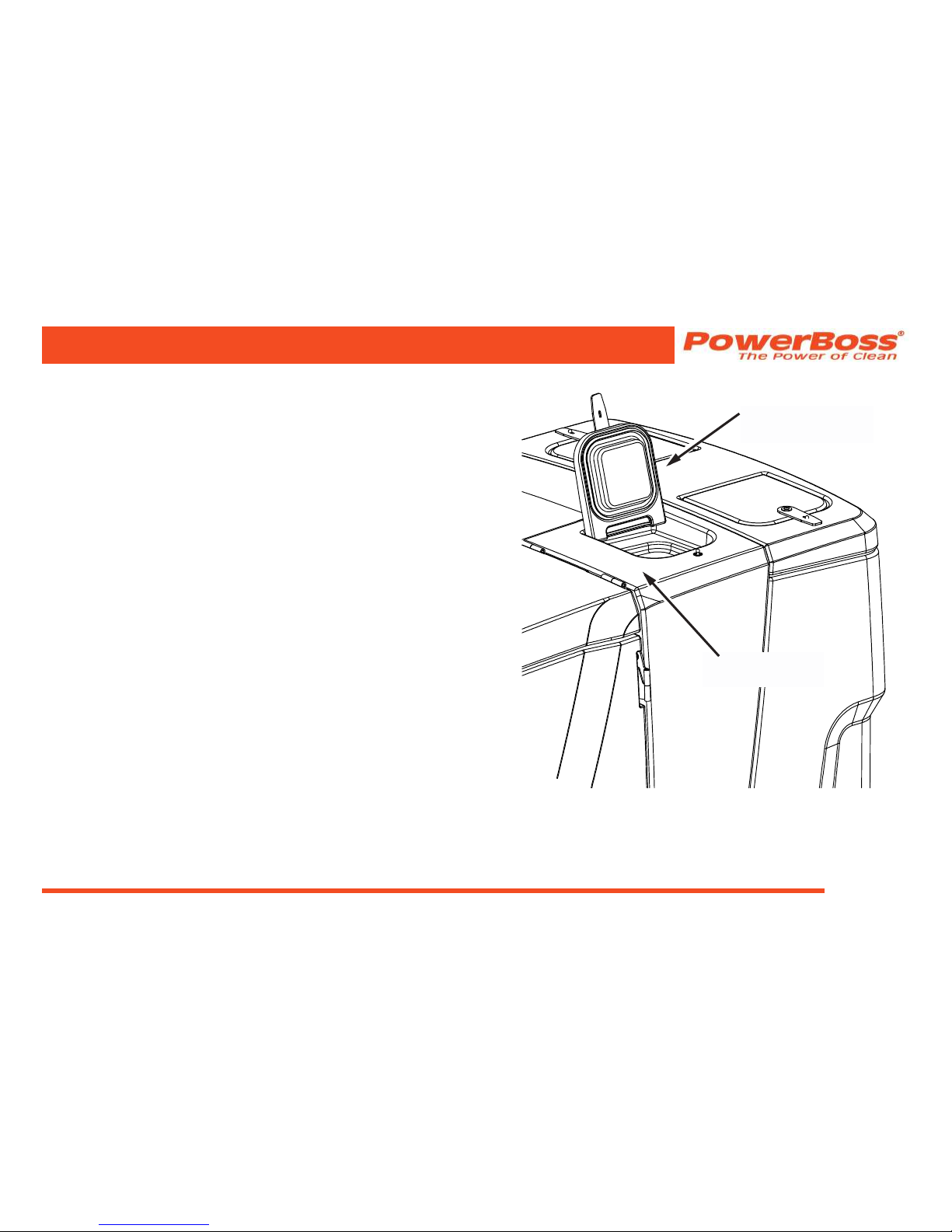
FILLING THE SOLUTION TANK
Open the top cover of the solution tank. Begin lling the
solution tank with clean water not to exceed 130°F (55.4°C).
When the tank is approximately half full add the appropriate
amount of detergent (Do not add detergent in solution tank
if you are using the optional chemical metering system
for applying detergent). Continue to ll the solution tank
with water. The tank is full when the water level reaches
the bottom of the metal level indicator (located inside the
solution tank).
If the machine is equipped with an optional chemical
metering system do not add detergent in the solution tank.
Instead, place a container of cleaning solution into the
chemical metering box and install the pump suction hose.
Note: Use only recommended cleaning detergents.
Machine damage due to improper detergent usage will void
the machine warranty.
SOLUTION
TANK
SOLUTION TANK
TOP COVER
Fig. 1
© 2014-2015 Minuteman International, Inc.
Nautilus Rider Scrubber/Sweeper #988749UM Rev. C 07/15
Page 30
MACHINE OPERATION
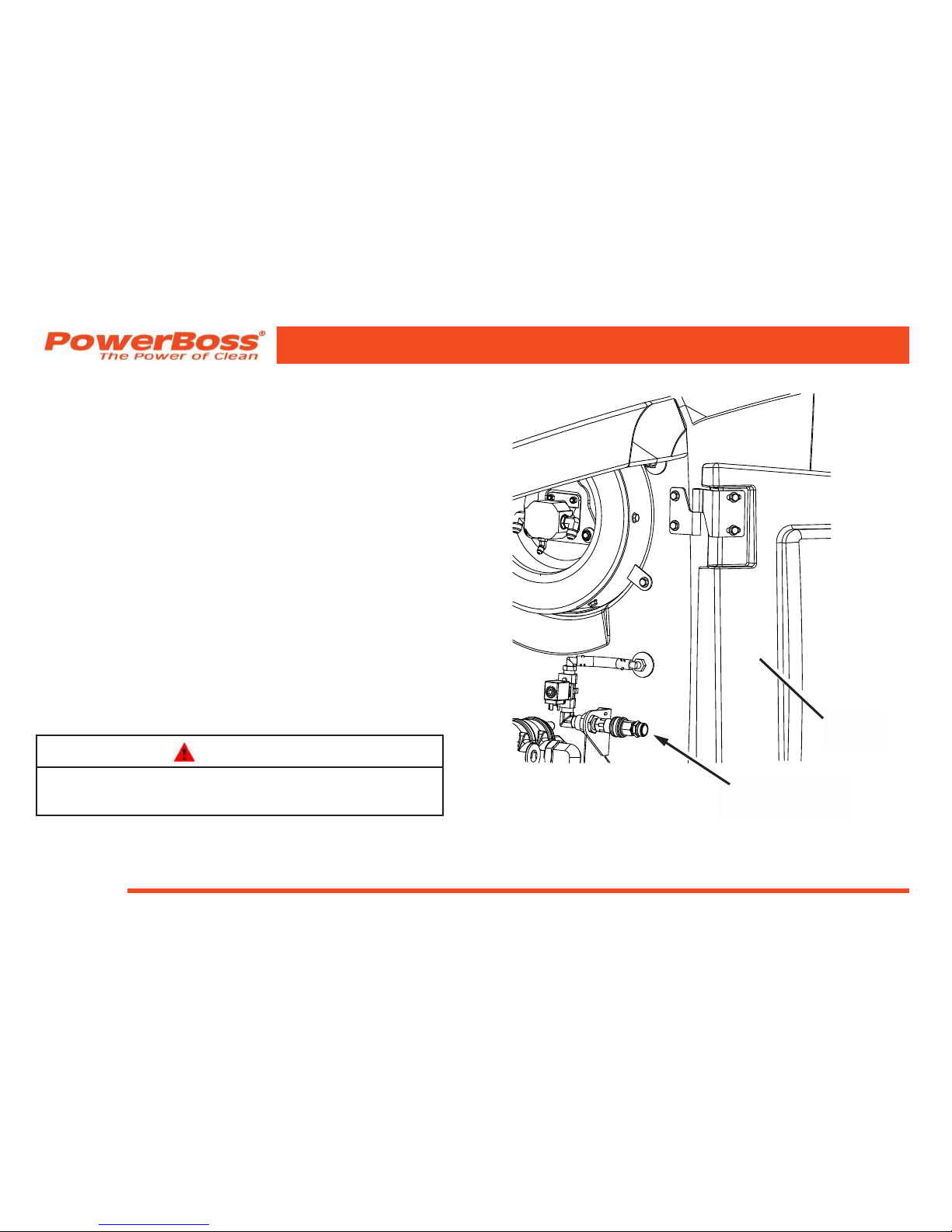
FILLING THE SOLUTION TANK
USING THE AUTO-FILL OPTION:
1. Park the machine on a level surface and set the parking
brake.
2. Turn the ignition key to the “on” position, do not start the
engine.
3. A. Open the side door.
B. Using the quick connector adapter on the end of a
water supply hose connect the supply hose to the
auto-ll connector located below the vacuum impeller.
C. Turn on the water supply. The water will automatically
shut off when the proper level is achieved.
D. When the solution tank is full, turn off the water supply.
E. Disconnect the garden hose and close the side door.
4. Turn the ignition key in the “off” position.
WARNING
Flammable materials can cause an explosion or re.
Do not use or ll ammable materials in the tank(s).
SIDE
DOOR
AUTO-FILL
CONNECTOR
Fig. 1
 Loading...