

Page 1
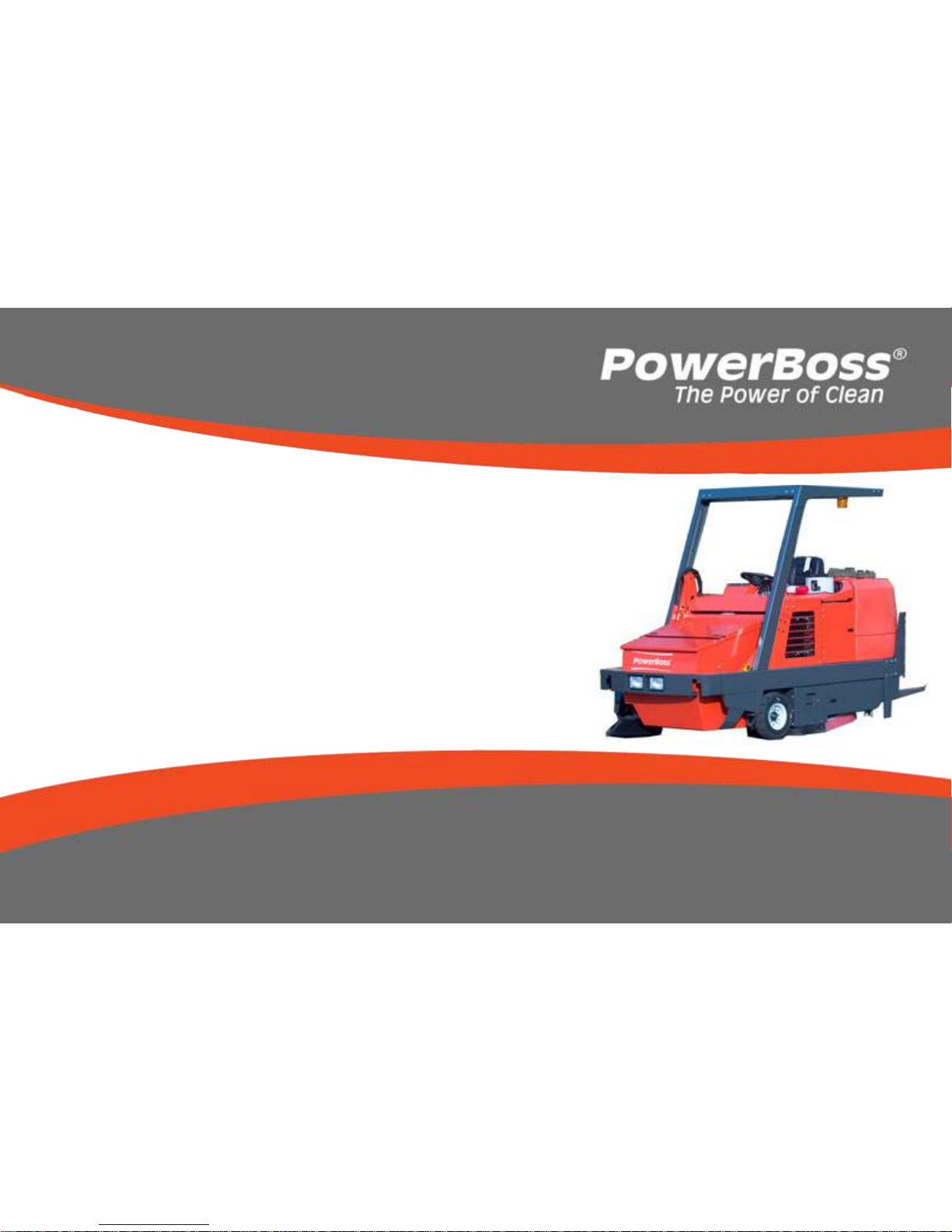
Commander T Series PB# 4100032 Rev.B 09/11
PowerBoss, Inc. Copyright 2011
Page 1
User Manual
Commander T Series
Models: T82, T82 Europe, T90,
Gasoline, LP & Diesel
PowerBoss, Inc.
A Member Of The Hako Group
PB# 4100032 Rev. C 03/12
Page 2

PowerBoss, Inc. Copyright 2011
Commander T Series PB# 4100032 Rev. C 03/12
Page 2
PREFACE
Thank you for your purchase of the now industry standard for sweepers. PowerBoss takes great pride in offering the most
dependable, reliable and best value in industrial power sweepers and sweeper / scrubbers. We set the standard.
Our Publishing Department would like to hear from you. If you see any errors, omissions or something that needs
clarication in this User Manual please let us know. We are working hard toward perfection in our corner of the process to
bring you the best you can buy. Please copy the form below, ll out and comment on how you found our catalog.
Thank you.
*Name______________________________________________________________________
*Title: ______________________________________________________________________
*Company Name: _____________________________________________________________
*Address: ____________________________________________________________________
*Country: ____________________________________________________________________
Type of equipment or model number: ______________________________________________
PREFACE
Page 3

Commander T Series PB# 4100032 Rev. C 03/12
PowerBoss, Inc. Copyright 2011
Page 3
Comments:
*Information is optional.
Please return to:
Manager, Publishing Department, International
PowerBoss, Inc.
175 Anderson Street
Aberdeen, North Carolina 28315 USA
Phone (800) 982-7141 Toll Free
(910) 944-2105 Local
E-Mail - [email protected]
PREFACE
Page 4

PowerBoss, Inc. Copyright 2011
Commander T Series PB# 4100032 Rev. C 03/12
Page 4
This is the User Manual for the PowerBoss Commander T Series Sweeper Scrubber.
This manual covers all Standard Commander T Series machine variations beginning May 2009.
We believe this machine will provide excellent service for many years.
However, the best results will be obtained if:
• The machine is operated with reasonable care.
• The machine is maintained regularly per the maintenance schedule provided in the User Manual.
• The machine is maintained with PowerBoss Inc. supplied or equivalent parts.
All right side and left side references to the machine (except for engine) are determined by facing the direction of forward
travel. The front of the engine or engine fan faces the rear of the machine. Some hardware considered to be common or
locally available has been omitted from the parts section to make this manual clear. Be sure to use equivalent hardware
when replacement becomes necessary.
The Model and Serial Number of your machine is shown on the I.D. name plate. This information is needed when
contacting Technical Support or when ordering parts. The I.D. plate is mounted on the console of the machine left of the
operator and adjacent the main broom adjustment access door.
Parts may be ordered by phone,fax or e-mail from any PowerBoss parts and service center. Before ordering parts or
supplies, be sure to have your machine model number and serial number handy. For your convenience Fill out the data
block below for future reference.
PREFACE
Page 5

Commander T Series PB# 4100032 Rev. C 03/12
PowerBoss, Inc. Copyright 2011
Page 5
Example I.D Plate;
MACHINE DATA
Fill out at installation
Serial Number: ___________________________________
Engine Serial Number: ____________________________
Sales Rep.: ______________________________________
Date of Install: ___________________________________
All information contained in this catalog is current at the time of printing However, PowerBoss reserves the right to make
changes at any time without notice.
©2011, PowerBoss, Inc., Printed in USA
PREFACE
Page 6

PowerBoss, Inc. Copyright 2011
Commander T Series PB# 4100032 Rev. C 03/12
Page 6
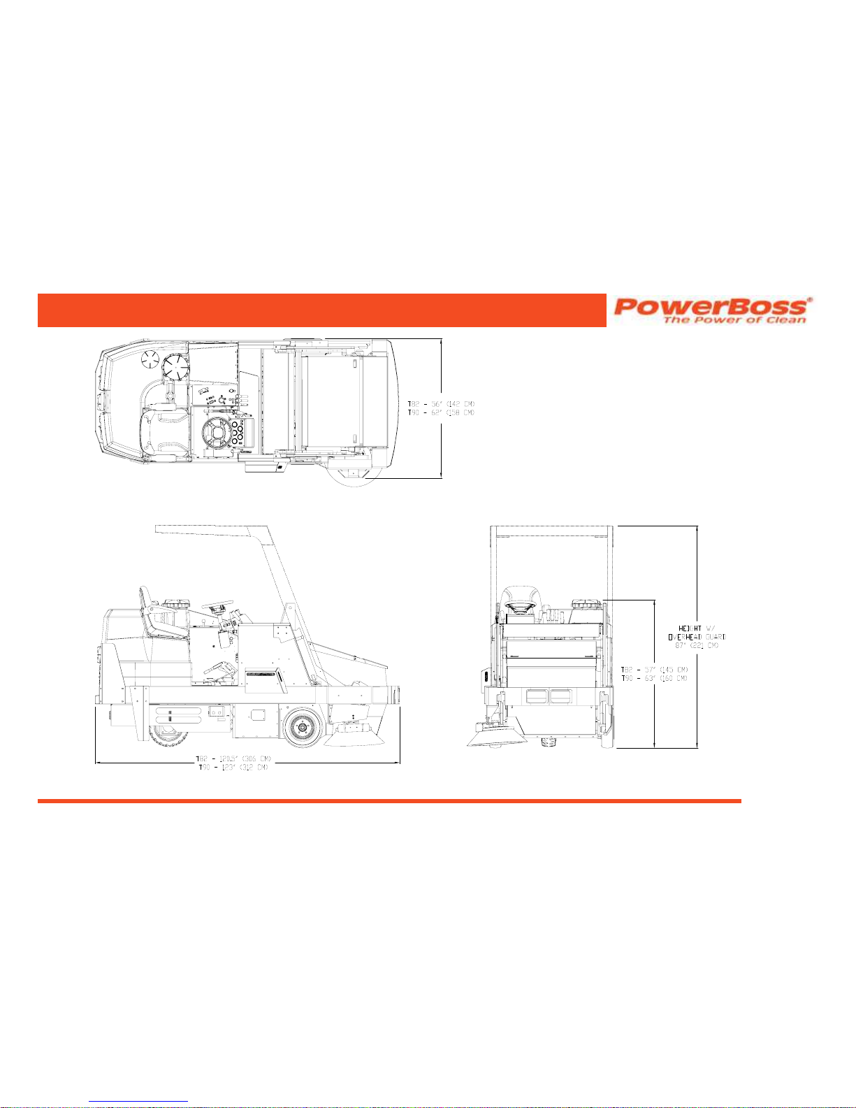
TECHNICAL SPECIFICATIONS
Model Commander T Series
Model No. TSS90DSL / TSS90DSLBR / TSS90LP / TSS90LPBR / 3333780 / 3333780BR / TSS82DSL /
TSS82LP / TSS82GAS / TSS82DSLCE / TSS82LPCE
DIMENSIONS & WEIGHT
T82 & T82 Europe T90
Length . . . . . . . . . . . . . . . . . . . 120.5 inches (306 cm) .123 inch (312 cm)
Width . . . . . . . . . . . . . . . . . . . . 56 inch (142 cm). . . . . .62 inch (158 cm)
Height . . . . . . . . . . . . . . . . . . . 57 inch (145 cm) . . . . . .63 inch (160 cm)
Height w/ overhead guard . . . 87 inch (221 cm). . . . . .87 inch (221 cm)
Height w/ cab. . . . . . . . . . . . . . 83.5 inch (212 cm) . . . .83.5 inch (212 cm)
Weight . . . . . . . . . . . . . . . . . . 2900 lbs (1315 kg).. . . .3400 lbs (1542 kg)
Minimum U-turn. . . . . . . . . . . . 120 inch (305 cm) . . . . .126 inch (320 cm)
SCRUBBING SYSTEM
Scrub path . . . . . . . . . . . . . . . . 42 inch (107 cm) . . . . . .48 inch (122 cm)
Scrub deck pressure . . . . . . . . 300 lbs (136 kg) . . . . . .300 lbs (136 kg)
Brush speed . . . . . . . . . . . . . . 250 rpm . . . . . . . . . . . . .250 rpm
Solution tank capacity . . . . . . . 68 gal (257 L) . . . . . . . .100 gal (378.5 L)
Recovery tank capacity . . . . . . 65 gal (246 L) . . . . . . . .100 gal (378.5 L)
Squeegee width. . . . . . . . . . . . 50 inch (127 cm). . . . . .50 inch (127 cm)
TECHNICAL SPECIFICATIONS
SWEEPING SYSTEM
T82 & T82 Europe T90
Sweep path . . . . . . . . . . . . . . . 54 inch (137 cm) . . . . . .60 inch (152 cm)
Main broom . . . . . . . . . . . . . . . 42 inch (107 cm) . . . . . .48 inch (122 cm)
Side broom . . . . . . . . . . . . . . . 24 inch (61 cm) . . . . . . .24 inch (61 cm)
Hopper type. . . . . . . . . . . . . . . high dump. . . . . . . . . . .high dump
Hopper volume . . . . . . . . . . . . 14 cu ft . . . . . . . . . . . . .16 cu ft
Hopper load capacity. . . . . . . . 1000 lbs (454 kg) . . . . .1200 lbs (544 kg)
Dust control . . . . . . . . . . . . . . . 100 sq ft . . . . . . . . . . . .100 sq ft
High dump . . . . . . . . . . . . . . . 60 inch (152 cm) . . . . . .60 inch (152 cm)
RTR (rotary trash relocation). . yes . . . . . . . . . . . . . . . .yes
OTHER SPECIFICATIONS
T82 & T82 Europe T90
Noise Level . . . . . . . . . . . . . . . 84.5 dBA . . . . . . . . . . . .84.5 dBA
Page 7
Commander T Series PB# 4100032 Rev. C 03/12
PowerBoss, Inc. Copyright 2011
Page 7
TECHNICAL SPECIFICATIONS
Page 8

PowerBoss, Inc. Copyright 2011
Commander T Series PB# 4100032 Rev. C 03/12
Page 8
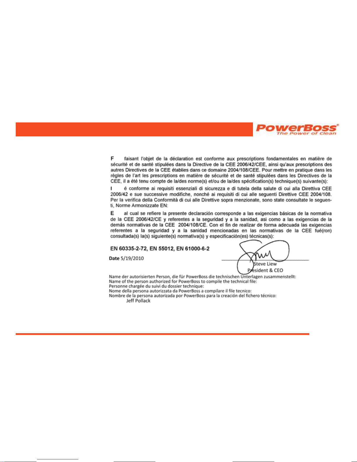
CE DECLARATION OF CONFORMITY
COMMANDER T82
DECLARATION OF CONFORMITY
Page 9
Commander T Series PB# 4100032 Rev. C 03/12
PowerBoss, Inc. Copyright 2011
Page 9
DECLARATION OF CONFORMITY
Page 10

PowerBoss, Inc. Copyright 2011
Commander T Series PB# 4100032 Rev. C 03/12
Page 10
TABLE OF CONTENTS
PREFACE . . . . . . . . . . . . . . . . . . . . . . . . . . . . . . 2
TECHNICAL SPECIFICATIONS. . . . . . . . . . . . . 6
DIMENSIONS & WEIGHT . . . . . . . . . . . . . . . . . . . . . . . . 6
SCRUBBING SYSTEM . . . . . . . . . . . . . . . . . . . . . . . . . . 6
CE DECLARATION OF CONFORMITY . . . . . . . 8
COMMANDER T82 . . . . . . . . . . . . . . . . . . . . . . . . . . . . . 8
FEATURES . . . . . . . . . . . . . . . . . . . . . . . . . . . . . 15
AIR-MOVING SYSTEM . . . . . . . . . . . . . . . . . . . . . . . . . . 15
ERGONOMICS SYSTEM
. . . . . . . . . . . . . . . . . . . . . . . . 15
DEBRIS-HANDLING SYSTEM
. . . . . . . . . . . . . . . . . . . . 15
DRIVE-TRAIN SYSTEM
. . . . . . . . . . . . . . . . . . . . . . . . . 15
CHASSIS SYSTEM . . . . . . . . . . . . . . . . . . . . . . . . . . . . . 15
ENVIRONMENTAL FRIENDLY FEATURES. . . . . . . . . . 16
WATER CONSERVATION
. . . . . . . . . . . . . . . . . . . . 16
CLEAN AIR
. . . . . . . . . . . . . . . . . . . . . . . . . . . . . . . . 16
LOWER EMISSIONS. . . . . . . . . . . . . . . . . . . . . . . . . 16
SAFER WORK ENVIRONMENT
. . . . . . . . . . . . . . . . 16
CLEAN ENERGY
. . . . . . . . . . . . . . . . . . . . . . . . . . . . 16
CLEAN ENERGY
. . . . . . . . . . . . . . . . . . . . . . . . . . . . 16
SAFETY INFORMATION . . . . . . . . . . . . . . . . . . 17
IMPORTANT SAFETY INSTRUCTIONS. . . . . . . . . . . . . 17
FOR SAFETY DURING OPERATION. . . . . . . . . . . . . . . 17
FOR SAFETY WHEN SERVICING OR MAINTAINING
MACHINE
. . . . . . . . . . . . . . . . . . . . . . . . . . . . . . . . . . . . 18
SAFETY SYMBOLS
. . . . . . . . . . . . . . . . . . . . . . . . . . . . 18
SAFETY DECALS. . . . . . . . . . . . . . . . . . . . . . . . . . . . . . 19
BASIC POWERBOSS® SAFETY. . . . . . . . . . . . 22
MACHINE OPERATION
. . . . . . . . . . . . . . . . . . . 25
BASIC OPERATING CONTROLS AND INDICATORS 25
IGNITION SWITCH
. . . . . . . . . . . . . . . . . . . . . . . . . . 25
HORN
. . . . . . . . . . . . . . . . . . . . . . . . . . . . . . . . . . . . 25
LIGHT SWITCH . . . . . . . . . . . . . . . . . . . . . . . . . . . . . 25
HOUR METER. . . . . . . . . . . . . . . . . . . . . . . . . . . . . . 25
ENGINE COOLANT TEMPERATURE GAUGE . . . . . 25
ENGINE OIL PRESSURE
. . . . . . . . . . . . . . . . . . . . . 25
VOLTMETER AMP GAUGE
. . . . . . . . . . . . . . . . . . . . 25
FUEL LEVEL GAUGE
. . . . . . . . . . . . . . . . . . . . . . . . 25
THROTTLE (DIESEL)
. . . . . . . . . . . . . . . . . . . . . . . . 26
GLOW PLUG BUTTON (DIESEL ONLY). . . . . . . . . . 26
TABLE OF CONTENTS
Page 11

Commander T Series PB# 4100032 Rev. C 03/12
PowerBoss, Inc. Copyright 2011
Page 11
MURPHY SWITCH (DIESEL ONLY) . . . . . . . . . . . . . 26
SEAT ADJUSTMENT. . . . . . . . . . . . . . . . . . . . . . . . . 26
PARKING BRAKE
. . . . . . . . . . . . . . . . . . . . . . . . . . . 26
BRAKE
. . . . . . . . . . . . . . . . . . . . . . . . . . . . . . . . . . . . 26
THROTTLE (GAS AND LP)
. . . . . . . . . . . . . . . . . . . . 28
CHECK ENGINE INDICATOR (GAS AND LP ONLY)
28
SWEEPING / SCRUBBING CONTROLS AND
INDICATORS. . . . . . . . . . . . . . . . . . . . . . . . . . . . . . . . . . 30
BROOM CONTROL LEVER . . . . . . . . . . . . . . . . . . . 30
MAIN BROOM HANDLE
. . . . . . . . . . . . . . . . . . . . . . 30
SIDE BROOM HANDLE
. . . . . . . . . . . . . . . . . . . . . . 30
SCRUB HEAD SWITCH
. . . . . . . . . . . . . . . . . . . . . . 32
SCRUB DECK GAUGE . . . . . . . . . . . . . . . . . . . . . . . 32
IMPELLER LEVER
. . . . . . . . . . . . . . . . . . . . . . . . . . 32
IMPELLER STOP CONTROL
. . . . . . . . . . . . . . . . . . 32
SQUEEGEE SWITCH
. . . . . . . . . . . . . . . . . . . . . . . . 32
SOLUTION LEVER
. . . . . . . . . . . . . . . . . . . . . . . . . . 32
SOLUTION TANK EMPTY INDICATOR. . . . . . . . . . . 32
RECOVERY TANK FULL INDICATOR
. . . . . . . . . . . . 32
DEBRIS HOPPER DUMP CONTROLS
. . . . . . . . . . . . . 34
HIGH DUMP
. . . . . . . . . . . . . . . . . . . . . . . . . . . . . . . 34
Lever 1 . . . . . . . . . . . . . . . . . . . . . . . . . . . . . . . . . 34
Lever 2 . . . . . . . . . . . . . . . . . . . . . . . . . . . . . . . . . 34
HOPPER UNLOCK BUTTON
. . . . . . . . . . . . . . . . . . 34
ROTARY TRASH RELOCATOR (RTR™)
. . . . . . . . . 34
HOPPER FILTER SHAKER BUTTON
. . . . . . . . . . . . 34
FIRE IN THE HOPPER INDICATOR (OPTIONAL)
34
CLOGGED FILTER INDICATOR (OPTIONAL)
. . . . . 35
OPERATING PROCEDURES . . . . . . . . . . . . . . . . . . . . . 36
PRE-OPERATION CHECKS . . . . . . . . . . . . . . . . . . . 36
STARTING . . . . . . . . . . . . . . . . . . . . . . . . . . . . . . . . . 36
Gasoline or LP Power Units . . . . . . . . . . . . . . . . . 36
Diesel Power Units
. . . . . . . . . . . . . . . . . . . . . . . . 37
TRAVELING FORWARD OR BACKWARDS. . . . . . . 37
Forward
. . . . . . . . . . . . . . . . . . . . . . . . . . . . . . . . 37
Reverse
. . . . . . . . . . . . . . . . . . . . . . . . . . . . . . . . 37
SLOWING AND STOPPING
. . . . . . . . . . . . . . . . . . . 37
SWEEPING
. . . . . . . . . . . . . . . . . . . . . . . . . . . . . . . . 38
EMPTYING THE HOPPER WITH HIGH DUMP
FEATURE
. . . . . . . . . . . . . . . . . . . . . . . . . . . . . . . . . 38
TABLE OF CONTENTS
Page 12

PowerBoss, Inc. Copyright 2011
Commander T Series PB# 4100032 Rev. C 03/12
Page 12
USING THE ROTARY TRASH RELOCATOR
(RTR™) . . . . . . . . . . . . . . . . . . . . . . . . . . . . . . . . . . . 40
TO SHAKE THE FILTER
. . . . . . . . . . . . . . . . . . . . . . 41
FIRE IN THE HOPPER
. . . . . . . . . . . . . . . . . . . . . . . 41
SCRUBBING
. . . . . . . . . . . . . . . . . . . . . . . . . . . . . . . 42
Operating the Scrub Brushes
. . . . . . . . . . . . . . . . 42
Starting Solution Flow . . . . . . . . . . . . . . . . . . 42
Lower The Squeegee . . . . . . . . . . . . . . . . . . . 42
FILLING THE SOLUTION TANK
. . . . . . . . . . . . . . . . 43
DRAINING THE RECOVERY TANK
. . . . . . . . . . . . . 44
CLEANING THE RECOVERY TANK . . . . . . . . . . . . . 44
SQUEEGEE WAND (OPTION)
. . . . . . . . . . . . . . . . . 45
BLOWER (OPTION)
. . . . . . . . . . . . . . . . . . . . . . . . . 46
TRANSPORTING THE MACHINE. . . . . . . . . . . . . . . 46
Using a Trailer or Transport Vehicle. . . . . . . . . . . 46
Pushing the Machine
. . . . . . . . . . . . . . . . . . . . . . 46
PREVENTATIVE MAINTENANCE . . . . . . . . . . . 47
INTRODUCTION . . . . . . . . . . . . . . . . . . . . . . . . . . . . . . . 47
SCHEDULED MAINTENANCE CHART . . . . . . . . . . . . . 48
PREVENTATIVE MAINTENANCE INSTRUCTIONS
52
ENGINE . . . . . . . . . . . . . . . . . . . . . . . . . . . . . . . . . . . 52
Air Intake System . . . . . . . . . . . . . . . . . . . . . . . . . 52
Check Air Filter Service Indicator . . . . . . . . . . 52
Air Filter Element Removal. . . . . . . . . . . . . . . 53
Air Filter Cleaning. . . . . . . . . . . . . . . . . . . . . . 54
Air Filter Inspection. . . . . . . . . . . . . . . . . . . . . 54
Air Filter Installation
. . . . . . . . . . . . . . . . . . . . 54
ELECTRICAL SYSTEM
. . . . . . . . . . . . . . . . . . . . . . 55
Battery Cleaning. . . . . . . . . . . . . . . . . . . . . . . . . . 55
Battery Replacement
. . . . . . . . . . . . . . . . . . . . . . 55
Circuit Breaker . . . . . . . . . . . . . . . . . . . . . . . . . . . 56
Fuses . . . . . . . . . . . . . . . . . . . . . . . . . . . . . . . . . . 56
FUEL SYSTEM . . . . . . . . . . . . . . . . . . . . . . . . . . . . . 57
TABLE OF CONTENTS
Page 13

Commander T Series PB# 4100032 Rev. C 03/12
PowerBoss, Inc. Copyright 2011
Page 13
COOLANT SYSTEM. . . . . . . . . . . . . . . . . . . . . . . . . 58
Blowing Out Radiator Fins . . . . . . . . . . . . . . . . . . 58
Reverse Flow Flushing. . . . . . . . . . . . . . . . . . . . . 58
LUBRICATION. . . . . . . . . . . . . . . . . . . . . . . . . . . . . . 59
Changing Engine Oil
. . . . . . . . . . . . . . . . . . . . . . 59
LUBRICATION POINTS
. . . . . . . . . . . . . . . . . . . . . . 59
Steering Fork Assembly and Steering Link
Ball Joints. . . . . . . . . . . . . . . . . . . . . . . . . . . . . . . 59
Steering Cylinder
. . . . . . . . . . . . . . . . . . . . . . . . . 60
Latches & Hinges . . . . . . . . . . . . . . . . . . . . . . . . . 60
Hopper Lift Arm Mounts
. . . . . . . . . . . . . . . . . . . . 60
HYDRAULICS SYSTEM . . . . . . . . . . . . . . . . . . . . . . 62
Filling The Fluid Reservoir
. . . . . . . . . . . . . . . . . . 62
Hydraulic Fluid Viscosity Specications . . . . . 62
Maintaining Hydraulic Oil Cooler Efciency . . . . . 62
Changing The Hydraulic Fluid
. . . . . . . . . . . . . . . 62
Changing The Hydraulic Fluid Filter. . . . . . . . . . . 63
SWEEP COMPONENTS . . . . . . . . . . . . . . . . . . . . . . 64
Broom Door Flap Inspection
. . . . . . . . . . . . . . . . 64
Broom Door Flap Replacement and Adjustment
64
Main Broom Pattern Check
. . . . . . . . . . . . . . . . . 65
Main Broom Height Adjustment
. . . . . . . . . . . . . . 66
Main Broom Taper Adjustment . . . . . . . . . . . . . . . 67
Main Broom Replacement
. . . . . . . . . . . . . . . . . . 68
Side Broom Angle Adjustment
. . . . . . . . . . . . . . . 69
Side Broom Height (Wear) Adjustment
. . . . . . . . 70
Side Broom Lift Cable Adjustment
. . . . . . . . . 71
Side Broom Replacement . . . . . . . . . . . . . . . . . . 71
SCRUB & WATER PICK-UP COMPONENTS . . . . . . 72
Scrub Brush Replacement . . . . . . . . . . . . . . . . . . 72
Scrubhead Gauge Adjustment . . . . . . . . . . . . . . . 72
Scrubhead Adjustment. . . . . . . . . . . . . . . . . . . . . 73
TABLE OF CONTENTS
Page 14

PowerBoss, Inc. Copyright 2011
Commander T Series PB# 4100032 Rev. C 03/12
Page 14
MAIN SQUEEGEE COMPONENTS . . . . . . . . . . . . . 75
CHECKING and Adjusting the Rear Main
Squeegee Flare
. . . . . . . . . . . . . . . . . . . . . . . . . . 75
Turning or Replacing the Rear Squeegee Blade
76
Main Squeegee Tool Removal . . . . . . . . . . . . . . . 77
Main Squeegee Tool Installation
. . . . . . . . . . . . . 77
Inner Squeegee Replacement . . . . . . . . . . . . . . . 77
Auto Squeegee Lift Mechanism . . . . . . . . . . . . . . 77
HOPPER
. . . . . . . . . . . . . . . . . . . . . . . . . . . . . . . . . . 78
Hopper Filter Removal . . . . . . . . . . . . . . . . . . . . . 78
Hopper Filter Cleaning . . . . . . . . . . . . . . . . . . . . . 79
Hopper Filter Replacement
. . . . . . . . . . . . . . . . . 79
Flap Replacement
. . . . . . . . . . . . . . . . . . . . . . . . 80
Frame Seal Replacement
. . . . . . . . . . . . . . . . . . 80
Front Frame Seal
. . . . . . . . . . . . . . . . . . . . . . 80
Side Frame Seal. . . . . . . . . . . . . . . . . . . . . . . 80
Floor Clearance
. . . . . . . . . . . . . . . . . . . . . . . . . . 81
Vacuum Gasket Mount Adjustment
. . . . . . . . . . . 82
PARKING BRAKE . . . . . . . . . . . . . . . . . . . . . . . . . . . 82
Adjusting The Parking Brake Cable Length . . . . . 83
Cable Adjustment for Standard brake
. . . . . . . . . 83
CHANGING SOLID TIRES
. . . . . . . . . . . . . . . . . . . . 84
Front Tire
. . . . . . . . . . . . . . . . . . . . . . . . . . . . . . . 84
Rear Tire
. . . . . . . . . . . . . . . . . . . . . . . . . . . . . . . 84
MISCELLANEOUS ADJUSTMENTS. . . . . . . . . . . . . 84
Anti-Static Chain Adjustment
. . . . . . . . . . . . . . . . 84
Latch and Hinge Maintenance . . . . . . . . . . . . . . . 84
Cables
. . . . . . . . . . . . . . . . . . . . . . . . . . . . . . . . . 84
TROUBLESHOOTING . . . . . . . . . . . . . . . . . . . . 85
TROUBLESHOOTING CHART . . . . . . . . . . . . . . . . . . . . 85
TABLE OF CONTENTS
Page 15

Commander T Series PB# 4100032 Rev. C 03/12
PowerBoss, Inc. Copyright 2011
Page 15
FEATURES
AIR-MOVING SYSTEM
• Dual-phase dust ltration
• Built-in pre-ltering & ultra-ne screen panel lters for
dust control
• Aggressive electric lter shakers
• Shock-mounted hydraulic impeller
• Engine area shielded from exhaust air
• Dust Control Filter: 100 Sq. Ft. total
• Timed Electric Filter Shakers
• Clogged Filter Indicator
• Fire-in-hopper Indicator
ERGONOMICS SYSTEM
• Roomy, open cockpit with extra comfort
• Adjustable, high-back seat with arm rests
• Power steering
• Comfortable pedal/controls placement
• Full instrumentation for all functions
DEBRIS-HANDLING SYSTEM
• Direct throw sweeping method
• Oversized hopper with RTR®
• Quick-change, oating 48” main broom & retractable
side brooms
• Dual-performance sweep mode
• Multi-Level Hopper Dumping
DRIVE-TRAIN SYSTEM
• Industrial liquid-cooled engine
• Heavy-duty radiator & Tri-phase air cleaner
• Hydraulics protection package
• 4-Core Radiator
• Industrial smooth ride tires for traction and reliability
CHASSIS SYSTEM
• Massive One-Piece, unitized steel frame
FEATURES
Page 16

PowerBoss, Inc. Copyright 2011
Commander T Series PB# 4100032 Rev. C 03/12
Page 16
FEATURES
ENVIRONMENTAL FRIENDLY FEATURES
WATER CONSERVATION
Aqua-Stop saves water usage by 50%, water is released
through a pump system providing greater control of water
usage than gravity systems
CLEAN AIR
High-performance lter system dramatically reduces the
release of dust and debris back into the air, dust vacuum
ensures that dust is put directly into the hopper, bristle
pattern on main broom increases dust control.
LOWER EMISSIONS
All gas and LP engines meet Tier 2 specications, catalyst
mufers, battery operated available, diesel operated
available, bio-diesel fuel can be used in Kubota engine
SAFER WORK ENVIRONMENT
Orange machines are highly visible to others in the
workplace, simple controls reduce operator error, onebutton scrub, horn, re in hopper indicator, effective braking
system, “belly bar” prevents operator from being pinned
behind machine when in reverse, parabolic squeegee picks
up all water leaving the scrub path virtually dry for trafc,
seat equipped with safety shut-off switch, also available:
overhead guard, back-up alarm, warning beacon
CLEAN ENERGY
Bio-diesel fuel can be used in Kubota engines
CLEAN ENERGY
Aqua-Stop saves chemical usage by 50%, pump system
for water and chemical release allows for better control of
chemical usage, chemical metering system is available
as an option and regulates chemical usage to the correct
dose.
Page 17

Commander T Series PB# 4100032 Rev. C 03/12
PowerBoss, Inc. Copyright 2011
Page 17
SAFETY INFORMATION
IMPORTANT SAFETY INSTRUCTIONS
Operators must read and understand this manual before
operating or maintaining this machine.
Do not operate this machine in ammable or explosive
areas.
This machine is designed solely for removing dirt,
dust and debris in an outdoor or indoor environment.
PowerBoss does not recommend using this machine in
any other capacity.
The following information below may cause a potential
hazard to the operator and equipment. Read this manual
carefully and be aware when these conditions can
exist. Take necessary steps to locate all safety devices
on the machine and train the personnel operating the
machine. Report any machine damage or faulty operation
immediately. Do not use machine if it is not in proper
operating condition.
FOR SAFETY DURING OPERATION
Keep hands and feet clear of moving parts while machine is in
operation.
Make sure all safety devices are in place and operate properly.
All covers, doors and latches must be closed and fastened before
use.
During operation, attention should be paid to other persons in the
work area and especially if small children are present.
Components can cause an explosion when operated near
explosive materials or vapor. Do not operate this machine near
ammable materials such as solvents, thinners, fuels, grain dust,
etc.
Store or park this machine on a level surface only. To prevent
unauthorized use, machine should be stored or parked with the
key removed.
This machine is designed for level operation only. Do not operate
on ramps or inclines greater than 2%.
This machine is not suitable for picking up hazardous dusts.
Use caution when moving this machine into areas that are below
freezing temperatures.
SAFETY INFORMATION
Page 18
PowerBoss, Inc. Copyright 2011
Commander T Series PB# 4100032 Rev. C 03/12
Page 18
FOR SAFETY WHEN SERVICING OR
MAINTAINING MACHINE
Stop on level surface.
Disconnect the power to the machine when servicing.
Avoid moving parts. Do not wear loose jackets, shirts, or
sleeves when working on machine.
Avoid contact with battery acid. Battery acid can cause
burns. When working on or around batteries, wear
protective clothing and safety glasses. Remove metal
jewelry. Do not lay tools or metal objects on top of battery.
Authorized personnel must perform repairs and
maintenance. Use PowerBoss supplied replacement parts.
SAFETY SYMBOLS
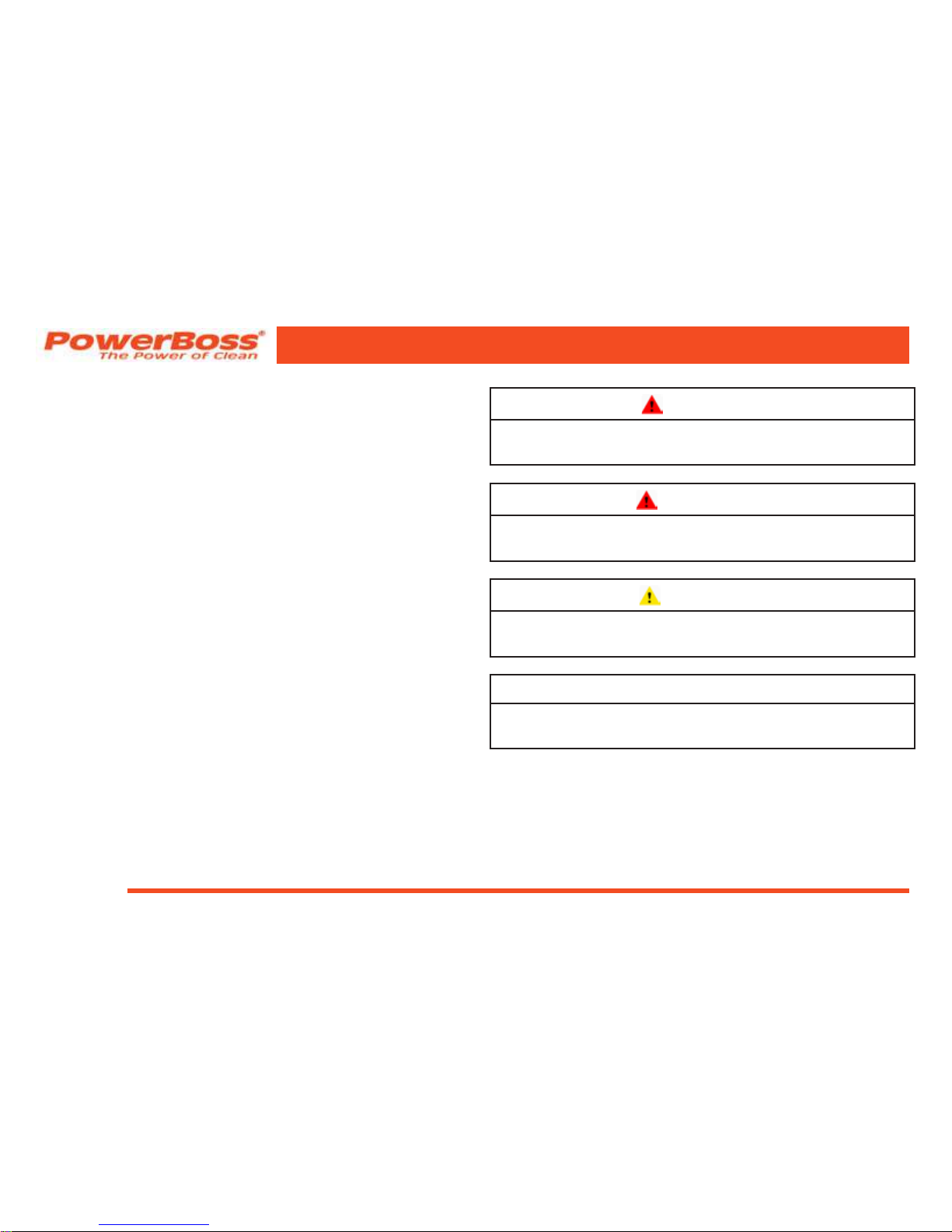
Five symbols are used throughout this manual to
emphasize various levels of safety information. These
symbols and the meaning of each are listed below.
DANGER
To warn of immediate hazards which will result in
severe personal injury or death
WARNING
To warn of hazards or unsafe practices which
could result in severe personal injury or death.
CAUTION
To warn of hazards or unsafe practices which
could result in minor personal injury.
ATTENTION!
To warn of practices which could result in
extensive equipment damage.
NOTE: To direct your attention to important
equipment information or special
instructions for preventing damage to
equipment
SAFETY INFORMATION
Page 19

Commander T Series PB# 4100032 Rev. C 03/12
PowerBoss, Inc. Copyright 2011
Page 19
Symbols at the top of the list are the strongest warnings.
However, all symbols represent important information
which should be observed to protect you and others from
harm and injury, and to prevent damage to the equipment.
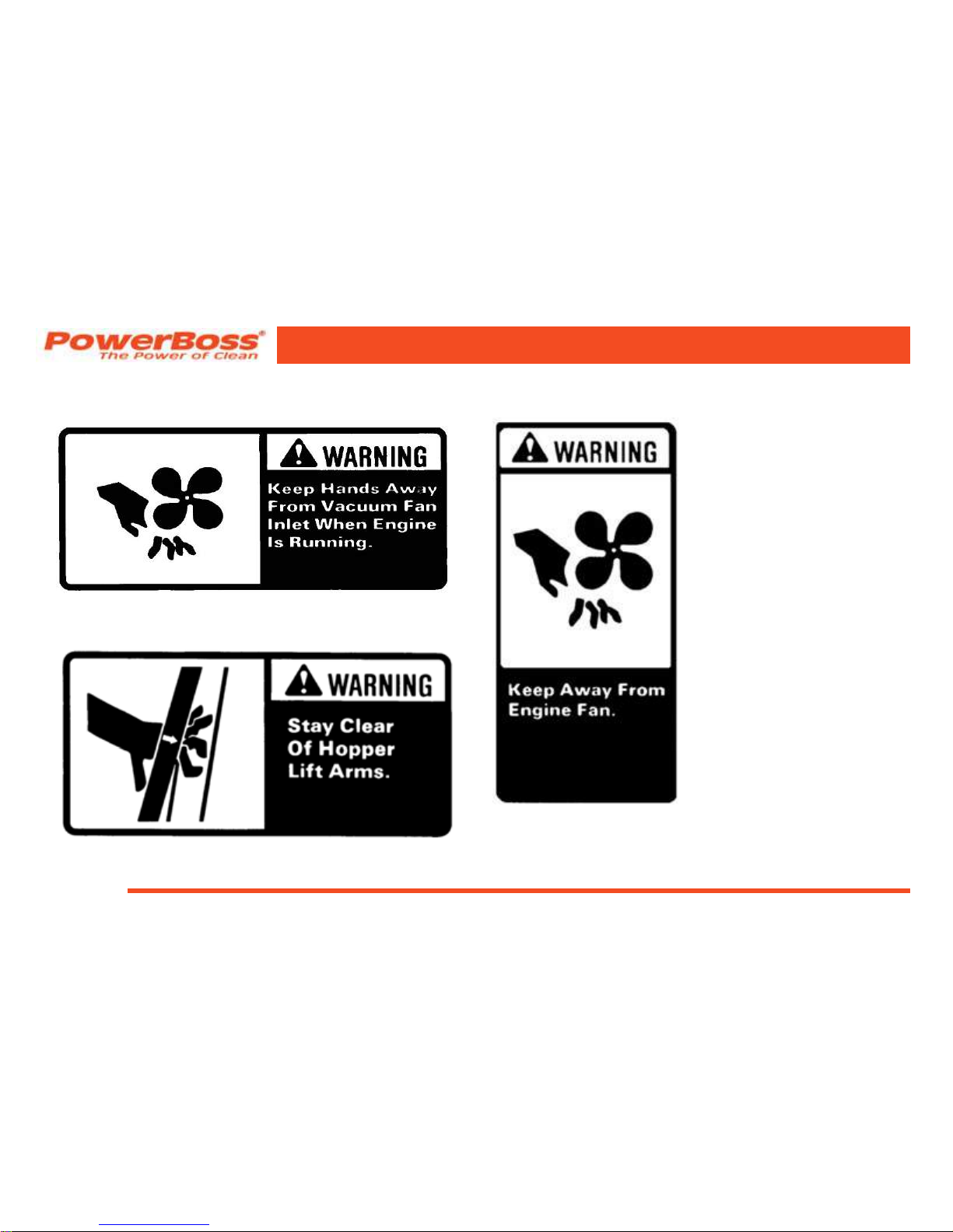
SAFETY DECALS
Decals directly attached to various parts of the unit are
highly visible safety reminders which should be read
and observed. Make sure the decals are replaced if they
become illegible or damaged.
Located in the drive compartment:
Part Number 301854
SAFETY INFORMATION
Page 20
PowerBoss, Inc. Copyright 2011
Commander T Series PB# 4100032 Rev. C 03/12
Page 20
Located at the Impeller:
Part Number 301729
Located on the Secondary Lift Arm:
Part Number 301732
Located on the shroud of the radiator:
Part Number 301733
SAFETY INFORMATION
Page 21

Commander T Series PB# 4100032 Rev. C 03/12
PowerBoss, Inc. Copyright 2011
Page 21
Located on the shroud of the radiator:
Part Number 301728
Located on the Lift Arm:
Part Number 301731
Located on the shroud of the radiator:
Part Number 301730
SAFETY INFORMATION
Page 22

PowerBoss, Inc. Copyright 2011
Commander T Series PB# 4100032 Rev. C 03/12
Page 22
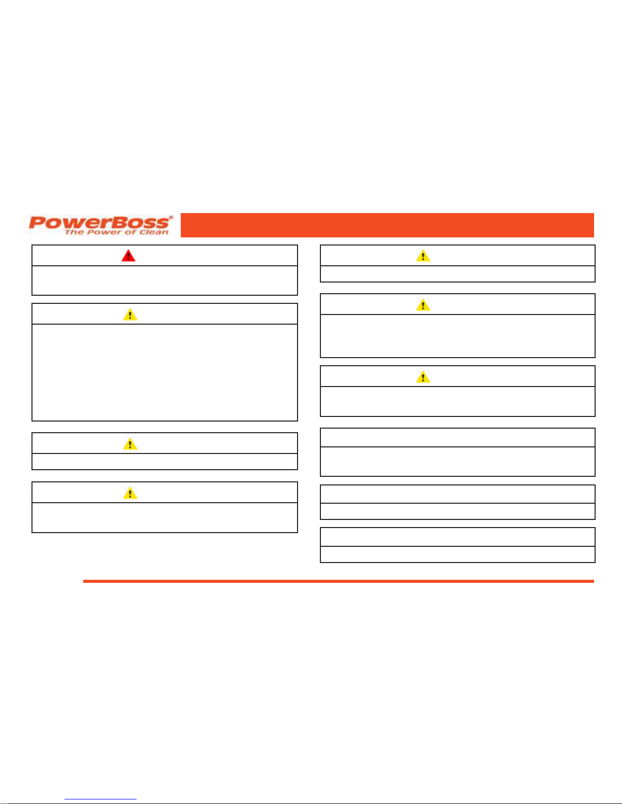
BASIC POWERBOSS® SAFETY
PowerBoss® sweeper scrubbers should never be operated
unless:
1. The operator is trained and authorized to operate
the equipment and,
2. The equipment is free of malfunctions.
Malfunctioning equipment should be removed from
service.
DANGER
Keep cigarettes, matches and all other ame
sources away from the sweeper. Gasoline, LP
gas and diesel fuel are highly ammable. Lead
acid batteries are equally dangerous due to the
highly explosive hydrogen gas they emit.
WARNING
Do not operate an LP powered sweeper
when any component in the fuel system is
malfunctioning or leaking.
WARNING
Before starting the engine, make sure that:
* You have read and understand the User Manual
* You are securely seated in the operator’s seat.
* The parking brake is locked.
* The directional control pedal is in neutral.
* The throttle is in idle.
* Hydraulic controls are in the OFF position.
WARNING
During operation:
* Keep your hands and body clear of moving
parts, especially when the hopper or lift arms
are partially or fully raised.
* Make sure others in the area stay clear of the
equipment and moving parts.
* Never attempt to dump debris from a dock or
mezzanine. Dump from ground level only.
SAFETY INFORMATION
Page 23

Commander T Series PB# 4100032 Rev. C 03/12
PowerBoss, Inc. Copyright 2011
Page 23
WARNING
When leaving the sweeper unattended:
* Place the controls in the OFF position.
* Set the parking brake.
* Shut off the engine.
WARNING
When servicing or repairing the fuel system:
* Work in a properly ventilated area, do not
smoke or allow an open ame near the fuel
system.
* Never bypass safety components unless you
are testing them.
* Never bypass the fuel lter lock, except when
testing them (and always reconnect them
after testing).
* Wear gloves to disconnect the tank coupling.
WARNING
During cleaning and maintenance:
* Always stop the engine and set the parking
brake before servicing.
* Never use detergents or cleansers that are
ammable or combustible.
* Never inate a pneumatic tire without using a
safety cage.
* Do not attempt any impeller adjustment unless
you have shut off the engine. Never place your
hands near the intake hoses or inlet when the
engine is running.
* Always engage the safety arm before servicing
the hopper. Do not rely on the hydraulic
cylinder to keep the hopper raised.
* Never test for hydraulic hose leaks using your
hand or any other part of your body. High
pressure leaks can be very dangerous and
should only be checked using a piece or paper.
SAFETY INFORMATION
Page 24
PowerBoss, Inc. Copyright 2011
Commander T Series PB# 4100032 Rev. C 03/12
Page 24
WARNING
Replace any defective safety components
before operating the sweeper.
CAUTION
Do not drive with the hopper in the raised
position except the few feet necessary to
position the hopper over the dumpster or
receptacle. Driving with the hopper raised
reduces visibility and creates conditions
for striking over-head objects, throwing the
machine off-balance and other hazards.
CAUTION
Travel slowly on grades.
CAUTION
Place a block or chock behind the wheels when
parking on inclines.
CAUTION
Use special care when traveling on wet surfaces.
CAUTION
Observe all proper procedures for operation
and maintenance of the unit, as outlined in this
manual.
CAUTION
Remain alert at all times to people and equipment
in and around your area of operation.
ATTENTION!
Do not operate the #2 RTR lever before the #1
light illuminates.
ATTENTION!
Never push or tow a machine faster than 6 mph.
ATTENTION!
Engage tow valve before towing or pushing.
SAFETY INFORMATION
Page 25

Commander T Series PB# 4100032 Rev. C 03/12
PowerBoss, Inc. Copyright 2011
Page 25
MACHINE OPERATION
BASIC OPERATING CONTROLS AND
INDICATORS
Location of controls and indicators vary on engine type and
options purchase. Some of the controls and indicators may
not be on you unit.
IGNITION SWITCH
The three position key switch is used to turn the machine’s
power on and off. The ignition switch is located on the right
side of the instrument panel next to the horn.
HORN
The horn is activated by pressing the horn button located
on the right side of the instrument panel, next to the ignition
switch.
LIGHT SWITCH
The light switch is located in the upper right of the control
panel above the steering wheel. The light switch turns on and
off the lights.
MACHINE OPERATION
HOUR METER
The hour meter records the number of hours the machine has
been operated, providing a helpful guide for performing routine
maintenance tasks.
ENGINE COOLANT TEMPERATURE GAUGE
The engine coolant temperature gauge registers the
temperature of the engine coolant. Temperatures above 220°F
indicate an overheating engine.
ENGINE OIL PRESSURE
The engine oil pressure gauge ranges from 0 psi to 60 psi. A
reading below 7 psi indicates problems which may result in
damage to the engine.
VOLTMETER AMP GAUGE
A battery gauge is used on LP & Gasoline units. It indicates
the voltage being sent to the battery by the alternator. 13.5v is
normal. An Amp. Gauge is used on diesel units, It indicates a
charge or discharge of current to the battery.
FUEL LEVEL GAUGE
The fuel gauge indicates the amount of fuel remaining in the
tank for gasoline & diesel units.
Page 26

PowerBoss, Inc. Copyright 2011
Commander T Series PB# 4100032 Rev. C 03/12
Page 26
THROTTLE (DIESEL)
The throttle adjusts the engine speed from idle to the
operating speed.
1. Press the button and pull the throttle out for normal
operation to ensure proper broom speed.
2. Press the button and push the throttle in for idle
speed.
GLOW PLUG BUTTON (DIESEL ONLY)
The glow plug button,when depressed will aid in cold
starting. The diesel V1505 is equipped with 4 glow plugs.
The ignition switch must be turned to the IGN position before
pressing the glow plug button. Press and hold the glow plug
button for 10 to 20 seconds before starting the engine.
MURPHY SWITCH (DIESEL ONLY)
In the event that the engine water temperature rises above
226 degrees or oil pressure drops below 7 psi, this switch
will pop out and shut the engine off.
CAUTION
When the Murphy switch is tripped, it indicates
a service issue that requires maintenance. Do
not attempt to restart the engine.
SEAT ADJUSTMENT
The drivers seat is adjustable to provide the most
comfortable position for the operator. The adjustment lever
is at the bottom right of the seat. While sitting in the seat,
push the lever to the right and pull forward or push back on
the seat. Release the lever when the seat is in the proper
location.
PARKING BRAKE
The hand brake is engaged by lifting up on the lever. The
parking brake operates the mechanical drum brakes on the
front two wheels.
BRAKE
The brake is engaged by pressing down on the pedal, it is
used for stopping in normal operation of the unit.
MACHINE OPERATION
Page 27

Commander T Series PB# 4100032 Rev. C 03/12
PowerBoss, Inc. Copyright 2011
Page 27
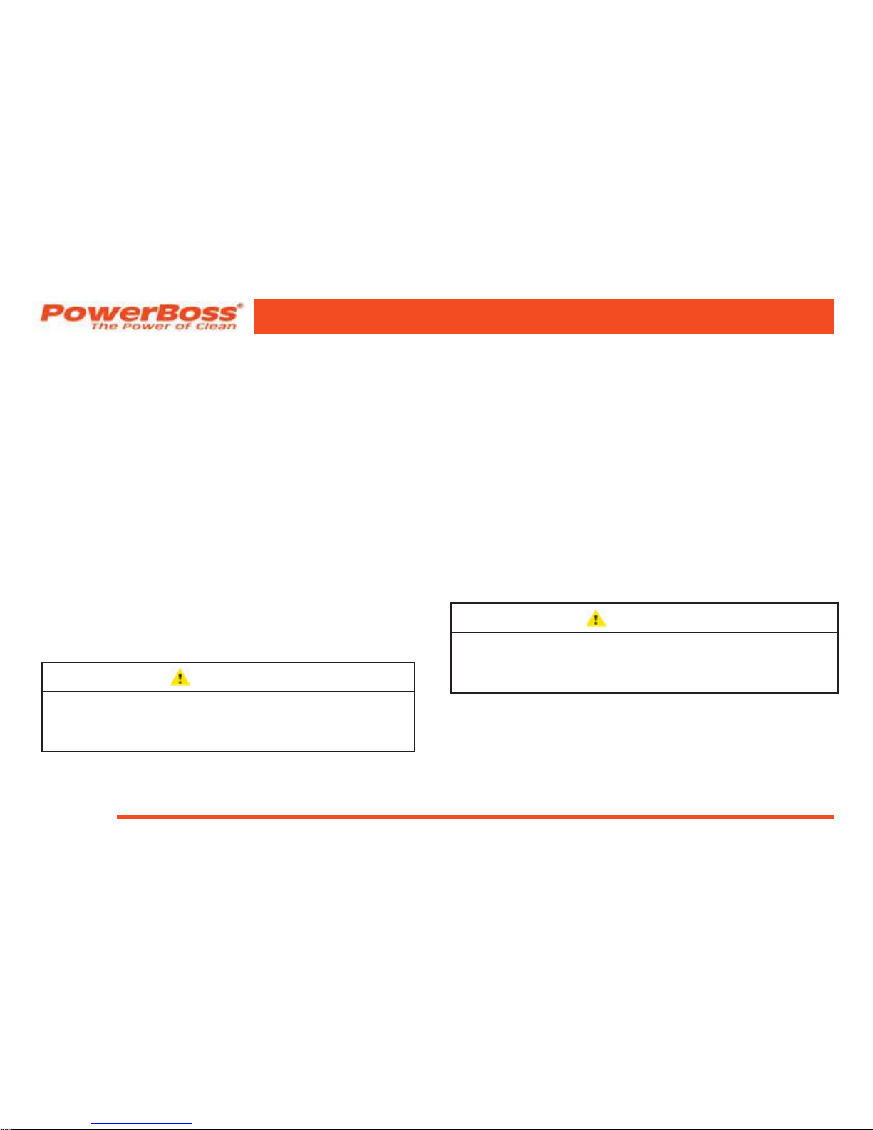
MACHINE OPERATION
IGNITION
SWITCH
DIRECTION
CONTROL
PEDAL
FUEL LEVEL
GAUGE
ENGINE OIL
PRESSURE
VOLTMETER
AMP GAUGE
ENGINE COOLANT
TEMPERATURE
GAUGE
HOUR
METER
SEAT
ADJUSTMENT
BRAKE
PEDAL
HORN
LIGHT
SWITCH
MURPHY
SWITCH
PARKING
BRAKE
THROTTLE
(DIESEL)
DIESEL ENGINE CONTROL AND INDICATOR LOCATIONS
GLOW PLUG
BUTTON
Page 28
PowerBoss, Inc. Copyright 2011
Commander T Series PB# 4100032 Rev. C 03/12
Page 28
MACHINE OPERATION
THROTTLE (GAS AND LP)
The throttle adjusts the engine speed from idle to the
operating speed. The LP and Gasoline models have a three
speed throttle switch with idle (turtle), run (rabbit) and fast
(tornado) selections.
• The throttle should be in the IDLE (turtle) position
when starting the engine and immediately before
shutdown.
• The throttle should be in the RUN (rabbit) position
during normal operation to ensure proper broom
speed.
CHECK ENGINE INDICATOR (GAS AND LP ONLY)
The indicator will illuminate in the event that the engine
water temperature rises above 226 degrees or oil pressure
drops below 7 psi. Shut down the unit and perform the
required service.
CAUTION
When the check engine indicator illuminates,
it indicates a service issue that requires
maintenance.
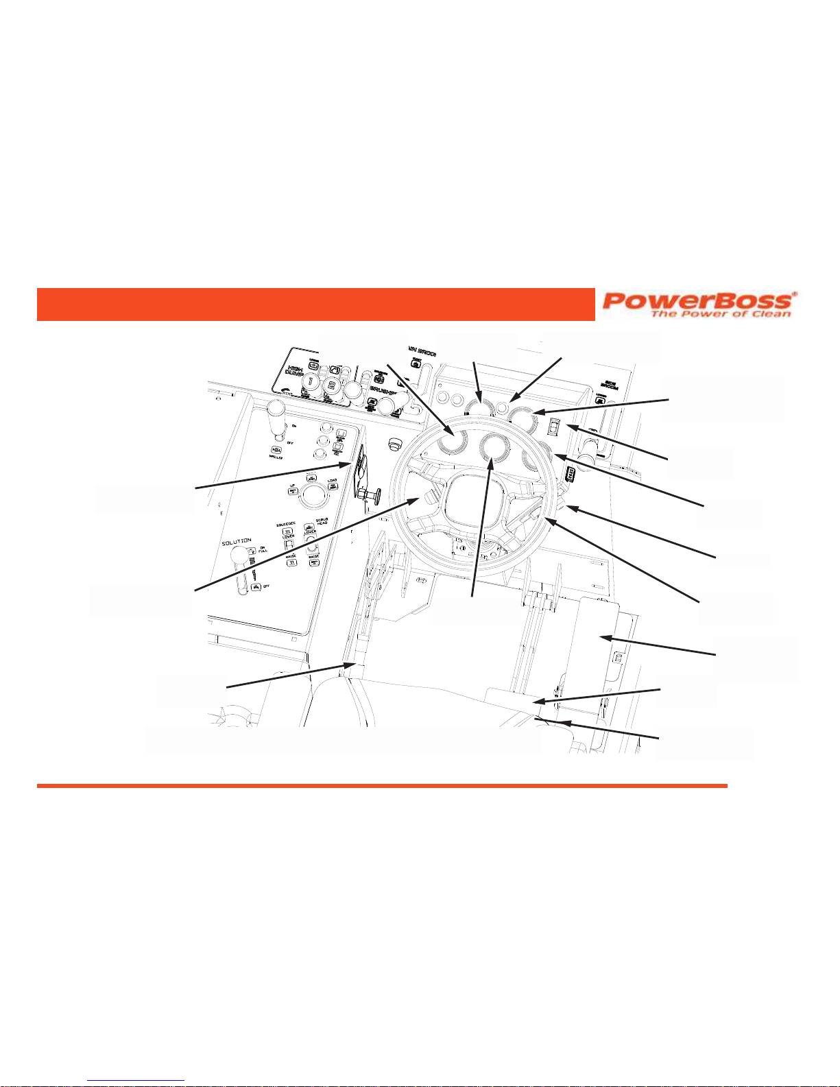
DIRECTIONAL CONTROL PEDAL
The directional control pedal controls the speed and direction
of the machine. It is also used for slowing the machine or
stopping.
• To propel the machine forward, apply pressure to the
front of the pedal, increasing pressure to increase
speed.
• To propel the machine backward, apply pressure to the
rear of the pedal.
• To slow or stop the machine, move the foot pedal into
neutral.
• For emergency stops, move the foot pedal past neutral
and into the opposite position.
CAUTION
Use for emergency stops only! Constant use of
this braking method may result in damage to the
drive components.
Page 29
Commander T Series PB# 4100032 Rev. C 03/12
PowerBoss, Inc. Copyright 2011
Page 29
MACHINE OPERATION
IGNITION
SWITCH
DIRECTION
CONTROL
PEDAL
FUEL LEVEL
GAUGE
ENGINE OIL
PRESSURE
VOLTMETER
AMP GAUGE
ENGINE COOLANT
TEMPERATURE
GAUGE
HOUR
METER
SEAT
ADJUSTMENT
BRAKE
PEDAL
HORN
LIGHT
SWITCH
THROTTLE
(GAS AND LP)
PARKING
BRAKE
CHECK ENGINE
INDICATOR
GAS AND LP ENGINE CONTROL AND INDICATOR LOCATIONS
FILTER SHAKER
BUTTON
Page 30

PowerBoss, Inc. Copyright 2011
Commander T Series PB# 4100032 Rev. C 03/12
Page 30
MACHINE OPERATION
SWEEPING / SCRUBBING CONTROLS AND
INDICATORS
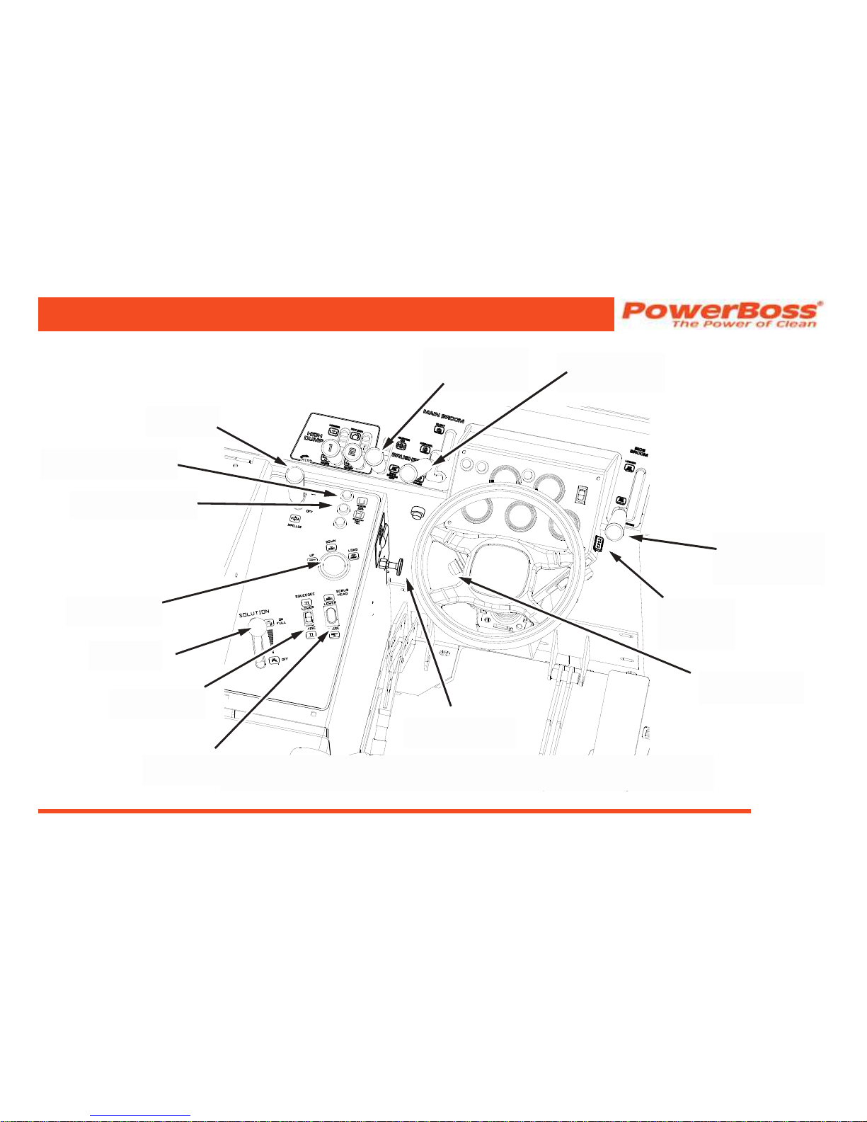
BROOM CONTROL LEVER
The broom control lever activates or deactivates the brooms
and scrub brushes. The lever is the second lever to the left of
the instrument panel. The lever has three control positions.
1. Push the lever forward to the brushes on position.
This activates the main broom, side broom, and
scrub brushes.
2. Pull the lever back to the side broom off position.
This will deactivate the side broom. The main broom
and scrub brushes will be remain activated.
3. Place the lever in the center of the slot. This will
deactivate the side broom, main broom and scrub
brushes.
NOTE: The main broom, side broom, and scrub
brushes may be raised or lowered
independently.
NOTE: The CE models are equipped with auto
broom shutoff which prevents brooms
from operating when hopper is raised.
MAIN BROOM HANDLE
The main broom handle to the immediate left of the
instrument panel, raises and lowers the main broom. The
handle has three control positions, raise, normal and oat.
1. Push the handle forward to the normal position for
typical sweeping applications.
2. Push the handle forward to the oat position for
surfaces that are extremely uneven.
NOTE: Frequent use of this position will reduce
the main broom life.
3. Pull the handle back to the raise position lift the
broom when not sweeping.
SIDE BROOM HANDLE
The side broom handle to the immediate right of the
instrument panel, raises and lowers the side broom.
• When not sweeping, the side broom should remain in
the RAISE position.
• To lower the side broom, push the handle forward to
the LOWER position.
Page 31
Commander T Series PB# 4100032 Rev. C 03/12
PowerBoss, Inc. Copyright 2011
Page 31
MACHINE OPERATION
MAIN BROOM
HANDLE
BROOM
CONTROL
LEVER
SIDE BROOM
HANDLE
IMPELLER STOP
CONTROL
IMPELLER
LEVER
SCRUB DECK
GAUGE
SOLUTION
LEVER
SQUEEGEE
SWITCH
SOLUTION TANK
EMPTY INDICATOR
RECOVERY TANK
FULL INDICATOR
SWEEPING AND SCRUBBING CONTROL AND INDICATOR LOCATIONS
FILTER SHAKER
BUTTON
HOPPER
UNLOCK
BUTTON
SCRUB HEAD
SWITCH
Page 32

PowerBoss, Inc. Copyright 2011
Commander T Series PB# 4100032 Rev.C 03/12
Page 32
MACHINE OPERATION
SCRUB HEAD SWITCH
The scrub head switch activates an actuator to raise and
lower the scrub deck. The scrub deck height can be adjusted
using the scrub head switch. The scrub deck gauge visually
indicates the deck height.
SCRUB DECK GAUGE
The scrub deck gauge indicates the position of the scrub
deck not the scrub deck pressure on the oor.
IMPELLER LEVER
The impeller lever activates and deactivates the vacuum
and is located in the upper left corner on the control panel.
Push the lever forward to the on position to activate the
vacuum. Pull the lever back to the off position to deactivate
the vacuum. Vacuum provides suction to the hopper and the
squeegee.
IMPELLER STOP CONTROL
The impeller stop control adjusts the amount of vacuum
supplied to the squeegee and hopper. Push the control in for
normal operation, with equal vacuum supplied to the hopper
and the squeegee. Pull out the control cable to limit the
vacuum supplied to the hopper and provide more vacuum to
the squeegee.
SQUEEGEE SWITCH
The squeegee switch raises and lowers the squeegee
mechanism. The squeegee height is mechanically adjustable
and will need adjustment as the squeegee blade wears.
SOLUTION LEVER
The solution lever controls the amount of solution applied to
the oor. Push the lever forward to begin the ow, adjusting
to the desired amount of ow. This is a gravity feed system
with a maximum ow of 3 gpm.
SOLUTION TANK EMPTY INDICATOR
The solution tank empty indicator is located on the front of
the left side control panel, and illuminates when the solution
tank is empty.
RECOVERY TANK FULL INDICATOR
The recovery tank full indicator is located on the front of the
left side control panel, and illuminates when the recovery
tank is full.
Page 33
Commander T Series PB# 4100032 Rev.C 03/12
PowerBoss, Inc. Copyright 2011
Page 33
MACHINE OPERATION
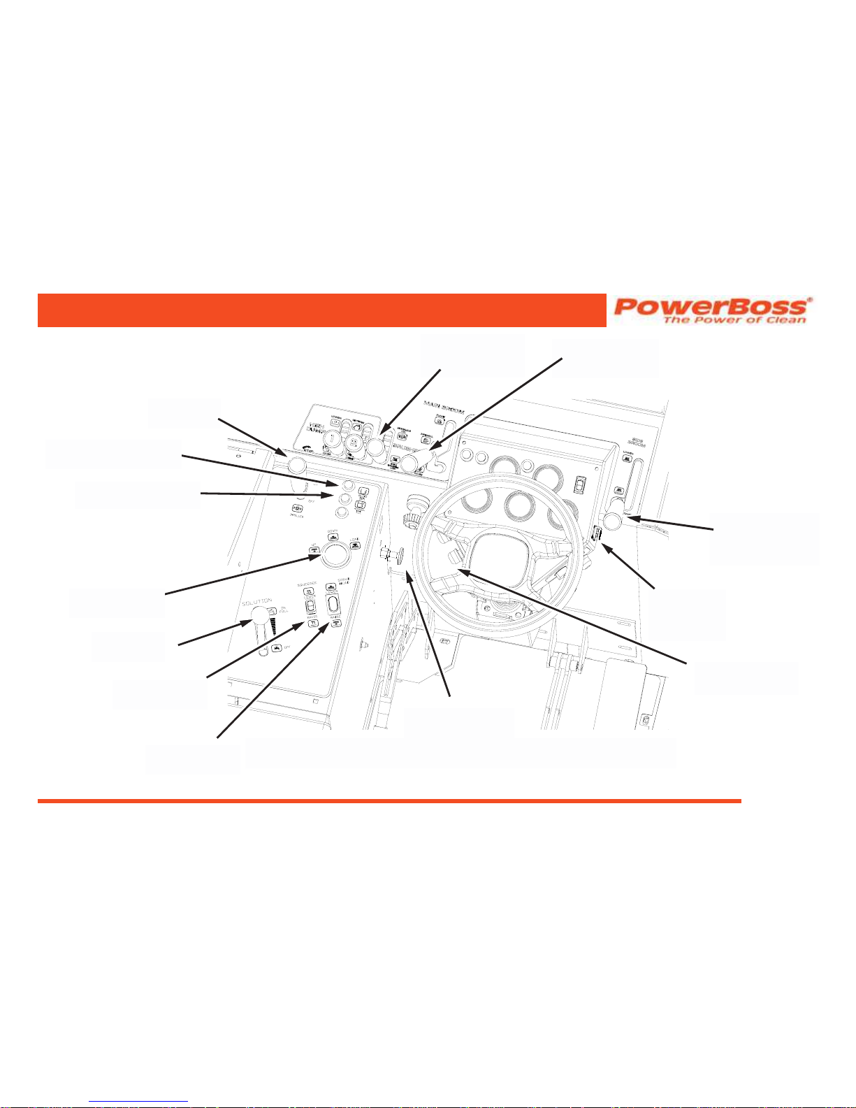
DIESEL ENGINE HOPPER CONTROL AND INDICATOR LOCATIONS
HOPPER
UNLOCK
BUTTON
SOLUTION TANK
EMPTY INDICATOR
RECOVERY TANK
FULL INDICATOR
SIDE BROOM
HANDLE
MAIN BROOM
HANDLE
BROOM
CONTROL
LEVER
IMPELLER
LEVER
IMPELLER STOP
CONTROL
SCRUB DECK
GAUGE
SOLUTION
LEVER
SQUEEGEE
SWITCH
FILTER SHAKER
BUTTON
SCRUB HEAD
SWITCH
Page 34

PowerBoss, Inc. Copyright 2011
Commander T Series PB# 4100032 Rev.C 03/12
Page 34
MACHINE OPERATION
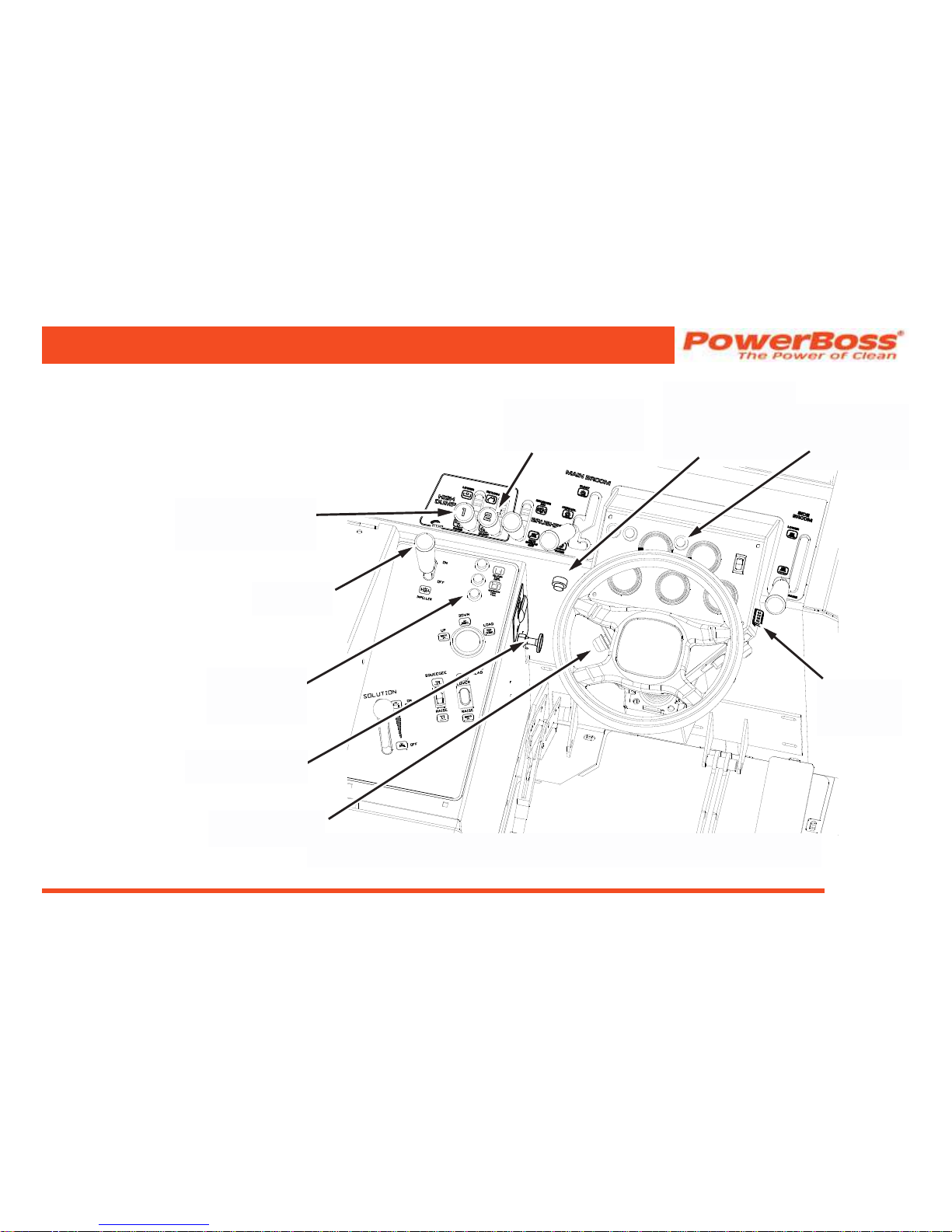
DEBRIS HOPPER DUMP CONTROLS
HIGH DUMP
The two far left levers on the front control panel are used to
raise the hopper to any height up to 60” (1.52 m) and dump
it.
WARNING
Never get beneath a raised hopper without the
safety arm in place.
Lever 1
Pull back on the lever 1 to raises the hopper, and release
the lever when you have reached the proper height. Push
forward to lower the hopper.
NOTE: The engine must be running to raise the
hopper, but does not have to be running to
lower the hopper.
Lever 2
Pull back on Lever 2 to rotate and dump the hopper. Push
forward to return the hopper to it original position.
NOTE: The engine must be running to dump and
return the hopper. The hopper must be
raised to rotate the hopper.
HOPPER UNLOCK BUTTON
If equipped the unlock hopper button must be pressed to
raise, lower, dump, and return the hopper. The commander
Europe model machines are equipped with a two handed
hopper operation.
ROTARY TRASH RELOCATOR (RTR™)
Rotary Trash Relocator (RTR™) is a standard feature on
high-dump models. Its purpose is to increase the holding
capacity of the debris hopper to make dumping the hopper
necessary less frequently.
HOPPER FILTER SHAKER BUTTON
This button is used to activate the lter shakers prior to
dumping or as needed during sweeping operation. It is
located to the left hand side of the instrument panel.
FIRE IN THE HOPPER INDICATOR (OPTIONAL)
The re in the hopper indicator illuminates when a re is
detected in the hopper.
Page 35
Commander T Series PB# 4100032 Rev.C 03/12
PowerBoss, Inc. Copyright 2011
Page 35
MACHINE OPERATION
CLOGGED FILTER INDICATOR (OPTIONAL)
The clogged lter indicator illuminates when the air ow
through the lter is restricted. The clogged ler indicator is
standard on CE models.
FIRE IN THE
HOPPER
INDICATOR
(GAS AND LP)
CLOGGED
FILTER
INDICATOR
IMPELLER STOP
CONTROL
FILTER SHAKER
BUTTON
IMPELLER
LEVER
GAS AND LP ENGINE HOPPER CONTROL AND INDICATOR LOCATIONS
HIGH DUMP RAISE
AND LOWER
LEVER 1
HIGH DUMP DUMP
AND RETURN
LEVER 2
HOPPER
UNLOCK
BUTTON
FIRE IN THE
HOPPER
INDICATOR
(DIESEL)
Page 36

PowerBoss, Inc. Copyright 2011
Commander T Series PB# 4100032 Rev.C 03/12
Page 36
MACHINE OPERATION
STARTING
Gasoline or LP Power Units
WARNING
Before starting the engine, sit in the operator’s
seat and make sure the parking brake is locked.
1. Make sure the directional control pedal is in the
neutral position.
2. Make sure the throttle is in the idle position.
3. Turn the ignition key to the start position (to the
right). When the engine starts, release the key.
CAUTION
If the engine fails to start, do not continue
cranking for more than ten seconds. Allow the
starter motor to cool between attempts.
4. Release the parking brake.
OPERATING PROCEDURES
PRE-OPERATION CHECKS
Prior to starting the engine, check the following:
1. Engine oil level
2. Engine coolant level
3. Fuel level
4. Hydraulic uid level
5. Brakes, steering and directional controls
6. The oor beneath the machine for signs of uid leaks
Fluid levels should be correct. Brakes, steering and
directional controls should be functioning properly. Hoses,
lines and tanks should be free of damage and leaks.
Page 37
Commander T Series PB# 4100032 Rev.C 03/12
PowerBoss, Inc. Copyright 2011
Page 37
MACHINE OPERATION
Diesel Power Units
WARNING
Before starting the engine, sit in the operator’s
seat and make sure the parking brake is locked.
1. Make sure the directional control pedal is in the
neutral position.
2. Make sure the throttle is in the idle position.
3. If the engine is cold, turn the ignition key to the IGN
position and press the Glow-plug switch for 15 to 20
seconds.
4. If equipped press and hold the Murphy switch, then
turn the ignition key clockwise to the start position.
When the engine starts, release the key and the
Murphy switch.
CAUTION
If the engine fails to start, do not continue
cranking for more than ten seconds. Allow the
starter motor to cool between attempts.
5. Release the parking brake.
TRAVELING FORWARD OR BACKWARDS
Forward
Apply pressure to the front of the directional control pedal,
increasing pressure to increase speed.
Reverse
Apply pressure to the rear of the pedal, increasing pressure
to increase speed.
WARNING
Exercise extreme caution when traveling across
or turning on grades. Do not exceed an 8º grade
SLOWING AND STOPPING
Allow the directional control pedal to move into neutral. The
machine will slow and coast to a stop.
Page 38

PowerBoss, Inc. Copyright 2011
Commander T Series PB# 4100032 Rev.C 03/12
Page 38
SWEEPING
1. Lower the main Broom, push the handle forward to
the NORMAL or FLOAT position.
NOTE: When sweeping extremely uneven oors,
position the main broom handle at FLOAT
on the handle slot.
2. If desired lower the side broom, push the handle
forward to the LOWER position.
3. Activate the broom motors:
• To activate both main and side brooms push the
broom control lever forward to the BRUSHES ON
position.
• To activate the main broom only pull the broom control
lever back to the SIDE BROOM OFF position.
4. Turn on the vacuum impeller, Push the impeller
lever forward to the on position.
5. Drive the machine over the area to be swept.
MACHINE OPERATION
EMPTYING THE HOPPER WITH HIGH DUMP
FEATURE
1. Drive the machine to the dumping area.
2. Use the directional control pedal to position the
machine so that the space between the machine
and the container or dumpster is adequate to raise
the hopper.
3. Reduce the engine speed.
4. Pull back Lever 1(press and hold the unlock hopper
button if equipped) to the RAISE position and hold
until the bottom of the hopper is high enough to clear
the top of the container.
WARNING
Never place your hands or other body parts
near the lift arms when the hopper is operating.
Page 39

Commander T Series PB# 4100032 Rev.C 03/12
PowerBoss, Inc. Copyright 2011
Page 39
5. Use the directional control pedal to slowly and
carefully move the machine forward until the hopper
is properly positioned to dump the debris into the
container.
WARNING
It is unsafe to travel an extended distance with
the hopper raised. Travel only the distance
necessary to position the hopper.
6. Shake the lters for 20-30 seconds. Pull back Lever 2
to the DUMP position to rotate the hopper forward and
empty the debris.
7. After the hopper empties, push Lever 2 forward (press
and hold the unlock hopper button if equipped) to the
RETURN position until the hopper rotates and stops.
8. Slowly back the machine away fro the dumpster
approximately 5 feet.
MACHINE OPERATION
9. Push Lever 1 forward (press and hold the unlock
hopper button if equipped) to the LOWER position
until the hopper stops.
Page 40

PowerBoss, Inc. Copyright 2011
Commander T Series PB# 4100032 Rev.C 03/12
Page 40
USING THE ROTARY TRASH RELOCATOR (RTR™)
1. Use the directional control pedal to stop the machine
on a level surface.
2. Move the throttle to the IDLE position.
NOTE: As you complete Steps three and four,
observe the two red lights labeled 1 and 2
in the upper left corner of the control pane.
• Light 1 illuminates when the hopper reaches the
minimum height required to use the RTR™ feature.
• Light 2 illuminates when the hopper reaches the
rotation stop point.
3. Pull back Lever 1 (press and hold the unlock hopper
button if equipped) to the RAISE position and hold
until Light 1 illuminates, then release.
WARNING
Make sure no one is in the area under or around
the hopper.
4. Pull back Lever 2 to the DUMP position (press and
hold the unlock hopper button if equipped) and hold
until Light 2 illuminates, then release.
NOTE: This rotates the hopper, causing the debris
to move from the rear entrance to the front
wall of the hopper. Rotating beyond this
point will cause the debris to be dumped
from the hopper.
5. Push Lever 2 forward (press and hold the unlock
hopper button if equipped) to the RETURN position
until the hopper rotates back and stops.
6. Push Lever 1 forward (press and hold the unlock
hopper button if equipped) to the LOWER position
until the hopper returns to the normal operating
position.
7. Move the throttle to the RUN position and resume
sweeping.
MACHINE OPERATION
Page 41

Commander T Series PB# 4100032 Rev.C 03/12
PowerBoss, Inc. Copyright 2011
Page 41
TO SHAKE THE FILTER
The unit may be equipped with an optional clogged lter
indicator. If illuminated shake the lter to remove excess
debris. If the clogged lter indicator illuminates excessively
clean the hopper lter.
1. Bring the machine to a complete stop.
2. Place the broom control lever in the OFF position.
3. Press and hold the lter shaker button for 20 to 30
seconds.
NOTE: The CE model is equipped with a timed
lter shaker, that will automatically shake
the lter for a predetermined time when
the button is pressed.
4. Place the broom control lever in the ON position and
resume sweeping.
FIRE IN THE HOPPER
The unit may be equipped with an optional re in the hopper
indicator. If illuminated a high temperature reading has been
detected in the hopper. Immediately turn impeller off and
shut down the unit. Extinguish the re using appropriate
methods.
WARNING
If a re is detected do not open the lid without
protective gear, re may are up. Use re
protective gear and re extinguisher when
extinguishing the re.
MACHINE OPERATION
Page 42

PowerBoss, Inc. Copyright 2011
Commander T Series PB# 4100032 Rev.C 03/12
Page 42
SCRUBBING
Operating the Scrub Brushes
1. Activate the scrub brushes by putting the broom
control lever in the ON position.
2. Lower the scrubhead to the oor with the scrubhead
rocker switch located on the console left of the
operator. Press to “Lower” Position. Scrubhead is
raised by same switch. Press to “Raise” position.
NOTE: The scrubhead gauge is a visual indication
of the scrub deck position and not the
amount of pressure on the oor.
Starting Solution Flow
3. Push the solution lever forward until the desired
amount of solution is applied.
NOTE: This is a gravity feed system. Maximum
ow is 3 gpm.
4. Turn on the vacuum impeller, Push the impeller
lever forward to the on position.
Lower The Squeegee
5. Press the squeegee switch to the Lower Position.
6. Drive the machine over the area to be scrubbed.
MACHINE OPERATION
Page 43
Commander T Series PB# 4100032 Rev.C 03/12
PowerBoss, Inc. Copyright 2011
Page 43
FILLING THE SOLUTION TANK
CAUTION
Never use detergents or cleaners that are
ammable or combustible. Always wear safety
glasses and protective clothing when using
chemicals of any kind.
It is recommended to use PowerBoss chemicals
which are specially formulated for use in power
scrubbers.
1. Park the machine on a level area and lock the
parking brake.
2. Make sure the solution delivery valve is closed via
the solution lever.
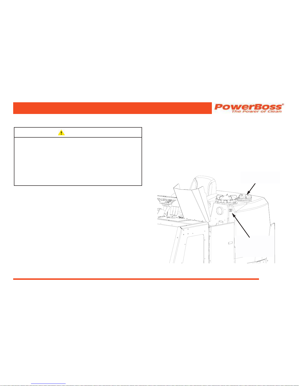
3. Open the top door of the machine and remove the
plug @ the Auto ll Assembly. Connect a garden
hose to the AutoFill Assembly. Turn on faucet for
clean water solution. The water will shut off when the
proper level is achieved. Disconnect garden hose
replace the plug @ auto ll connector and close top
door.
MACHINE OPERATION
SOLUTION TANK
AUTO FILL
ASSEMBLY
SOLUTION TANK
6” FILL CAP
or
Unscrew the smallest (6 inch) cap located on the top
of the solution tank. Fill the tank with cleaning water
solution. When the tank is full, close the door and
replace the cap.
Page 44
PowerBoss, Inc. Copyright 2011
Commander T Series PB# 4100032 Rev.C 03/12
Page 44
DRAINING THE RECOVERY TANK
1. Park the machine on a level surface at an approved
drainage site with the left rear of the machine beside
the drain access.
2. Engage the parking brake.
3. Turn the machine OFF.
4. Open the left scrubhead access door.
MACHINE OPERATION
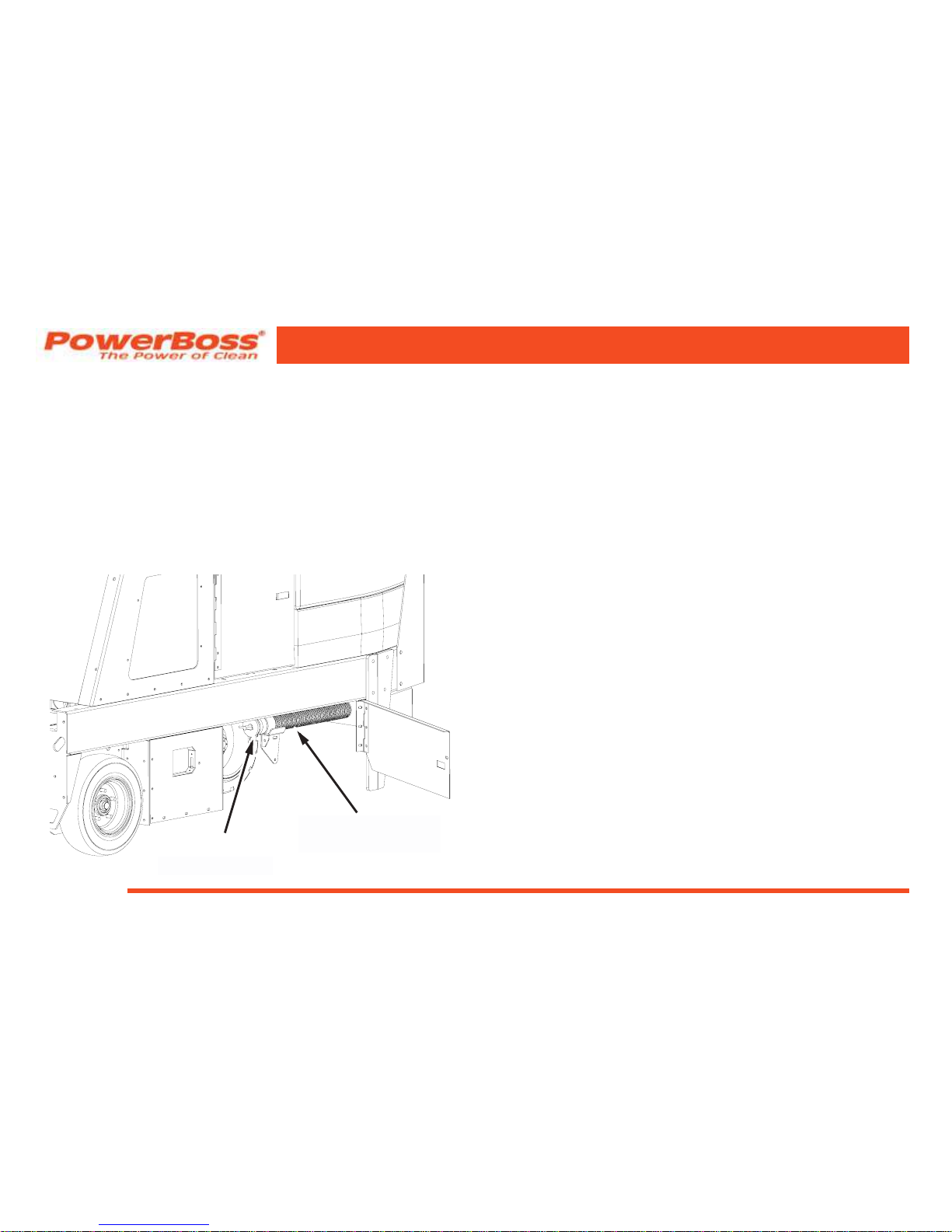
5. Remove the exible drain hose from its storage
hook. Pull out the drain hose for the required reach
to the access.
6. Place the end of the drain hose on or in the
approved drain access.
7. Loosen and remove the drain plug.
8. Drain the tank completely and reinstall the plug.
9. Reposition the drain hose on its storage hook.
CLEANING THE RECOVERY TANK
NOTE: The Recovery Tank Should Be Cleaned
After Every Shift.
1. Position the machine at an approved drain area.
2. Engage the parking brake.
3. Shut off the machine.
4. Remove the two 9” access caps at the rear of the
unit.
5. Remove the drain hose and position it over the
approved drain opening.
6. Loosen and remove the drain plug.
DRAIN PLUG
RECOVERY TANK
DRAIN HOSE
Page 45

Commander T Series PB# 4100032 Rev.C 03/12
PowerBoss, Inc. Copyright 2011
Page 45
MACHINE OPERATION
RECOVERY TANK
9” ACCESS CAPS
SOLUTION TANK
6” FILL CAP
RECOVERY TANK
9” ACCESS CAP
SOLUTION TANK
6” ACCESS CAP
7. Spray the tank with clean water, ushing all sludge
out of the access ports.
8. Remove the ball and oat. Rinse and reinstall.
9. Drain the tank completely and reinstall the drain
plug.
10. Return the drain hose to the storage hook at the left
side scrub door area beneath the oor pan.
11. Replace the 9” access caps removed in step four.
SQUEEGEE WAND (OPTION)
This attachment allows the operator to vacuum spills
and standing water in areas which the machine cannot
maneuver.
1. Remove the hose from the squeegee tool.
2. Attach the adapter to the squeegee hose.
3. Connect the squeegee wand to the adapter.
4. Turn on impeller
5. Set the engine at a high speed and vacuum the
spills or standing water.
Page 46

PowerBoss, Inc. Copyright 2011
Commander T Series PB# 4100032 Rev.C 03/12
Page 46
Pushing the Machine
Push the machine from the front or rear using the bumpers only.
NOTE: The propulsion pump is equipped with a
tow valve located on the top of the pump.
To engage the tow valve:
1. Turn the at-sided shaft at the top of the pump 90°.
2. Valve must be returned to its original position for
normal operation the machine.
ATTENTION!
Do not tow or push the machine a distance of
more than .5 miles (.80 kilometers) or faster than
one mile per hour (1.61 km). Exceeding these
restrictions may cause damage to the hydraulic
system. If towing will exceed the above
restrictions, the rear wheel must be raised or
supported by a dolly.
MACHINE OPERATION
BLOWER (OPTION)
The blower can move debris from hard-to-reach areas into
he path of the sweeper using forced air. To operate; With
unit running @ high Rpm’s and impeller on, take the wand
in hand and pull the blower control knob out. Aim at desired
debris. Return wand and knob to normal position when
done.
TRANSPORTING THE MACHINE
Using a Trailer or Transport Vehicle
1. Position the machine on the transport vehicle or
trailer and apply the parking brake.
2. Chain the machine down using the two (2) tie-down
holes in the frame in front of both front wheels and
one (1) @ the rear center of the frame extension
bumper.
NOTE: Attach Tie Downs To The Frame &
Extension Bumper Only!
Page 47

Commander T Series PB# 4100032 Rev.C 03/12
PowerBoss, Inc. Copyright 2011
Page 47
PREVENTATIVE MAINTENANCE
INTRODUCTION
Regular maintenance on your sweeper scrubber results in
better cleaning, faster cleaning and a prolonged service life
for the equipment and components. This section contains the
following information to help you give your sweeper scrubber
the maintenance attention it requires:
• A Scheduled Maintenance Chart
• Preventative Maintenance Instructions for Required
Scheduled Maintenance Tasks
Because it is extremely important to your safety, you will see
the following WARNING repeated throughout this section:
WARNING
Never attempt to perform any service on the
equipment or components until the engine is
OFF, the parking brake is LOCKED, and the
wheels are CHOCKED.
PREVENTATIVE MAINTENANCE
Page 48

PowerBoss, Inc. Copyright 2011
Commander T Series PB# 4100032 Rev.C 03/12
Page 48
SCHEDULED MAINTENANCE CHART
FREQUENCY (IN HOURS) SERVICE
(BY MAINTENANCE AREA)
DAILY 50 100 200 500
ENGINE
X Pressure wash engine
NOTE: For additional maintenance requirements, refer to the engine manual.
AIR INTAKE SYSTEM
X Empty rubber dust cup of air lter element.
X Check air lter indicator
X Clean air lter. NOTE: Clean more often in dusty conditions.
X Replace air lter.
ELECTRICAL SYSTEM
X Clean battery top.
COOLANT SYSTEM
X Check coolant level and ll as needed.
X Inspect radiator ns and clean as needed.
X Blow out radiator ns.
X Drain and ush the coolant system
PREVENTATIVE MAINTENANCE
Page 49

Commander T Series PB# 4100032 Rev.C 03/12
PowerBoss, Inc. Copyright 2011
Page 49
SCHEDULED MAINTENANCE CHART
FREQUENCY (IN HOURS) SERVICE
(BY MAINTENANCE AREA)
DAILY 50 100 200 500
LUBRICATION POINTS
X Steering Cylinder (2 ttings) Lubricate type - grease
X Steering Fork Assembly (3 ttings) - grease
X Dump Hopper Lift Arm Mounts (4 ttings) Lubricate type - grease
X Hood Latches & Hinges Lubricate type - oil
IMPELLER
X Check for hydraulic uid leaks.
HYDRAULIC SYSTEM
X Check hydraulic reservoir and ll as needed.
X Replace breather cap lter element.
X Replace hydraulic uid and lter
X Check functioning of directional control pedal and adjust as needed.
X Clean hydraulic uid strainer in reservoir.
X Inspect hydraulic oil cooler ns and clean as needed (if so equipped).
X Blow out hydraulic oil cooler ns with compressed air (if so equipped).
PREVENTATIVE MAINTENANCE
Page 50

PowerBoss, Inc. Copyright 2011
Commander T Series PB# 4100032 Rev.C 03/12
Page 50
PREVENTATIVE MAINTENANCE
SCHEDULED MAINTENANCE CHART
FREQUENCY (IN HOURS) SERVICE
(BY MAINTENANCE AREA)
DAILY 50 100 200 500
SWEEPING COMPONENTS
X Inspect brooms for wear and remove strings and debris from bristles and drive assembly.
X Inspect broom skirts for wear and adjust or replace as needed.
X Rotate main broom end-to-end.
X Perform main broom adjustment test and adjust as needed.
X Inspect the side broom for wear and adjust as needed.
Replace main and side brooms as needed:
Main Broom needs to be replaced if bristles are 1” in length or less.
Side Broom needs to be replaced if bristles are 3” in length or less.
HOPPER
X Check hopper lters and clean or replace as needed.
X Inspect the hopper aps for wear or damage and replace as needed.
X Inspect hopper side and frame seals for wear or damage. Adjust or replace as needed.
STEERING
X Lubricate steering cylinder rod ends.
X Lubricate steering fork assembly.
X Check for leaks.
Page 51

Commander T Series PB# 4100032 Rev.C 03/12
PowerBoss, Inc. Copyright 2011
Page 51
SCHEDULED MAINTENANCE CHART
FREQUENCY (IN HOURS) SERVICE
(BY MAINTENANCE AREA)
DAILY 50 100 200 500
PARKING BRAKE
X Check for proper functioning and adjust as needed.
TANKS
X Check squeegee tool and vacuum hose for clogs.
WHEELS AND TIRES
X Visually inspect for wear and damage. Repair or replace as needed.
X Check and tighten lug nuts. (torque to 100 ft.-lbs)
MISCELLANEOUS
X Inspect latches and hinges. Tighten and lubricate as needed.
X Check anti-static drag chain on rear wall of broom chamber for damage or excessive wear.
Replace as needed.
X Check side broom lift cable and lift cable for wear.
SCRUB AND WATER PICK-UP COMPONENTS
X Inspect disc scrub brushes and replace as needed. Maximum wear = ½”
X Inspect squeegee are and adjust as needed.
X Check the rear squeegee blade for wear. (Turn or replace as needed.)
PREVENTATIVE MAINTENANCE
Page 52

PowerBoss, Inc. Copyright 2011
Commander T Series PB# 4100032 Rev.C 03/12
Page 52
PREVENTATIVE MAINTENANCE
INSTRUCTIONS
ENGINE
Maintenance requirements and service instructions for your
sweeper scrubber engine are outlined in the following parts
of this Maintenance Section:
• Air Intake System
• Electrical System
• Fuel System
• Coolant System
• Lubrication System
All basic maintenance tasks are listed with their
recommended frequencies on the Planned Maintenance
Chart in this manual. Important additional maintenance
requirements and instructions are explained in the engine
manual which comes with your machine.
WARNING
Never attempt to perform any service on the
equipment or components until the engine if
OFF, the parking brake is LOCKED, and the
wheels are CHOCKED.
PREVENTATIVE MAINTENANCE
Air Intake System
Check Air Filter Service Indicator
The air lter service indicator shows when to change the
air lter element. Check the indicator on a daily basis. The
red indicator gradually becomes visible as the air lter
elements load with dirt. It is not necessary to change the air
lter elements until the red indicator reaches the top of the
service indicator and locks into position.
1. Lift engine cover.
2. Inspect air lter service indicator
NOTE: The indicator may return to the not visible
position when the engine is shut off. To
check, reset indicator and turn on the
engine, if it locks in visible position again
clean or change element.
Page 53
Commander T Series PB# 4100032 Rev.C 03/12
PowerBoss, Inc. Copyright 2011
Page 53
PREVENTATIVE MAINTENANCE
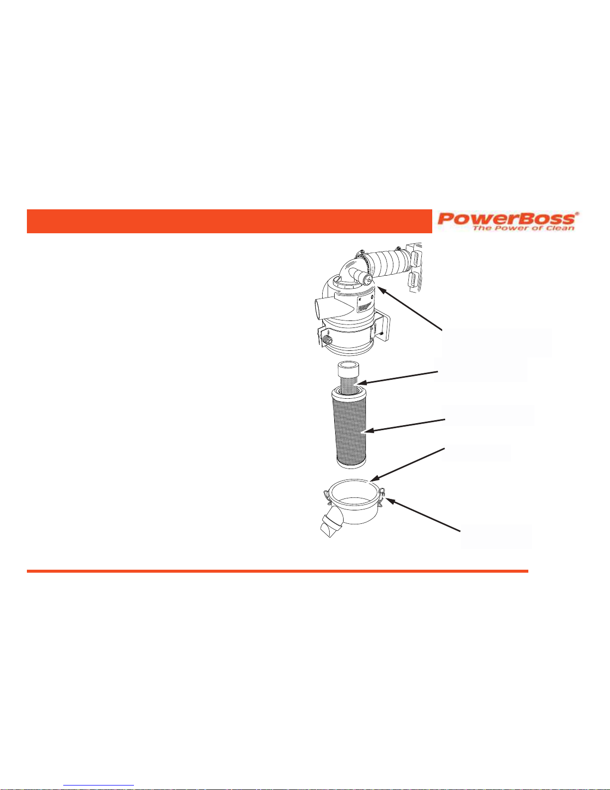
Air Filter Element Removal
1. Turn off the engine and set the parking brake.
2. Lift the engine cover.
3. Locate the air lter and loosen the retaining clamp.
4. Remove the dust cup.
5. Pull the rubber plug out of the dust cup and empty
the contents.
NOTE: The Diesel engine has a wing nut holding the air
lter element in place, remove the wing nut rst.
6. Pull the air lter elements out of its housing.
AIR FILTER
ELEMENT INNER
AIR FILTER SERVICE
INDICATOR
RETAINING
CLAMPS
DUST CAP
AIR FILTER
ELEMENT OUTER
Page 54

PowerBoss, Inc. Copyright 2011
Commander T Series PB# 4100032 Rev.C 03/12
Page 54
Air Filter Cleaning
1. Once you have removed the air lter elements,
empty the dust cup and clean the interior of the air
lter housing.
2. Use an air hose to blow out the air lter elements.
Air pressure should be 100 psi or less.
Air Filter Inspection
1. After you clean the air lter elements, check the
elements for holes by passing a light bulb inside it.
PREVENTATIVE MAINTENANCE
Air Filter Installation
1. Wipe out the air cleaner housing with a damp cloth.
Be sure all dirt is removed.
2. Install the cleaned replacement lter elements so
that the ns are at the far end of the
housing. Be careful not to damage the ns.
3. Replace the rubber plug in the dust cup.
4. Replace dust cup, being sure embossed word “top”
on cup is positioned correctly (up).
5. Tighten the ring clamp or retaining clips.
6. Check the condition of intake hoses and clamps.
Close engine cover.
Page 55

Commander T Series PB# 4100032 Rev.C 03/12
PowerBoss, Inc. Copyright 2011
Page 55
ELECTRICAL SYSTEM
Battery Cleaning
1. Combine baking soda and water in a strong
solution.
2. Brush the solution over the battery top, including
terminals and cable clamps. Make sure the solution
does not enter the battery.
3. Using a wire brush, clean the terminal posts and
cable clamps.
4. Apply a thin coating of petroleum jelly to the
terminals and cable clamps.
Battery Replacement
CAUTION
Remove the negative battery cable before you
remove the positive battery cable. This is done
to prevent accidental electrical shorting which
can result in personal injury.
1. Disconnect the negative (-) cable and then the
positive (+) cable.
2. Remove the battery.
3. Install the new battery.
4. Connect the positive (+) battery cable rst, then the
negative (-) cable.
PREVENTATIVE MAINTENANCE
Page 56
PowerBoss, Inc. Copyright 2011
Commander T Series PB# 4100032 Rev.C 03/12
Page 56
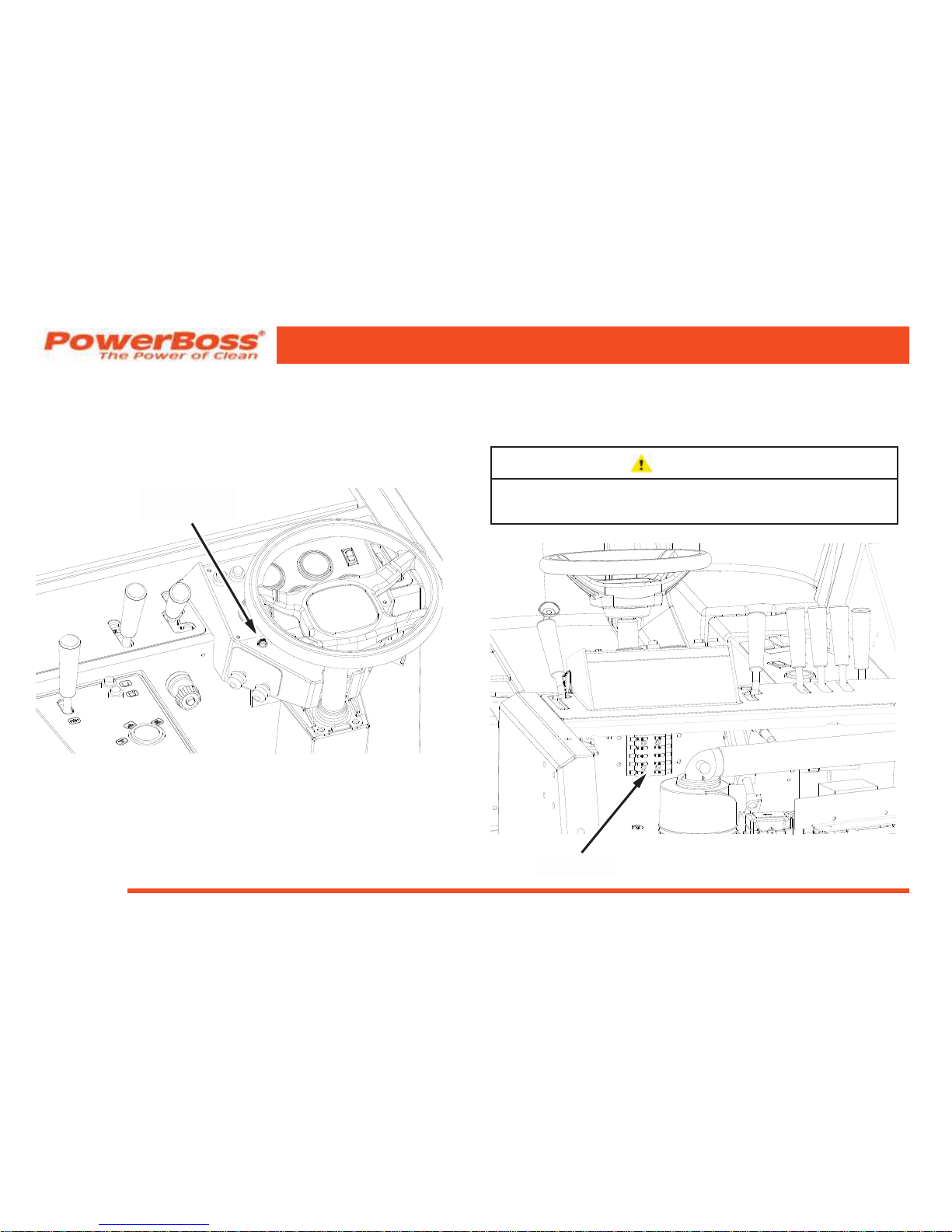
Circuit Breaker
If a circuit breaker trips, it can be reset by pressing the reset
button in the center of the breaker. (The circuit breakers are
located on the instrument panel below the steering wheel).
Fuses
Fuses are located in the fuse panel behind the hopper on
the re wall upper right corner when facing the unit
CAUTION
Safety Arm Must Be Engaged When Checking
These Fuses
PREVENTATIVE MAINTENANCE
CIRCUIT
BREAKER
FUSES
Page 57
Commander T Series PB# 4100032 Rev.C 03/12
PowerBoss, Inc. Copyright 2011
Page 57
FUEL SYSTEM
WARNING
Never attempt to perform any service on the
equipment or components until the engine is
OFF, the parking brake is LOCKED, and the
wheels are CHOCKED.
WARNING
Never operate an LP powered sweeper
when any component in the fuel system is
malfunctioning or leaking.
WARNING
Never bypass safety components unless you
are testing them.
WARNING
Replace any defective safety components
before operation the sweeper.
WARNING
During repair or servicing of the fuel system,
work in a properly ventilated area and do not
smoke or allow an open ame near the fuel
system.
WARNING
When disconnecting the tank coupling, always
wear gloves. LP fuel can freeze bare hands.
WARNING
Under no circumstances should the fuel lter
lock be bypassed, except when testing. After
testing, always reconnect lock. Bypassing the
fuel lter lock after testing creates a potential
re hazard.
Tier װ compliant fuel system Refer to P.S.I Service Manual
PREVENTATIVE MAINTENANCE
Page 58

PowerBoss, Inc. Copyright 2011
Commander T Series PB# 4100032 Rev.C 03/12
Page 58
COOLANT SYSTEM
Blowing Out Radiator Fins
NOTE: Make sure radiator is cool before blowing
out the radiator ns with compressed air.
Use maximum compressed air pressure of
100 p.s.i. to blow out radiator ns with.
Reverse Flow Flushing
1. At the engine, disconnect the hoses.
2. Make sure the radiator cap is on tight.
3. Using a hose clamp, attach a ushing gun onto the
lower hose.
4. Turn on the water and ll the radiator.
5. To keep from damaging the radiator, apply air
pressure slowly and carefully.
6. Shut off the air pressure, rell the radiator with
water, and reapply the air pressure. You will need
to repeat these steps until water ushed from the
radiator runs out clear.
7. Inspect and clean the radiator cap.
8. Inspect and reconnect the hoses.
9. Rell the radiator with coolant.
NOTE: Use a 50/50 mixture of water and an anti-
freeze with an ethylene glycol base.
ATTENTION!
Plain Water, Alcohol or Methanol base antifreeze
is not recommended for use in the cooling
system at anytime!
PREVENTATIVE MAINTENANCE
Page 59
Commander T Series PB# 4100032 Rev.C 03/12
PowerBoss, Inc. Copyright 2011
Page 59
LUBRICATION
Gasoline and LP Engines: Use any SF or SG rated
oil meeting API specications and suited to seasonal
temperatures.
Refer to the Engine Manufacturer’s Operator Manual for
these specications.
Changing Engine Oil
1. Place a drain pan under the lowest end of the
engine.
2. Remove the drain plug and allow the oil to drain into
the pan.
3. Remove the used oil lter and replace with a new
one.
4. Dispose of the oil and oil lter in an approved
manner.
5. Remove the engine oil cap, add oil in the amounts
listed in the engine manual, then secure the cap.
LUBRICATION POINTS
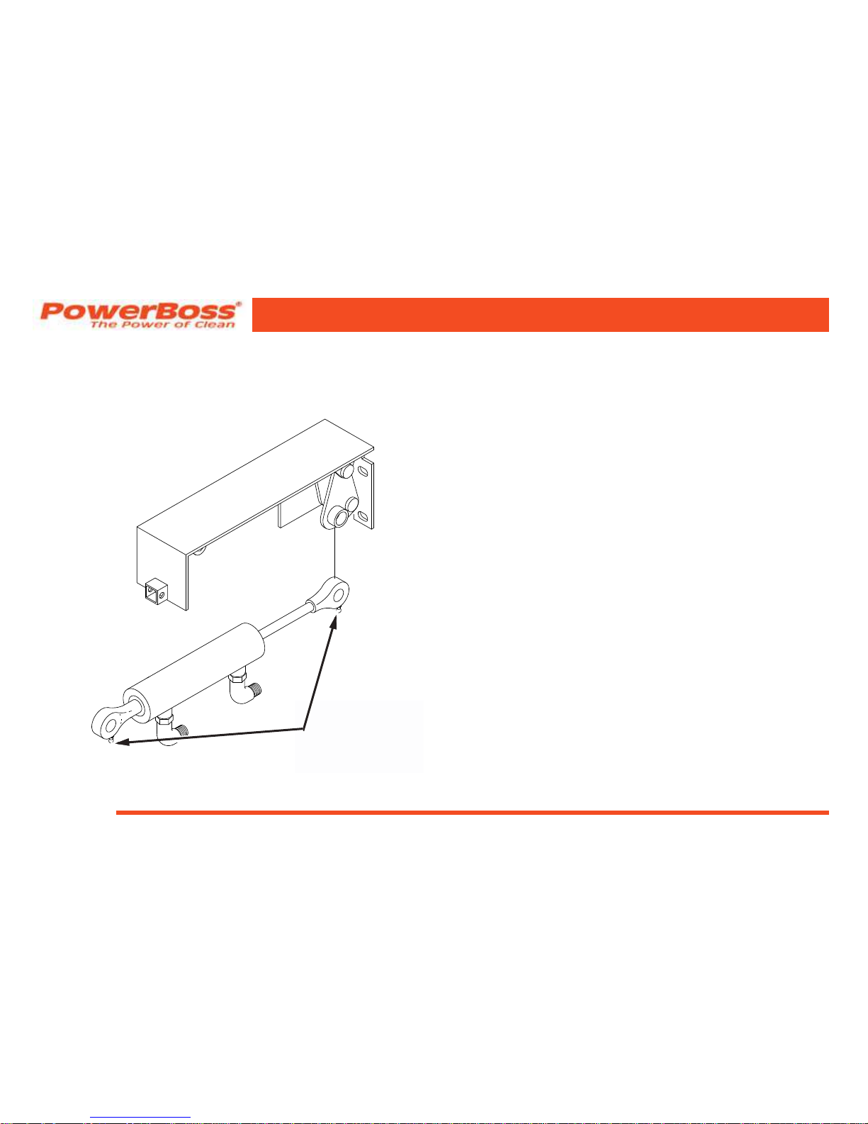
Steering Fork Assembly and Steering Link Ball
Joints
The steering fork assembly and steering link ball joints must
be lubricated every 500 hours with grease, The steering fork
assembly has 1 grease point and the steering link has two
ball joint with one grease point each.
PREVENTATIVE MAINTENANCE
STEERING LINK
BALL JOINT
LUBRICATION
POINTS
STEERING FORK
ASSEMBLY
LUBRICATION POINT
Page 60
PowerBoss, Inc. Copyright 2011
Commander T Series PB# 4100032 Rev.C 03/12
Page 60
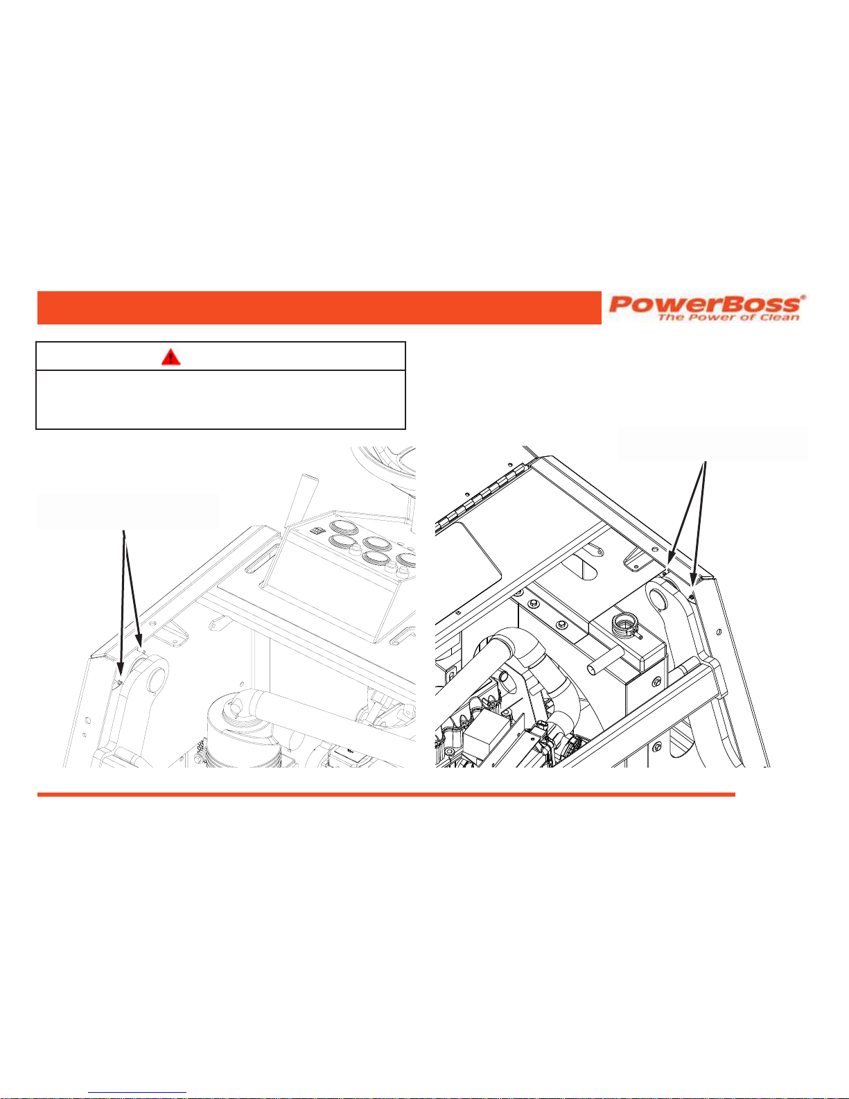
Steering Cylinder
The steering cylinder must be lubricated every 500 hours
with grease. There are two lubrication points, one each end
of the cylinder.
Latches & Hinges
The hinges and latches of all doors and covers should be
lubricated with oil every 500 hours. There are numerous
hinges and latches, make sure to lubricate all of the
following:
• Engine cover
• Top Gas Tank Cover
• Side Door and Latch
• Main Broom Doors
• Scrub Doors and Latches
• Seat Hinge
Hopper Lift Arm Mounts
The dump hopper lift arm mounts must be lubricated every
100 hours with grease, There are two lubrication points on
each mount.
1. Park the machine on a level surface.
2. Raise the hopper and engage the safety arm
PREVENTATIVE MAINTENANCE
STEERING
CYLINDER
LUBRICATION
POINTS
Page 61
Commander T Series PB# 4100032 Rev.C 03/12
PowerBoss, Inc. Copyright 2011
Page 61
WARNING
Do not rely upon the hydraulic cylinders to keep
the hopper raised. Always engage the safety arm
before servicing the hopper.
4. Shut off the engine and engage the parking brake.
5. Locate and grease the hopper lift arm lubrication
points.
PREVENTATIVE MAINTENANCE
HOPPER LIFT ARM MOUNT
LUBRICATION POINTS
HOPPER LIFT ARM MOUNT
LUBRICATION POINTS
Page 62

PowerBoss, Inc. Copyright 2011
Commander T Series PB# 4100032 Rev.C 03/12
Page 62
HYDRAULICS SYSTEM
Filling The Fluid Reservoir
NOTE: The reservoir is located inside the machine
and is accessible through the top side door.
1. When the machine is cool remove the ll cap and
check the dipstick at attached to the ll cap. The
hydraulic uid should be at the notch on the dipstick.
CAUTION
DO NOT OVERFILL! DO NOT USE
TRANSMISSION FLUID. HYDRAULIC OIL
MUST MEET THE SPECIFICATIONS LISTED TO
ENSURE PROPER PERFORMANCE.
Hydraulic Fluid Viscosity Specications
SUS @ 100° F 510-560
SUS @ 210° F 78-84
Exxon® XD-3™ 15W-40 or equal.
2. If the uid level is not acceptable, add hydraulic uid.
PREVENTATIVE MAINTENANCE
Maintaining Hydraulic Oil Cooler Efciency
Your machine is equipped with a hydraulic oil cooler, it is
integrated with the radiator and utilizes exhausted radiator air
from the engine fan to cool the hydraulic uid. To maintain its
efciency, periodically blow out the radiator & oil cooler ns
with compressed air. 100 p.s.i. is maximum
Changing The Hydraulic Fluid
1. Turn off the engine and engage the parking brake.
2. Place a drain pan on the oor below the reservoir.
3. Remove the hose and tting located on the bottom
rear of the reservoir and allow the uid to drain.
4. Discard the uid in an approved manner, then replace
and reinstall the hose and tting.
5. Remove the ller / breather cap located on top of the
reservoir and ll the reservoir with approved hydraulic
uid.
Page 63

Commander T Series PB# 4100032 Rev.C 03/12
PowerBoss, Inc. Copyright 2011
Page 63
PREVENTATIVE MAINTENANCE
NOTE: Ten (10) gallons (US) of uid are required.
6. Check the dipstick to ensure the proper level is
achieved.
7. Install the ller / breather cap assembly.
8. Check the drain plug for leakage.
Changing The Hydraulic Fluid Filter
1. Turn off the engine and engage the parking brake.
2. Unscrew the oil lter cartridge from the mount and
discard in an approved manner.
3. Apply a thin coating of uid to the seal of a new
lter element.
4. Thread onto the mount and hand tighten.
5. Tighten an additional one-half turn beyond hand
tight.
NOTE: Do not over tighten.
6. Start the machine, shut it off, then check for
leakage.
Page 64

PowerBoss, Inc. Copyright 2011
Commander T Series PB# 4100032 Rev.C 03/12
Page 64
SWEEP COMPONENTS
Broom Door Flap Inspection
NOTE: Perform this inspection when the machine
is parked on a level surface.
1. Turn the machine off and lock the parking brake.
2. Inspect broom door aps for wear and damage. Flap
clearance should be ⅛” (3.18 mm) above the oor.
3. Worn and damaged aps should be replaced
immediately to maintain proper dust control.
Broom Door Flap Replacement and Adjustment
The aps are attached to the broom doors by a retainer bar,
hex bolts and nuts. To remove the aps, remove the nuts,
bolts and retainer bar. To adjust the aps, loosen the nuts
and bolts, slide the ap up or down as needed. Retighten
the nuts and bolts.
PREVENTATIVE MAINTENANCE
Page 65
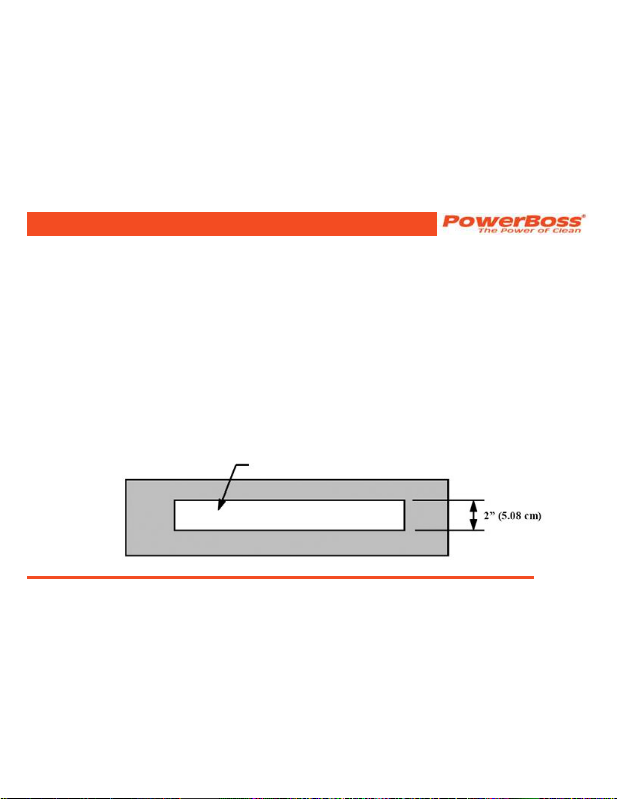
Commander T Series PB# 4100032 Rev.C 03/12
PowerBoss, Inc. Copyright 2011
Page 65
Main Broom Pattern Check
NOTE: Perform this adjustment on a at, smooth
test surface. You may spread baby powder
on the test surface area to make the
broom pattern more visible.
1. Drive the machine onto the test surface.
2. Set the parking brake and put the brush switch in
the on position.
3. Push the broom control lever to the ON position to
activate the broom motor and open the throttle to
the “rabbit” or “tornado” position.
4. Depress Fwd/Rev pedal just enough to turn on
brush motor.
5. Allow about 45 seconds for the broom to operate,
then deactivate the broom motor and raise the
broom.
NOTE: Test time will vary according to the test
surface used.
6. Drive the machine clear of the test site.
7. Examine the polished pattern made by the broom
on the test area.
NOTE: A rectangular shape the length of the
main broom, 2” (5.08 cm) wide, indicates
the main broom is properly adjusted. A
pattern smaller then 2” (5.08 cm) indicates
need for lower adjustment. A pattern wider
than 2” (5.08 cm) indicates a need for
higher adjustment. If pattern is tapered
from end to end instead of rectangular,
see Taper Adjustment on the next page.
PREVENTATIVE MAINTENANCE
Main Broom Test Pattern
Page 66

PowerBoss, Inc. Copyright 2011
Commander T Series PB# 4100032 Rev.C 03/12
Page 66
Main Broom Height Adjustment
1. Turn the machine off and lock the parking brake.
2. Position the main broom lever in the NORMAL
position.
NOTE: The adjustment knob is located in the
engine compartment on the broom rod
pivot.
3. Turn the broom adjusting knob clockwise one-eighth
turn to free the wing nut.
4. Turn the wing nut counter-clockwise to allow space
for adjustment.
5. Make a lower or higher adjustment with the knob as
required.
6. Retighten the wing nut.
7. Repeat the broom adjustment test to see that the
broom is properly adjusted.
PREVENTATIVE MAINTENANCE
Page 67
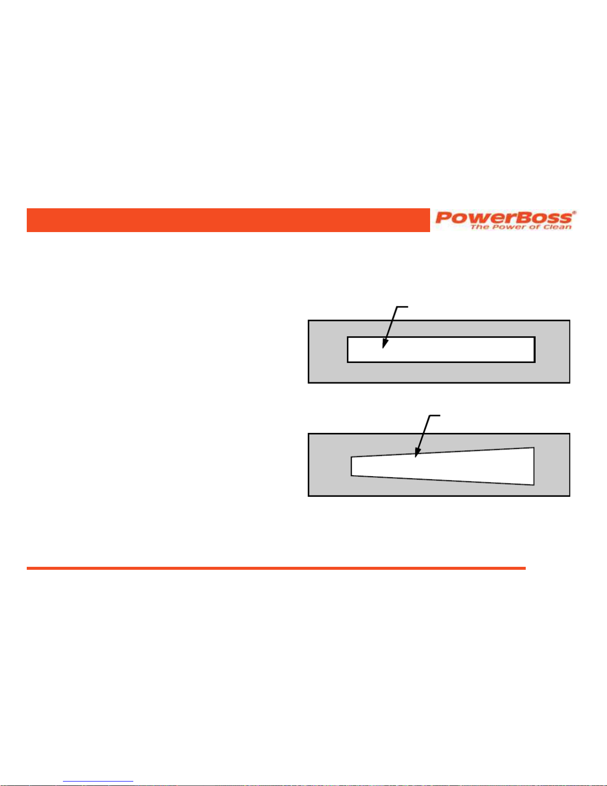
Commander T Series PB# 4100032 Rev.C 03/12
PowerBoss, Inc. Copyright 2011
Page 67
Main Broom Taper Adjustment
NOTE: It is not usually necessary to perform this
adjustment. However, if the main broom
adjustment test shows a pattern that is
tapered in length (one end is wider than
the other), perform the procedures which
follow.
1. Locate the hex-shaped adjustment bar on the left
rear wall of the broom chamber underneath the
machine.
2. Loosen the retaining bolt on the right side of the hex
bar.
3. Grasp the hex bar with a wrench and rotate it
to raise or lower the left end of the main broom.
(The right end of the broom remains xed. All
adjustments affect the left end of the broom.)
4. After adjustment, re-tighten the bolt.
5. Repeat the main broom adjustment test to see that
the broom is properly adjusted.
PREVENTATIVE MAINTENANCE
Correct Taper Pattern
Incorrect Taper Pattern
Page 68

PowerBoss, Inc. Copyright 2011
Commander T Series PB# 4100032 Rev.C 03/12
Page 68
Main Broom Replacement
NOTE: Broom should be replaced if bristles worn
to a length of 1 inch; 2.54 cm or less.
1. Turn the engine off and lock the parking brake.
2. Push the broom switch to the off position.
3. Open the left broom chamber door (the door
opposite the driver’s seat).
4. Remove the knob on the main broom idler mount.
5. Pull the main broom idler mount straight out to
remove.
6. Grasp the main broom by the plastic drive hub, pull
the main broom straight out and clear of the broom
chamber.
7. Depending on broom condition, you can either
rotate the old broom end-to-end and re-install it or
you can install a new broom. Slide the main broom
into the broom chamber and align the broom with
the metal drive hub located at the far side of the
broom chamber. If a worn broom is being replaced,
install the new broom by rst adjusting the broom
arms up to better match the position of the drive hub
with the hub on the new broom.
8. Once the broom is started onto the drive hubs,
rotate the broom counterclockwise while pushing
lightly against the broom.
9. Once the broom is fully engaged, replace the idler
hub while aligning the seats in the idler hub with the
broom’s drive hub ears.
10. Install the retaining knob and tighten into position.
11. Perform a main broom adjustment test and adjust
as needed.
PREVENTATIVE MAINTENANCE
Page 69
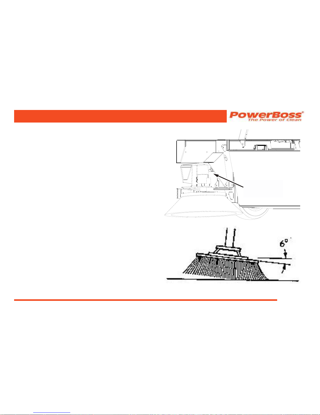
Commander T Series PB# 4100032 Rev.C 03/12
PowerBoss, Inc. Copyright 2011
Page 69
Side Broom Angle Adjustment
The angle adjustment is controlled with a bolt located on the
inside of side broom arm assembly.
1. Loosen the lock nut.
2. Turn the adjusting bolt until the broom is at the
optimum angle is 6 degrees.
3. Tighten the lock nut.
PREVENTATIVE MAINTENANCE
ANGLE
ADJUSTMENT
BOLT
Page 70
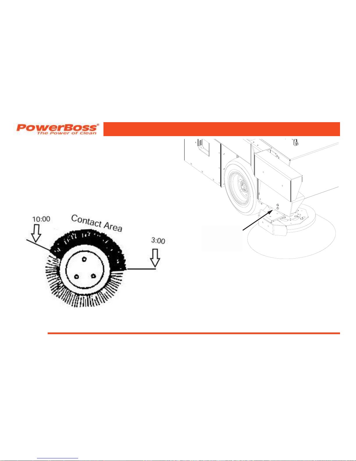
PowerBoss, Inc. Copyright 2011
Commander T Series PB# 4100032 Rev.C 03/12
Page 70
Side Broom Height (Wear) Adjustment
1. Stop the engine and lock the parking brake.
2. Position the side broom handle in LOWER position.
3. Loosen the side broom adjusting nuts located on the
exterior of the side broom arm assembly.
4. Adjust the side broom height be sliding the broom
assembly up or down until proper oor contact is
made in the “10 to 3 o’clock” position.
5. After adjustment, tighten the adjusting nut.
PREVENTATIVE MAINTENANCE
SIDE BROOM
HEIGHT
ADJUSMENT
NUTS
Page 71

Commander T Series PB# 4100032 Rev.C 03/12
PowerBoss, Inc. Copyright 2011
Page 71
Side Broom Lift Cable Adjustment
This adjustment is made at the cable clevis attached to
the side broom assembly. It controls the height of the side
broom in the RAISED position. This adjustment must be
made with the hopper fully lowered.
1. Pull the side broom lever into the RAISED position.
2. Loosen the locknut on the threaded rod at the
clevis.
3. Turn the threaded rod in or out to set the side broom
in the maximum raised position.
4. Secure the cable adjustment by tightening the
locknut.
PREVENTATIVE MAINTENANCE
Side Broom Replacement
NOTE: Broom should be replaced if bristles worn
to a length of 3 inches; 7.62 cm or less.
NOTE: The side broom features a quick release
mechanism which enables the operator to
remove the brush in seconds.
1. Raise the side broom and lock in the RAISE
position.
2. Turn the side broom by hand until the brush retainer
bar is accessible.
3. Lift the bar and turn the broom clockwise (about
one eighth of a turn) until the lock pins in the broom
disengage from the drive plate.
4. Install the new broom by positioning the three drive
pins into the pilot holes of the drive plate.
5. Lift and rotate the broom until the broom retainer bar
springs into the locked position.
6. Check to make sure all thee drive pins are properly
engaged.
Page 72

PowerBoss, Inc. Copyright 2011
Commander T Series PB# 4100032 Rev.C 03/12
Page 72
SCRUB & WATER PICK-UP COMPONENTS
WARNING
Never attempt to perform any service on the
equipment or components until the machine
is OFF, the parking brake is LOCKED and the
wheels are CHOCKED.
Scrub Brush Replacement
The Power-Dive scrub brush features a quick release
mechanism which enables the operator to remove the brush
in seconds.
NOTE: Brushes should be replaced when the
bristles are less than ½” (12.77 mm) long.
1. Raise the scrubhead.
2. Turn the scrub brush by hand until the brush locking
spring is accessible.
3. Squeeze the ends of the locking spring using a
downward motion and the brush will release from
the driver.
4. Install the new brush by positioning the socket in the
brush with the driver the on the scrub motor
5. Lift the brush until the brush retainer springs over
the driver locking it into position
6. Check to make sure that the brush is properly
engaged.
Scrubhead Gauge Adjustment
1. Raise the scrubhead to the full UP position.
2. Locate the linkage attached to the frame above the
scrubhead.
3. Loosen the set screw (the bolt running through the
arm).
4. Turn the potentiometer shaft until the gauge needle
points to the white dot at the left of the gauge.
5. Re-tighten the set screw. DO NOT OVER TIGHTEN!
NOTE: A gauge that is nonfunctional does not indicate
that the scrubhead is nonfunctional. The
scrubhead will continue to operate.
PREVENTATIVE MAINTENANCE
Page 73
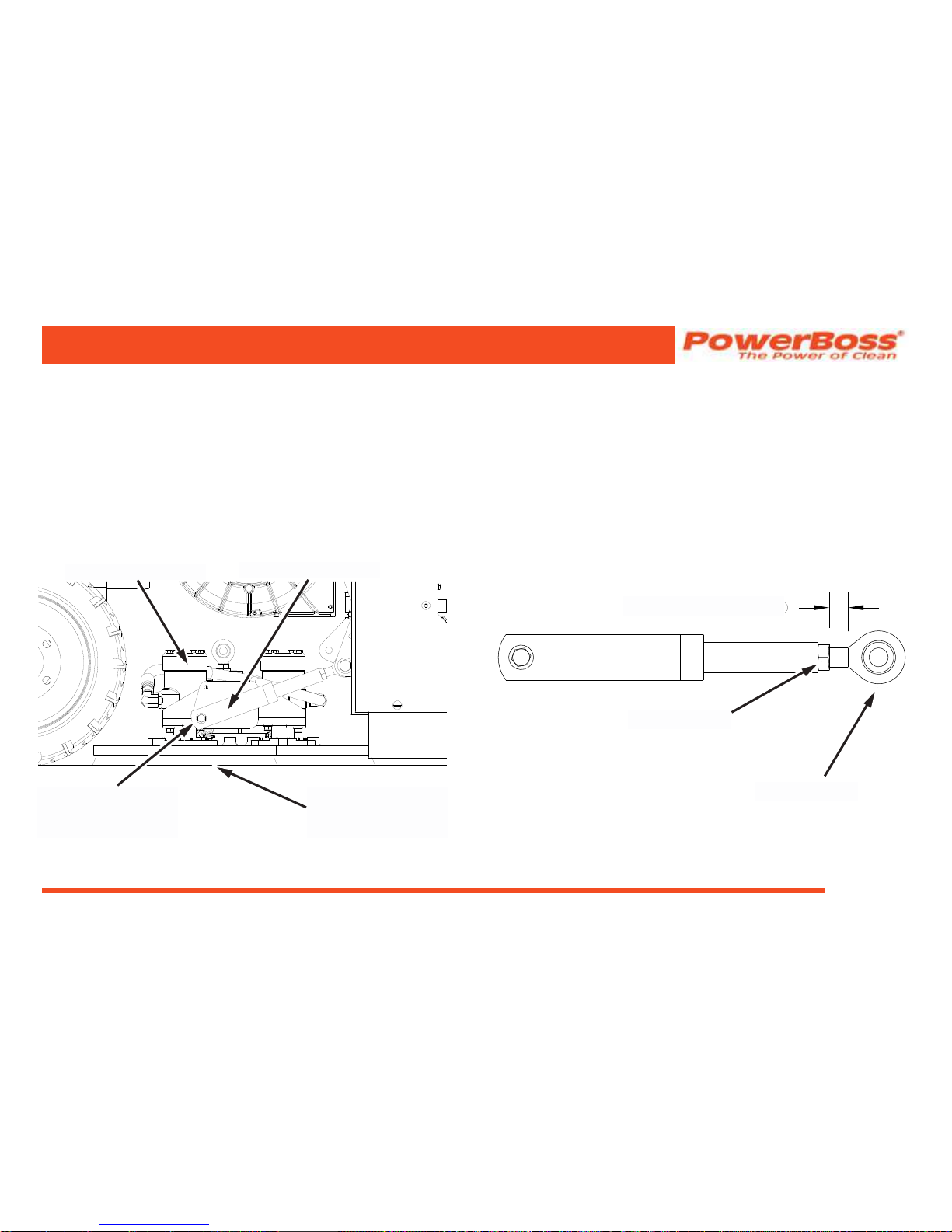
Commander T Series PB# 4100032 Rev.C 03/12
PowerBoss, Inc. Copyright 2011
Page 73
Scrubhead Adjustment
1. Park unit on a level oor and lower the scrubhead to
the full down position.
2. Open both scrub doors and remove the two hitch
pins from the right and left side squeegee blade.
Remove the right and left side squeegee blades.
3. Remove the bolts, washers and lock nuts holding
both lift arms to the scrub deck.
PREVENTATIVE MAINTENANCE
4. Loosen the jam nut securing the rod end to the lift
arms.
5. Adjust the rod end so that 1/2” (10 threads) of the
rod end extends from the lock nut on the lift arms.
NOTE: The 1/2”(10 threads) is a reference point to
start from.
LOWER SCRUB
DECK UNTIL FLAT
ON THE FLOOR
SCREW HOLDING
LIFT ARM TO
SCRUB DECK
SCRUB DECK
LIFT ARM
LOCK NUT
ROD END
1/2” (10 THREADS)
Page 74
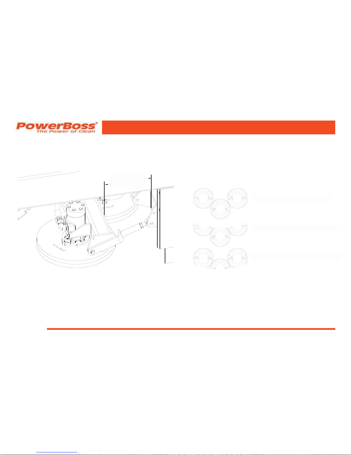
PowerBoss, Inc. Copyright 2011
Commander T Series PB# 4100032 Rev.C 03/12
Page 74
6. Measure from the from to the scrub deck, it should
be 8 1/2”(ref) for an 82 models or 9 1/4”(ref) for a 90
models. Make sure the measurement is the same
on both sides.
7. Align the holes in the lift arms with the hole in the
scrub deck on both sides. Adjust by rotating the lift
arm to move in or out on the rod end.
8. Attach the lift arm to the scrub deck on both sides
using the screws, washers and lock nuts.
9. Tighten the lock nut securing the rod ends to the lift
arms, both sides.
10. Close scrub doors and turn scrub deck on, shut
scrub deck off and raise the scrub deck.
11. Move the unit far enough to look at pattern created
on the oor, it should have three uniform circles.
12. If not readjust scrub deck. If pattern is ok, open
scrub doors and reinstall squeegee blades and hitch
pins on both sides.
13. Close scrub doors.
PREVENTATIVE MAINTENANCE
8 1/2”(REF)
OR
9 1/4”(REF)
CORRECT BRUSH PATTERN
INCORRECT BRUSH PATTERN
INCORRECT BRUSH PATTERN
Page 75

Commander T Series PB# 4100032 Rev.C 03/12
PowerBoss, Inc. Copyright 2011
Page 75
MAIN SQUEEGEE COMPONENTS
CHECKING and Adjusting the Rear Main Squeegee
Flare
NOTE: Perform check # 16 before proceeding to
make adjustments
1. Park the machine on a at surface. Lower the
squeegee.
2. Turn the machine off and engage the parking brake.
3. Open the access doors to the disc scrub brushes.
4. Locate & remove the pull pins for the side
squeegees, remove the side squeegees.
5. Lower the squeegee assembly
6. Release the quick-disconnect at the back of the rear
squeegee.
7. Loosen the locking nut on the squeegee caster and
screw the caster up until it clears the oor. With
the squeegee straight up on the oor (no are),
adjust the caster until it clears the oor by ½” (12.7
mm). Use a ½” (12.7 mm) shim spacer of metal or
wood as a feeler gauge for this procedure. This is a
starting reference.
PREVENTATIVE MAINTENANCE
8. Locate the squeegee lift arms on each side of the
machine.
9. Loosen the bolt which attaches the upper squeegee
lift arm to the squeegee mounting plate on each
side.
10. Locate and loosen both jam nuts on each squeegee
tilt adjustment link and back them away from the
gussets. The rear squeegee is now free to be
aligned with the oor. Lift the squeegee tool by hand
and allow it to rest back on the oor, this will seat
the tool to the oor. Again it should stand straight on
the oor with no are.
11. Check the squeegee rubber to make sure the
squeegee makes contact with the oor all the way
around.
12. At each squeegee arm mount, turn the two jam nuts
on the tilt adjusting link until they both make contact
with the mounting plate on each side.
13. Tighten the jam nuts on each mount plate. Then
tighten the bolt on top of each of the two upper
squeegee arms.
14. Tighten the nut on the caster.
Page 76

PowerBoss, Inc. Copyright 2011
Commander T Series PB# 4100032 Rev.C 03/12
Page 76
15. Reattach the squeegee lift linkage.
16. With the squeegee in the down position and
the Impeller on, drive the machine forward
approximately two feet (.61 meters) and set foot
brake. Examine the are in the squeegee rubber to
see that it is uniform around the entire parabola. If
not, go through Steps 4-17
17. Test unit for water pick up
NOTE: Raising the squeegee caster allows for more
are, use the tilt adjustments to even the are.
Turning or Replacing the Rear Squeegee Blade
The rear blade on the main squeegee frame has four
different edges that may be used: the front and back lower
edge and the front and back upper edge. When the edge
in use becomes worn to the midpoint of thickness, turn the
rubber to an unused edge in the order indicated:
1. Front Lower Edge,
2. Opposite Lower Edge,
3. Front upper Edge and
4. Opposite Upper Edge.
Removal and replacement instructions follow. This
procedure can be performed with the squeegee tool on or
off the machine.
NOTE: Removal and replacement of the inner squeegee
rubber is easier if the squeegee frame is
removed from the machine.
1. Unlatch the clamping strap at the center of the
squeegee frame and remove the 2 outer knobs.
2. Remove the metal strap, the two back-up strips and
the outer squeegee blade.
3. Turn the side ends of the squeegee blade 180°, or
turn the rubber upside down to expose an unused
edge. Reposition the blade on the pins of the
squeegee frame.
4. Reposition the rst back-up strip using the top
holes.
5. Reposition the second back-up strip using the
bottom holes.
6. Reposition the metal strap and reattach the two
outer knobs.
7. Reattach the straps at the center being careful not
to bunch the blade.
NOTE: Replace the back-up strips only if they
lose their elasticity.
PREVENTATIVE MAINTENANCE
Page 77

Commander T Series PB# 4100032 Rev.C 03/12
PowerBoss, Inc. Copyright 2011
Page 77
Main Squeegee Tool Removal
All machines are equipped with auto-squeegee lift. To
remove the squeegee tool, proceed as follows:
1. Engage the parking brake and chock the wheels.
2. Lower squeegee & pull the pin at the rear of the
squeegee tool.
3. Remove the knobs at the square lift arms supports.
4. Disconnect the vacuum hose from the squeegee.
5. Lift the supports up off the pins on the squeegee
frames and slide the squeegee away from the
machine.
Main Squeegee Tool Installation
1. At the back of the machine, push the squeegee
under the machine into position.
2. Attach the lift arms to the supports onto the pins on
the squeegee frame.
3. On each side of the squeegee, attach the hand
knobs (one on each side) to the squeegee frame
supports.
4. Connect the quick-release pin to the squeegee.
5. Connect the vacuum hose to the squeegee.
PREVENTATIVE MAINTENANCE
Inner Squeegee Replacement
The inner squeegee is a component of the rear squeegee
assembly. When the squeegee is down, locked and the rear
squeegee blade is ared, check to see if the inner squeegee
has become too worn to make proper even contact with the
oor.
1. Remove the main squeegee tool (see removal
instructions).
2. Remove the nuts on the front of the inner squeegee
frame.
3. Remove the strap and the inner squeegee rubber.
4. Install the new inner squeegee rubber.
5. Position the strap and secure with the nuts.
Auto Squeegee Lift Mechanism
Bearing Replacement: If any binding occurs in the lift
apparatus, replace the bushings, spacers and ber
glide bearings located on the squeegee lift assembly as
necessary.
NOTE: Bent components may cause binding.
Page 78
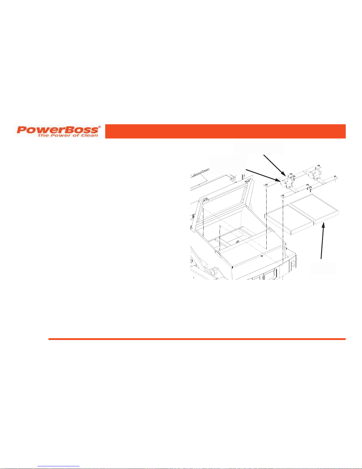
PowerBoss, Inc. Copyright 2011
Commander T Series PB# 4100032 Rev.C 03/12
Page 78
HOPPER
Hopper Filter Removal
1. Release the latches on the hopper hood and raise
the hood.
2. Disconnect the wire harnesses leading to the lter
shaker motors.
3. Remove the four bolts securing the each shaker
motor assembly to the hopper.
4. Remove the shaker motor assemblies.
5. Lift out the panel lters.
PREVENTATIVE MAINTENANCE
SHAKER
MOTOR
ASSEMBLY
MOTOR WIRE
HARNESS LEAD
PANEL
FILTER
Page 79

Commander T Series PB# 4100032 Rev.C 03/12
PowerBoss, Inc. Copyright 2011
Page 79
Hopper Filter Cleaning
The dust control lter is a polyester type element lter. It
may be vacuumed, blown out with compressed air, tapped
against the oor or washed with soap and water.
1. If blown out with compressed air, use 100 psi or
less.
2. If washed with soap and water, use 40 psi water
pressure or less.
NOTE: Make sure the lter is thoroughly dried
while standing on its side before installing
in the hopper. Do not install or use a
wet lter. Drying time is approximately
72 hours if air dried.
Hopper Filter Replacement
1. Insert the panel lter.
2. Install the shaker motor assembly.
3. Install and tighten the four lter retaining screws and
isolators.
4. Hook the wire harness to the lter shaker motors.
5. Close the hopper cover and secure the latch.
PREVENTATIVE MAINTENANCE
Page 80

PowerBoss, Inc. Copyright 2011
Commander T Series PB# 4100032 Rev.C 03/12
Page 80
Flap Replacement
Flaps located at the entrance lip of the hopper must be
replaced when worn or damaged. The ap panels may be
replaced separately.
1. Park the machine on a level surface and engage the
parking brake.
2. Raise the hopper.
3. Turn off the engine
4. Remove the ap retaining angle and worn or
damaged aps.
5. Install new aps.
6. Replace the retaining angle.
Frame Seal Replacement
Front Frame Seal
The hopper frame seal bolts to the front edge of the engine
pan. Install a new seal by folding it in half to align the holes.
Doubled edge with holes goes on the bottom. Support the
seal straight up while bolting the retainer bar in place. The
seal should fall over the retainer bar after installation. Be
certain that the seal edges are aligned to prevent twisting of
the seal.
Side Frame Seal
The side frame seals should clear the oor by at least ⅛”
(3.18 cm). If the bottom of a side seal measures ½” (1.27
cm) or more above the oor, readjust it or replace it by
removing the bolts on the inside of the wheel wells, installing
a new seal, and securing it with the bolts. The double edge
with the holes goes toward the front.
PREVENTATIVE MAINTENANCE
Page 81
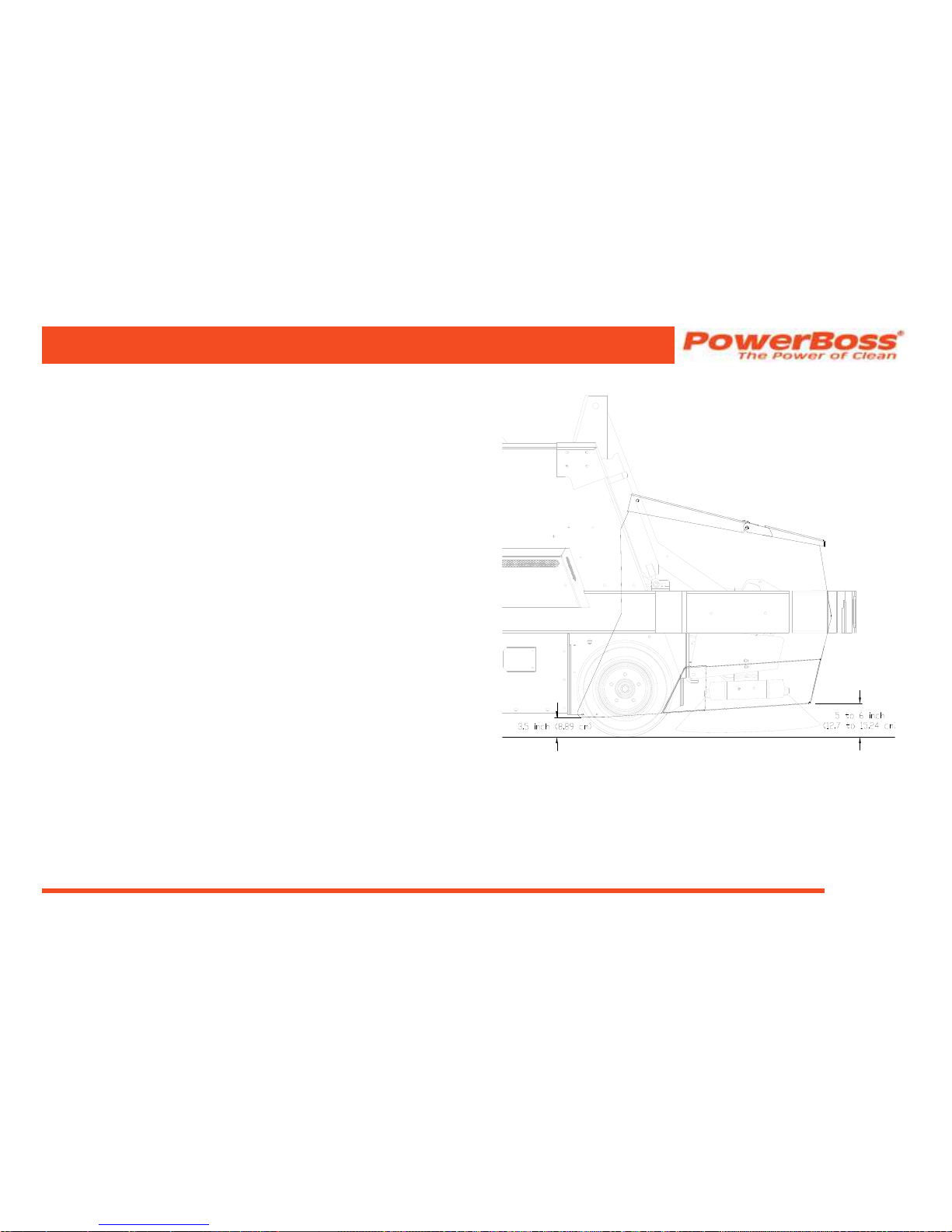
Commander T Series PB# 4100032 Rev.C 03/12
PowerBoss, Inc. Copyright 2011
Page 81
Floor Clearance
In order to perform properly, the hopper must maintain a
distance of 3½” (8.89 cm) from the oor to the rear hopper
entrance lip. The front of the hopper should be adjusted so
that the front bumper aligns with the hopper frame where
the two meet. When properly adjusted, the front edge of the
hopper will be 5” (12.7 cm) to 6” (15.24 cm) from the oor.
Refer to service manual for adjusting oor clearance.
PREVENTATIVE MAINTENANCE
Page 82

PowerBoss, Inc. Copyright 2011
Commander T Series PB# 4100032 Rev.C 03/12
Page 82
Vacuum Gasket Mount Adjustment
1. With the hopper in the normal position, observe
contact between the back of the hopper and gasket.
If complete seal is not maintained, raise the high
dump hopper.
WARNING
Do not rely upon the hydraulic cylinders to keep
the hopper raised for maintenance. Always
engage the safety arm before servicing the
hopper.
2. Loosen the mounting bolts in the gasket mount.
Move the assembly toward the hopper. Tighten the
bolts. Test and repeat if necessary.
PARKING BRAKE
Normal adjustment of the parking brake can be
accomplished from the operator compartment. Locate the
knurled handle on the parking brake lever. Turn the handle
clockwise to increase brake tension.
NOTE: Two or three turns is usually adequate. DO
NOT OVERTIGHTEN.
If this adjustment becomes ineffective, it will be necessary to
adjust the cable length.
PREVENTATIVE MAINTENANCE
Page 83

Commander T Series PB# 4100032 Rev.C 03/12
PowerBoss, Inc. Copyright 2011
Page 83
Adjusting The Parking Brake Cable Length
1. Park the machine on a level surface and chock the
wheels.
2. Place the parking brake lever in the OFF position.
3. Turn the knurled handle counter-clockwise to loosen
the tension as far as possible.
4. Locate the cable clevis ends for the parking brake
cables in the left front wheel well.
5. Disconnect the clevis ends from the bar.
6. Loosen the jam nuts at the base of the clevis.
7. Turn the clevis clockwise three or four complete
turns.
8. Tighten the jam nuts and re-install the clevis ends
onto the bar.
9. Adjust the knurled handle on the parking brake
lever.
Cable Adjustment for Standard brake
1. Locate the parking brake cable in the top of the left
wheel well opening.
2. Loosen the locking nut located against the hex bar.
3. Thread the cable end into the hex bar.
4. If threads are not sufcient for adjustment,
disconnect the springs, move the cable bars to the
next adjusting hole on the hex bar and reconnect
the springs.
5. Retighten the locking nut against the hex bar. This
adjusts both sets of brake shoes.
6. Test the brakes. Readjust if necessary.
PREVENTATIVE MAINTENANCE
Page 84

PowerBoss, Inc. Copyright 2011
Commander T Series PB# 4100032 Rev.C 03/12
Page 84
CHANGING SOLID TIRES
NOTE: The procedures which follow apply to
SOLID TIRES ONLY.
Front Tire
1. Remove the tire from the vehicle by removing the
ve inner lug nuts.
2. Remove the ten hex head bolts and nuts.
3. Press the tire from the rim.
4. Press the large rim half into the new tire.
5. Mount the small rim half and secure with hex head
bolts.
6. Reinstall the tire on the machine
Rear Tire
The rear tire is a special traction rubber compound press-on
type tire.
MISCELLANEOUS ADJUSTMENTS
Anti-Static Chain Adjustment
Each machine is equipped with an anti-static chain bolted
to the back wall of the broom chamber. This should remain
in contact with the oor at all times. Inspect the chain every
200 operating hours. Replace if at least one link does not
drag the surface of the oor.
Latch and Hinge Maintenance
Latches and hinges should be inspected after every 500
hours of use. Retighten and oil if necessary.
Cables
Inspect all cables for wear every 500 hours.
PREVENTATIVE MAINTENANCE
Page 85

Commander T Series PB# 4100032 Rev.C 03/12
PowerBoss, Inc. Copyright 2011
Page 85
TROUBLESHOOTING
This section provides information to assist in identifying maintenance trouble and provides possible causes and actions to
Service must be preformed by an approved authorized repair station.
TROUBLESHOOTING CHART
PROBLEM POSSIBLE CAUSE(S) SOLUTION(S)
Engine will not start or runs
roughly after start.
NOTE: On machines with LP
fuel, also check the following:
Battery dead. Recharge or replace battery.
Machine out of fuel. Refuel
Fuel lter plugged. Clean or replace lter.
Fuel line broken or obstructed. Blow fuel line out with compressed air.
Dirty air lter. Clean or replace air lter.
Problems with spark plugs, ignition points,
ignition coil ignition switch, carburetor,
regulator, wiring harness.
Review engine manual at back of
this manual for maintenance and
troubleshooting procedures.
Tank valve not fully opened. Open the valve slowly.
Fuel tank type does not match fuel supply. Use the correct tank type for the fuel
supply.
Fuel tank and lines are covered with frost. Open shut-off valve slowly to ¼ open,
start.
Defective vacuum lock-off. Replace or repair.
TROUBLESHOOTING
Page 86

PowerBoss, Inc. Copyright 2011
Commander T Series PB# 4100032 Rev.C 03/12
Page 86
TROUBLESHOOTING CHART
PROBLEM POSSIBLE CAUSE(S) SOLUTION(S)
Engine overheats.
NOTE: If coolant loss has not
occurred, check for malfunction
of the temperature sending unit.
Low coolant level. Supply coolant.
Fan blade installed incorrect Reinstall (pusher type fan)
Clogged radiator. Flush radiator.
Loose fan belt. Tighten belt.
Defective thermostat. Replace thermostat.
PowerBoss® moves slowly
or does not move.
Parking brake is on. Release brake.
Directional control pedal jammed, damaged, or
not adjusted properly.
Clear jam or adjust linkage.
Tow valve in tow position Move to drive position
Low hydraulic uid level. Add hydraulic uid.
Hydraulic uid temperature too high and too
thin caused by excessive load, climbing, high
environment temperatures, worn pump, or
improper uid.
Use the proper weight oil for the
operation conditions; check pump.
Hayes coupler failed Replace
Other problems with the hydraulics system:
pump failure, motor failure, relief valve leaking
or stuck open.
See Hydraulics System
Problems in this section.
Tow Valve improperly set. Turn to correct position.
TROUBLESHOOTING
Page 87

Commander T Series PB# 4100032 Rev.C 03/12
PowerBoss, Inc. Copyright 2011
Page 87
TROUBLESHOOTING CHART
PROBLEM POSSIBLE CAUSE(S) SOLUTION(S)
PowerBoss® creeps in neutral. Directional control pedal return spring is out of
adjustment.
Perform the adjustment procedures.
Brushes do not turn or turn very
slowly.
Hydraulic system problem: See Hydraulics System Problems in this
section.
Motor
Control valve
Gear pump
Relief valve
Brush switch not on Press to on position
Foot pedal not depressed Press to forward position
Little or no vacuum in brush
compartment.
Filters clogged. Clean lters.
Leak or clog in hose from impeller. Repair leaks; clear obstructions or
replace hose.
Impeller failure. Check and repair.
Scrubhead will not lower. Fuse blown. Replace fuse.
Loose scrubhead switch wires. Connect wires.
Loose connection of plug at actuator. Connect.
Defective actuator. Replace actuator.
Defective scrubhead switch. Replace switch.
TROUBLESHOOTING
Page 88

PowerBoss, Inc. Copyright 2011
Commander T Series PB# 4100032 Rev.C 03/12
Page 88
TROUBLESHOOTING CHART
PROBLEM POSSIBLE CAUSE(S) SOLUTION(S)
Poor water pick-up Recovery tank is full. Empty the tank; if foaming badly, change
detergent.
Squeegee worn. Replace squeegee.
Debris caught in squeegee or pick-up tube. Remove debris.
Leak or clog in hose from impeller. Repair leak, clear obstruction or replace
hose.
Squeegee out of adjustment. Adjust squeegee.
Engine not operating at high speed. Check Throttle Switch Position
Impeller failure. Check and repair.
Solution not being delivered. Solution tank is empty. Fill tank.
Solution pump not on. Check Switch
Solution ow valve not functioning Check broom switch & pressure
switches @ main pump
Delivery lines clogged. Clear lines.
Fwd/Rev Pedal not depressed Press pedal
Solution valve out of lever adjustment. Adjust.
TROUBLESHOOTING
Page 89

Commander T Series PB# 4100032 Rev.C 03/12
PowerBoss, Inc. Copyright 2011
Page 89
TROUBLESHOOTING
TROUBLESHOOTING CHART
PROBLEM POSSIBLE CAUSE(S) SOLUTION(S)
Scrubber unit not cleaning the
oor.
Brushes worn. Replace.
Need different type of brush or detergent. Use manufacturer’s recommended
brushes / detergent.
Debris caught in brush drive mechanism. Clear obstruction.
Brushes out of adjustment. Adjust.
Brush motor failure. See Hydraulics System Problems.
Squeegee will not lower. Loose or defective squeegee switch (on
console).
Reconnect wiring or replace switch.
Loose wire(s) at foot pedal. Connect.
Foot pedal switches need adjustment. Re-adjust cams.
Squeegee will not raise in
reverse or by console switch.
Foot pedal switches need adjustment. Re-adjust cams.
Defective waterman valve Check coil @ valve
Lift springs worn out or missing. Replace springs.
Bad ground at valve. Check ground.
No power at valve. Check fuse
NOTE: Power At The Waterman Valve = Squeegee In The Up Position
No Power At Valve = Squeegee In Down Position
Page 90

PowerBoss, Inc. Copyright 2011
Commander T Series PB# 4100032 Rev.C 03/12
Page 90
TROUBLESHOOTING CHART
PROBLEM POSSIBLE CAUSE(S) SOLUTION(S)
Loss of dust control. Debris in hose or impeller inlet. Clean.
Broom skirts or seal worn. Replace.
Skirt clearance from oor exceeds ⅛”. Adjust clearance.
Dust control lters clogged. Clean lters.
Filter seals worn or missing. Replace.
Poor seal with vacuum gasket. Visually check and adjust, if necessary.
Sweeper unit leaving debris. Hopper full. Dump hopper.
Broom(s) out of adjustment. Adjust.
Broom bristles worn. Check broom for wear and adjustment.
Poor performance of broom drive mechanism. Check for jam in broom chamber.
Broom lift arms hung up with debris. Clear out debris.
Hopper aps damaged or missing. Replace or adjust clearance.
Hopper out of adjustment. Check hopper clearance.
Dust control lters clogged. Clean lters.
Hopper lift cylinder failure. Line to cylinder leaking. Tighten ttings or replace hose.
Piston seals leaking. Replace seals.
Bent piston rod. Replace rod.
TROUBLESHOOTING
Page 91

Commander T Series PB# 4100032 Rev.C 03/12
PowerBoss, Inc. Copyright 2011
Page 91
TROUBLESHOOTING CHART
PROBLEM POSSIBLE CAUSE(S) SOLUTION(S)
Hopper does not raise or lower. Hydraulics system problem: See Hydraulics Systems
Problems in this section.
Control valve
Gear pump
Lift cylinder
Relief valve
Hopper arms binding. Lubricate or adjust arm linkage.
Hopper does not rotate or rotates
too slowly.
Hopper load too heavy. Dump more frequently.
Hydraulics system problem: See Hydraulics System
Problems in this section.
Control valve
Gear pump
Lift cylinder
Relief valve
Hydraulic control valve failure Misaligned control linkage. Align.
Foreign matter in spool bore. Remove spool and clean bore.
Valve seals Leaking. Replace seals.
O-rings leaking. Replace O-rings
Relief valve stuck open. Clean or replace relief valve.
TROUBLESHOOTING
Page 92

PowerBoss, Inc. Copyright 2011
Commander T Series PB# 4100032 Rev.C 03/12
Page 92
TROUBLESHOOTING CHART
PROBLEM POSSIBLE CAUSE(S) SOLUTION(S)
Hydraulic drive motor failure. Insufcient oil supply Fill Reservoir
Motor leaking. Replace seals.
Drive pump coupler failed Replace
Key on motor shaft failed Replace key
Drive hub failed Replace
Output shaft malfunction. Replace output shaft and bearings.
Hydraulic gear pump failure. Pump leaking. Replace seals or RR Pump
Drive coupler failed Replace
Gears worn or scored. Rebuild pump or RR Pump
Relief valve stuck. Clean or replace (at control valve).
Oil supply low. Check and ll.
Oil strainer clogged. Replace strainer (inside reservoir).
Incorrect oil. Use recommended viscosity oil.
Damage due to entry of air into hydraulic
system.
Maintain correct hydraulic uid level
in reservoir. Keep suction hose ttings
tight..
TROUBLESHOOTING
Page 93

Commander T Series PB# 4100032 Rev.C 03/12
PowerBoss, Inc. Copyright 2011
Page 93
TROUBLESHOOTING CHART
PROBLEM POSSIBLE CAUSE(S) SOLUTION(S)
Hydraulic variable displacement
pump failure.
Pump leaking. Replace seals.
Relief valve(s) stuck. Clean or replace relief valve(s) at the
pump.
Drive coupling malfunction. Replace defective gears.
Control linkage out of adjustment. Check to see if linkage is binding
unfastened.
Charge pump gears worn or scored. Replace defective gears.
Damage due to entry of air into hydraulic
system.
Maintain correct hydraulic uid level
in reservoir. Keep suction hose ttings
tight.
Hydraulic system noisy. Air in system. Check uid level in reservoir; check for
loose connections or leaks.
Relief valve dirty or damaged. Clean or replace.
Loose suction line. Tighten ttings.
Clogged section lter or pump inlet line. Replace lter, clear line; change uid in
reservoir if dirty and ush system.
Internal pump or motor damage. Inspect and repair.
TROUBLESHOOTING
Page 94

PowerBoss, Inc. Copyright 2011
Commander T Series PB# 4100032 Rev.C 03/12
Page 94
Revision G
Effective September 2010
PowerBoss Made Simple Industrial Limited Warranty
Minuteman International owner of PowerBoss warrants to the original purchaser/user that the product is free from defects in workmanship and materials under
normal use. PowerBoss will, at its option, repair or replace without charge, parts that fail under normal use and service when operated and maintained in
accordance with the applicable operation and instruction manuals. All warranty claims must be submitted through and approved by factory authorized repair
stations.
This warranty does not apply to normal wear, or to items whose life is dependent on their use and care. Parts not manufactured by PowerBoss are covered by and subject to the
warranties and/or guarantees of their manufacturers. Please contact Minuteman International for procedures in warranty claims against these manufacturers.
Special warning to purchaser -- Use of replacement parts not manufactured by PowerBoss or its designated licensees, will void all warranties expressed or
implied. A potential health hazard exits without original equipment replacement.
All warranted items become the sole property of Minuteman International or PowerBoss or its original manufacturer, whichever the case may be.
PowerBoss disclaims any implied warranty, including the warranty of merchantability and the warranty of fitness for a particular purpose. PowerBoss assumes no
responsibility for any special, incidental or consequential damages.
This limited warranty is applicable only in the U.S.A. and Canada, and is extended only to the original user/purchaser of this product. Customers outside the U.S.A.
and Canada should contact their local distributor for export warranty policies. PowerBoss is not responsible for costs or repairs performed by persons other than
those specifically authorized by PowerBoss. This warranty does not apply to damage from transportation, alterations by unauthorized persons, misuse or abuse of
the equipment, use of non-compatible chemicals, or damage to property, or loss of income due to malfunctions of the product. If a difficulty develops with this
machine, you should contact the dealer from whom it was purchased.
This warranty gives you specific legal rights, and you may have other rights, which vary from state to state. Some states do not allow the exclusion or limitation of
special, incidental or consequential damages, or limitations on how long an implied warranty lasts, so the above exclusions and limitations may not apply to you
.
WARRANTY
Page 95

Commander T Series PB# 4100032 Rev.C 03/12
PowerBoss, Inc. Copyright 2011
Page 95
Revision G
Effective September 2010
PowerBoss Made Simple Industrial Limited Warranty
Minuteman International owner of PowerBoss warrants to the original purchaser/user that the product is free from defects in workmanship and materials under
normal use. PowerBoss will, at its option, repair or replace without charge, parts that fail under normal use and service when operated and maintained in
accordance with the applicable operation and instruction manuals. All warranty claims must be submitted through and approved by factory authorized repair
stations.
This warranty does not apply to normal wear, or to items whose life is dependent on their use and care. Parts not manufactured by PowerBoss are covered by and subject to the
warranties and/or guarantees of their manufacturers. Please contact Minuteman International for procedures in warranty claims against these manufacturers.
Special warning to purchaser -- Use of replacement parts not manufactured by PowerBoss or its designated licensees, will void all warranties expressed or
implied. A potential health hazard exits without original equipment replacement.
All warranted items become the sole property of Minuteman International or PowerBoss or its original manufacturer, whichever the case may be.
PowerBoss disclaims any implied warranty, including the warranty of merchantability and the warranty of fitness for a particular purpose. PowerBoss assumes no
responsibility for any special, incidental or consequential damages.
This limited warranty is applicable only in the U.S.A. and Canada, and is extended only to the original user/purchaser of this product. Customers outside the U.S.A.
and Canada should contact their local distributor for export warranty policies. PowerBoss is not responsible for costs or repairs performed by persons other than
those specifically authorized by PowerBoss. This warranty does not apply to damage from transportation, alterations by unauthorized persons, misuse or abuse of
the equipment, use of non-compatible chemicals, or damage to property, or loss of income due to malfunctions of the product. If a difficulty develops with this
machine, you should contact the dealer from whom it was purchased.
This warranty gives you specific legal rights, and you may have other rights, which vary from state to state. Some states do not allow the exclusion or limitation of
special, incidental or consequential damages, or limitations on how long an implied warranty lasts, so the above exclusions and limitations may not apply to you
.
Travel* Labor Parts Engine Extended Warranty Costs
Walk behinds
Battery sweepers Ninety days One year One year N/A 2 years Parts + Labor (or 2000 Hours
2%
IC sweepers Ninety days One year One year Through manufacturer 2 years Parts + Labor (or 2000 Hours
2%
Battery scrubbers Ninety days Two years Three years N/A 3 Years Parts + Labor (or 3000 Hours)
2%
Riders
Battery scrubbers Ninety days Two years Three years/2000 hrs N/A 3 Years Parts + Labor (or 3000 Hours)
2%
IC sweeper/scrubbers Ninety days Six months Two years/2000 hrs Two years/3000 hrs** 2 years Parts + Labor (or 2000 Hours
3%
IC sweepers Ninety days Six months Four years/3000 hrs Five years/3000 hrs**
Exceptions
Apex series sweeper Ninety days One year One year/1000 hrs One year/1000 hrs** 2 years Parts + Labor (or 2000 Hours)
3%
6X sweeper Ninety days Six months Two years/2000 hrs Two years/2000 hours** 2 years Parts + Labor (or 2000 Hours)
3%
Other Products
QRE-3001A Ninety days Six months Two years/2000 hrs Two years/3000 hours** 2 years Parts + Labor (or 2000 Hours)
3%
4 Years Parts + 2 Years Labor (or 4000
Hours)
3%
Tank Bladders Eight years/ no additional labor
Polyethylene plastic tanks Ten years/ no additional labor
Batteries 0-3 months full replacement, 4-12 prorated credit
Chargers One-year replacement
Replacement parts Ninety days
*Two-hour cap
**Through engine manufacturer. See section 3 of warranty manual for engine warranty exceptions
*** Based upon dealer’s certification status
Extended Warranty MUST be signed up within 30 days of delivery to End User (Dealer has 1Year from Receiving Machine to Sign up extended Warranty)
Extended Warranty Cost is based on Invoice Price multiplied by the Percentage listed in the Extended Warranty Column
All above labor and travel reimbursed at 65 or 75% of the published shop rate.
WARRANTY
Page 96

“The Power of Clean”
PowerBoss Is A Full Line Manufacturer Of Sweepers and Scrubbers For
Industrial Facilities.
 Loading...