

PowerBoss T82, C82, C90, T90 User Manual

PowerBoss,Inc.
A Member Of The Hako Group
PB # 4100032 / Rev. 01A08
OMMANDER SERIES
T
82 / T90
C
82 / C90
U
SERS MANUAL

PB # 3308731 / Rev. 00D02
PowerBoss,Inc.
A Member Of The Hako Group
PB # 4100032 / Rev. 01A08
OMMANDER SERIES
T
82 / T90
C
82 / C90
U
SERS MANUAL
User Manual
All information contained in this manual is current at the time of printing. However, due to constant
updates and improvements, we reserve the right to make changes at any time without notice.
© Copyright 2008, PowerBoss, Inc.
All rights reserved. This manual may not be copied or reproduced in any form, without the written
permission of Minuteman PowerBoss, Inc.
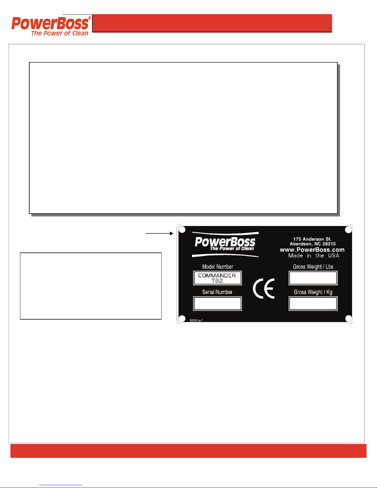
The Model and Serial Numbers of your machine are shown on the I.D. name plate. This I.D.
plate is mounted on the console of the machine below the throttle switch for LP & Gasoline
units and Below the Throttle cable for diesels units. This information is needed when
contacting Technical Support or when ordering parts. For your convenience, use the space
below to record the Model and Serial Numbers of your machine and the date it was placed
into service.
MODEL NUMBER: ___________________________________________
SERIAL NUMBER: ___________________________________________
DATE PLACED INTO SERVICE: _______________________________
E-mail; techsupport@powerboss.com
Phone Number; Customer Service 800-982-7141
I.D. Name Plate
How To Read PowerBoss Serial Number
I.E. SN = xxxxx108
XXXXX = Sequence Of Assigned Number
10 = Month (October)
8 = Year (2008)
PowerBoss® Commander Series Sweeper Scrubber
PB # 4100032 / Rev. 04A08
PowerBoss, Inc. Copyright 2008

COMMANDER SERIES
8
2 / 90
U
SERS MANUAL
O
PERATION, MAINTENANCE &
T
ROUBLESHOOTING
PB # 4100032 / Rev. 01A08
W a r ra n t y . .. . .. . . .. . .. . . .. . .. . .. . . .. . .. . . .. . .. . . .. . .. . .. . . .. . .. . . .. . .. . . 9 - 1 0
S A F E T Y
S af e t y S ym b o ls . .. . .. . .. . . .. . .. . . . . . .. . .. . . .. . .. . . .. . .. . .. . . .. . .. . . .. . .. . 1 1
S af e t y D e c a l s … . …… … … …… … … …… … … …… . . …… … .. 1 2 - 1 3
S af e t y .. . .. . .. . . .. . .. . .. . . .. . .. . . .. . .. . .. . . .. . .. . . .. . .. . .. . . .. . .. . . .. . .. 1 4 - 1 6
O P E R AT I O N
B as i c O p er a t i ng Co n t ro l s . . .. . .. . . .. . .. . . .. . .. . . .. . .. . . . . . .. . .. . . 1 7 - 2 3
O p e ra t i n g Pr o c e d u r e s
P re - O pe r a ti o n C h ec k . .. . . .. . .. . .. . . .. . .. . . . . . .. . .. . . .. . .. . . . . . .. . .. . . .. 2 4
S ta r t in g …… … . . . .. . .. . . .. . .. . .. . . .. . .. . . .. . .. . .. . . .. . .. . . .. . .. . . .. . .. . .. . 2 4
S lo w i ng an d St o p pi n g . .. . . . . . .. . .. . . .. . .. . . . . . .. . .. . . .. . .. . . .. . .. . . . . . 2 4
O pe r a ti n g o n G r a de s . .. . .. . . .. . .. . .. . . .. . .. . . .. . .. . .. . . .. . .. . . .. . .. . . .. 2 4
O p t io n a l B lo w e r . . .. . . .. . .. . . . . . .. . .. . . .. . .. . . .. . .. . .. . . .. . .. . . .. . .. . . . . 2 5
T r a ns p o r t i ng M a c hi n e . .. . .. . . .. . .. . . . . . .. . .. . . .. . .. . . .. . .. . .. . . .. . . 25
P us h i ng . .. . .. . . .. . .. . . .. . .. . .. . . .. . .. . . .. . .. . .. . . .. . .. . . .. . .. . . . . . .. . .. . 2 5
T A B L E O F C O N T E N T
T A B L E O F C O N T E N T
T A B L E O F C O N T E N T
S
S
S

USERS MANUAL
PAGE 5
PowerBoss, Inc. Copyright 2008
PowerBoss® Commander Series Sweeper Scrubber PB # 4100032 / Rev. 01A08
M A IN T E N A N C E
I nt r o du c t i o n . .. . .. . . .. . .. . . . . . .. . .. . . .. . .. . . .. . .. . .. . . .. . .. . . .. . .. . . .. . .. . . 2 6
P l a nn e d M a in t e n a nc e C h a r t
G M1 . 6 LE n g in e . .. . .. . . .. . .. . . .. . .. . .. . . .. . .. . . .. . .. . . . . . .. . 2 7
K ub o t a V 1 50 5 … … … …… … … …… … … …… … … … . 2 7
E ng i n e ( St a n da r d M a i nt e n an c e ) . .. . .. . .. . . .. . .. . . .. . 2 8
A ir I nt a k e S ys t e m . .. . . .. . .. . . . . . .. . .. . . .. . .. . . . . . .. . .. . . . 2 8
E le c t ri c a l S ys t e m . .. . .. . . .. . .. . . .. . .. . .. . . .. . .. . . .. . .. . . . 2 8
C oo l a nt S ys t e m .. .. . . .. . .. . . . . . .. . .. . . .. . .. . . . . . .. . .. . . .. . 2 8
H yd r a ul i cs S ys t e m .. . .. . . .. . .. . . .. . .. . . . . . .. . .. . . .. . .. . . . 2 9
H op p e r . . .. . .. . . . . . .. . .. . . .. . .. . . .. . .. . .. . . .. . .. . . .. . .. . . . . . .. 3 0
S te e r in g . . . .. . .. . . . . . .. . .. . . .. . .. . . .. . .. . .. . . .. . .. . . .. . .. . . .. 3 0
P ar k i ng B r a k e . .. . . .. . .. . .. . . .. . .. . . .. . .. . .. . . .. . .. . . .. . .. . 3 0
T an k s . . .. . .. . . .. . .. . . .. . .. . .. . . .. . .. . . .. . .. . .. . . .. . .. . . .. . .. . 3 0
T ir e s . .. . . .. . .. . . .. . .. . . . . . .. . .. . . .. . .. . . . . . .. . .. . . .. . .. . . .. . .. 3 1
M is c e ll a ne o u s . .. . .. . . .. . .. . . .. . .. . . .. . .. . .. . . .. . .. . . .. . .. . 3 1
I mp e l le r . . .. . . .. . .. . . .. . .. . .. . . .. . .. . . .. . .. . .. . . .. . .. . . .. . .. . 3 1
S cr u b a n d W a t er Pi c k -u p Co m p on e n ts . .. . .. . . . . . . 3 1
S e r vi c e I n s t r u c t i on s
I nt r o du c ti o n . . . .. . .. . . .. . .. . .. . . .. . .. . . .. . .. . .. . . .. . .. . . .. . . 3 2
A ir I nt a ke
A ir F il t er R em o v a l . .. . .. . . .. . .. . . .. . .. . . . . . .. . .. . . 3 3
A ir F il t e r C le a n in g . .. . .. . . .. . .. . .. . . .. . .. . . .. . .. . . 3 3
A ir F il t er I ns p e ct i o n. . . . . . .. . .. . . .. . .. . . .. . .. . .. . . 3 3
A ir F il t e r I ns t a l l a t io n . . .. . .. . . . . . .. . .. . . .. . .. . . .. 3 3
E le c t ri c al S ys t e m
B at t er y Cl e a ni n g . . . .. . .. . . .. . .. . . .. . .. . . . . . .. . .. . . 3 4
B at t e ry Re p l a ce m en t . .. . .. . . .. . .. . . . . . .. . .. . . .. . 3 4
C ir c u it B re a ke r / F u se s . . .. . . .. . .. . .. . . .. . .. . . .. 3 4
F ue l Sy s te m
W A RN I N G S . .. . . .. . .. . . .. . .. . . . . . .. . .. . . .. . .. . . .. . .. 3 5
C oo l a nt S ys t e m
B lo w i ng O ut R ad i at o r F i n s . . .. . .. . . .. . .. . . . . . .. 3 6
R ev e r se Fl o w F l u sh i n g .. . .. . . .. . .. . .. . . .. . .. . . .. 3 6
L ub r i ca t i o n
C ha n gi n g E n g in e Oi l . . . .. . .. . . .. . .. . . .. . .. . . .. . .. 3 7
L ub r i ca t io n Po i n ts . . .. . . .. . .. . .. . . .. . .. . . .. . . 3 7 - 3 8
TA B L E O F C O N T E N T S ( C o n t i n u e d )

USERS MANUAL
PAGE 6
PowerBoss, Inc. Copyright 2008
PowerBoss® Commander Series Sweeper Scrubber
PB # 4100032 / Rev. 01A08
M A IN T E N A N C E ( C O N T IN U E D )
S e r vi c e I n s t r u c t i on s ( C o nt i n u e d )
H yd r a ul i cs S ys t e m
F il l i ng th e H yd r au l i c F l ui d Re s er v o ir . .. . . .. 3 9
C ha n gi n g t h e H y d ra u l ic F lu i d . . .. . .. . .. . . .. . .. 3 9
C ha n gi n g t h e H y d ra u l ic F lu i d F i l te r . . . . . .. . 40
A dj u s ti n g t h e D i re c t io n a l C o nt r o l
R et u r n S pr i n g . . . .. . .. . . .. . .. . .. . . .. . .. . . .. . .. . .. . . . 4 0
S k i rt s & F la p s
B ro o m D o or F la p In s pe c t i on . . .. . .. . . .. . .. . .. . . 4 1
B ro o m D o or F la p Re p la c e m e n t
a nd A dj u st m e nt . . .. . .. . . .. . .. . .. . . .. . .. . . .. . .. . .. . . 4 1
M a i n B r o o m & A d j u st m e n t
M ai n Br o om P a tt e rn C he c k … … … …… . 4 1 -4 2
M a in B ro o m H e i gh t A d j us t m en t .. . . . . . .. . .. . . 4 2
M ai n Br o om T a p e r A d j us t m en t . .. . . .. . .. . .. . . 4 3
M ai n Br o om R ep l a ce m e nt . . . .. . .. . . .. . .. . .. . . .. 44
S i d e B r o o m ( O p t i o n al O n C8 2 & C 90 )
S i de B r o o m A n g le Ad j u st m e nt . . .. . .. . .. . . .. . . 4 5
S id e Br o om H e i g h t ( W e ar ) A d j us t me n t . . . . 4 5
S id e Br o o m L i f t Ca b l e A d ju s t m e n t . . . .. . .. . . 4 5
S id e Br o om R ep l a ce m e nt . . . . . .. . .. . . .. . .. . .. . . 4 6
S c r ub a n d Wa t e r P i c k - u p C om p o n e nt s
S cr u b B r us h R ep l ac e m en t .. . . .. . .. . . .. . .. . .. . . 4 7
S cr u b he a d G a ug e Ad j u st m e nt . .. . .. . . .. . .. . .. 4 8
C he c k i n g a n d A d j us t i ng th e Re a r M a i n
S qu e e ge e F l a r e . . .. . . .. . .. . .. . . .. . .. . . .. . .. . .. . . .. . 49
T ur n i ng or R ep l a ci n g t h e R e a r M a i n
S q ue e g ee B la d e . .. . .. . . .. . .. . . .. . .. . .. . . .. . .. . . .. . 5 0
S qu e e ge e T o o l R e mo v a l . . .. . .. . . .. . .. . . .. . .. . .. 5 0
S qu e e ge e T o o l I n st a l la t i on . . .. . . .. . .. . . .. . .. . . 5 1
I nn e r S q ue e g ee R ep l a ce m e nt . . .. . . .. . .. . .. . . 5 1
A ut o Sq u ee g e e L i ft M ec h a ni s m . .. . .. . . .. . .. . 51
TA B L E O F C O N T E N T S ( C o n t i n u e d )

USERS MANUAL
PowerBoss® Commander Series Sweeper Scrubber PB # 4100032 / Rev. 01A08
PowerBoss, Inc. Copyright 2008
M A IN T E N A N C E ( C O N T IN U E D )
S e r vi c e I n st r u c t i on s ( C o nt i n u e d )
H o p pe r
Ho p p er R e m o v al T 82 / T 9 0 . . .. . . .. . .. . . . . . .. . .. . . .. . .. . . .. . 5 2
Ho p p er R ep l a ce m e nt T 82 / T 9 0 . . .. . .. . .. . . .. . .. . . .. . .. . .. 52
H op p er F i lt e r R e mo v a l . . . .. . .. . . .. . .. . . . . . .. . .. . . .. . .. . . .. . .. 5 2
Fi l t er C le a ni n g .. . .. . . .. . .. . . .. . .. . . . . . .. . .. . . .. . .. . . . . . .. . .. . . .. 53
H op p er F i lt e r R e pl a c em e n t . .. . . .. . .. . . . . . .. . .. . . .. . .. . . .. . . 5 3
F la p R e p la c e me n t . . .. . . .. . .. . .. . . .. . .. . . .. . .. . .. . . .. . .. . . .. . .. 5 4
Fr a m e S ea l Re p l ac e m en t . . . .. . .. . .. . . .. . .. . . .. . .. . . .. . .. . . . 5 4
F ro n t F r a me Se a l . . . .. . .. . .. . . .. . .. . . .. . .. . . .. . .. . .. . . .. . .. . . .. 5 4
S id e F r a me S ea l . . .. . . .. . .. . . .. . .. . .. . . .. . .. . . .. . .. . . . . . .. . .. . .5 4
A dj u s ti n g H o pp e r D u m p A n gl e . .. . .. . . .. . .. . . .. . .. . .. . 5 5 - 5 6
P a r ki n g B r ak e
A dj u s ti n g t h e P a rk i n g B r ak e C a b l e L en g t h . . .. . . .. . .. . . . 5 7
C ab l e A d j u s t m en t fo r S t a nd a r d B r ak e . . .. . . .. . .. . . .. . .. . . 5 7
T i r es
C ha n g in g So l i d T i re s . . . .. . .. . . .. . .. . .. . . .. . .. . . .. . .. . . .. . .. . .. . 58
M i s ce l l a n e o u s A dj u s t m e n t s
A nt i - S t a ti c Ch a i n A d ju s t me n t . . .. . .. . .. . . .. . .. . . .. . .. . . . . . .. . 58
L at c h es an d H i n g e M a in t e na n c e . .. . .. . . .. . .. . . . . . .. . .. . . .. . 5 8
C ab l e s … …… … … … …. . . . .. . .. . . .. . .. . . . . . .. . .. . . .. . .. . . .. . .. . . 5 8
T R O UB L E S H O OT I N G
B a s ic M a c h in e O p e ra t i n g Pr o b l e m s
E ng i n e W i ll N ot S ta r t o r R u n s R o ug h l y A ft e r S t a rt . . . 5 9
E ng i n e O v er h e at s .. . . . . . .. . .. . . .. . .. . . . . . .. . .. . . .. . .. . . .. . .. . .. . 60
P ow e r Bo s s
®
M ov e s S l o w l y o r Do e s N o t M o v e . .. . . .. . .. 6 0
P o we r Bo s s® Cr e e ps i n N e ut r al . . .. . .. . . . . . .. . .. . . .. . .. . . .. . . 6 1
TA B L E O F C O N T E N T S ( C o n t i n u e d )
PAGE 7

USERS MANUAL
PowerBoss® Commander Series Sweeper Scrubber PB # 4100032 / Rev. 01A08
PowerBoss, Inc. Copyright 2008
T R O UB L E S H O OT I N G ( CO N T I N U E D )
S c r ub b i n g Pr o b l e m s
B ru s h es D o N ot T ur n or T ur n V e r y S l o wl y . .. . .. . . . . . .. . 6 1
L it t l e O r N o V a c uu m . . .. . . .. . .. . . .. . .. . .. . . .. . .. . . .. . .. . .. . . .. 6 1
S cr u b he a d W i l l N ot L ow e r . .. . .. . . .. . .. . . .. . .. . .. . . .. . .. . . . . . 6 2
P oo r W a t e r P ic k - up .. . .. . . .. . .. . .. . . .. . .. . . .. . .. . . .. . .. . .. . . .. . . 6 3
D et e r ge n t S o lu t i on N ot Be i n g D e li v e re d . . . . . .. . .. . . .. . . 6 4
S cr u b be r U n i t N o t C l ea n i ng t he F lo o r . . . .. . .. . . .. . .. . .. . . 6 4
S q u ee g e e P r o b l e m s
S qu e e ge e W i l l N o t L o we r . . .. . .. . . .. . .. . .. . . .. . .. . . .. . .. . . .. . 6 5
S qu e e ge e W i l l N o t R a is e in R ev e rs e or b y
C on s o le S wi t c h . . . . . . .. . .. . . .. . .. . . .. . .. . .. . . .. . .. . . .. . .. . .. . . .. . 6 5
H y dr a u l i c Sy s t e m P r o b l e m s
H yd r a ul i c C o nt r o l V a lv e Fa i l ur e .. . .. . . .. . .. . . .. . .. . . . . . .. . . 6 6
H yd r a ul i c M o to r Fa i l ur e . .. . . . . . .. . .. . . .. . .. . . .. . .. . . . . . .. . .. . . 6 6
H yd r a ul i c G e ar P um p Fa i l ur e . .. . .. . . .. . .. . .. . . .. . .. . . .. 66 - 6 7
H yd r a ul i c V a ri a b le D is p la c e me n t P u m p F a il u r e . .. . .. . 6 7
H yd r a ul i c S y st e m N o i sy . .. . .. . . .. . .. . . .. . .. . .. . . .. . .. . . .. . .. . . 6 8
N O T ES . . .. . . . . . .. . .. . . .. . .. . . .. . .. . .. . . .. . .. . . .. . .. . .. . . .. . .. . . .. . .. . .. 6 9- 7 0
E l e ct r i c a l S c h e m a t i c G M 1. 6 L . . . .. . .. . .. . . .. . .. . . .. . .. . . .. . .. . .. 7 1
H y dr a u l i c Sc h e m a t ic . . .. . . .. . .. . . .. . .. . . . . . .. . .. . . .. . .. . . .. . .. . .. . . 7 2
TA B L E O F C O N T E N T S ( C o n t i n u e d )
PAGE 8

USERS MANUAL
COMMANDER SERIES
T82 / T90
C82 / C90
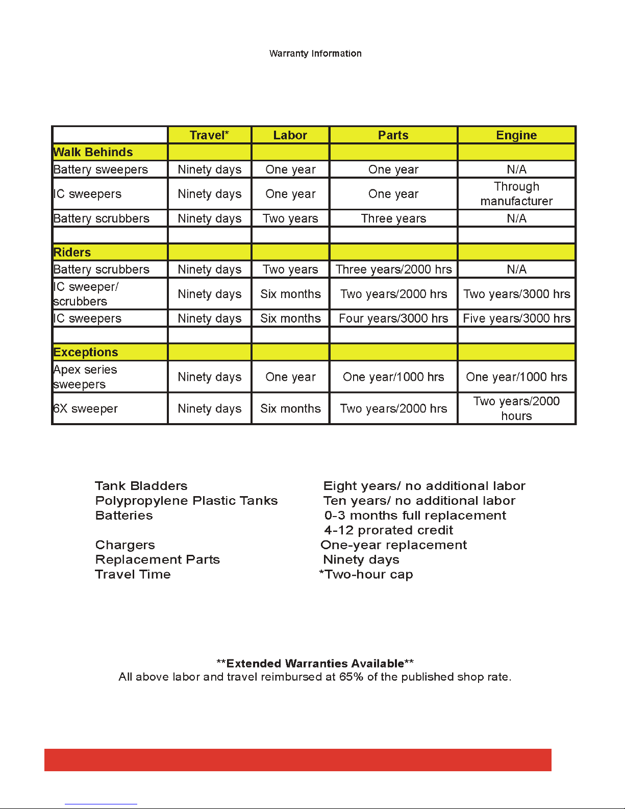
(LIMITED) PRODUCT WARRANTY
PowerBoss, Inc. (hereafter known as PowerBoss) warrants that these PowerBoss machines will be
free from defects in material and workmanship for a period of 24 months or 2,000 operating hours
from date of installation, whichever comes first. Poly components are warranted for five (5) years
unless used with a cleaning solution in excess of 130°F (54°C), which would void the solution and
recovery tank warranty. Written notice of any claimed defect must be given to PowerBoss within the
warranty period and within thirty (30) days after such defect is discovered. Liability under this
warranty is limited to either replacing or repairing, at PowerBoss’s election, any part or parts deemed
defective after examination by PowerBoss or an Authorized Service Representative.
For one hundred eighty (180) days from date of installation, PowerBoss will provide repair labor, at
no charge, solely through an Authorized Service Representative. Thereafter, labor will be charged.
Labor coverage is extended only to those items on which service was performed, and which failed as
a result of defects in materials or workmanship. Normal preventative maintenance or adjustments,
wearable parts, such as but not limited to flaps, filters, seals, points, plugs or similar items are not
eligible for warranty coverage; parts or labor. Brushes are prorated against defects in materials or
workmanship for twelve (12) months; hoses are warranted for six (6) months.
Travel is eligible for warranty consideration the first thirty (90) days after installation. The same
provisions and exclusions apply to travel coverage as to labor and part eligibility.
This warranty does not extend to the PowerBoss machine, or its parts, that have been subject to
misuse, accident or improper handling, installation, maintenance or application, nor does it extend to
PowerBoss machine and/or parts which have been repaired or altered outside PowerBoss’s plant or
the facility of Authorized Service Representative.
Only authorized PowerBoss replacement parts purchased from PowerBoss are eligible for warranty
consideration and are warranted against defects in materials and workmanship for the duration of the
unit’s warranty or thirty (30) days, whichever is longer. (Exception being wearable parts, such as but
not limited to flaps, filters, seals, points, plugs or similar items. These items are to be free of defects
in materials and workmanship when received and are not eligible for additional warranty
consideration.) Damage to the unit, or that incurred as a result of utilization of parts not authorized by
or purchased from PowerBoss, is not eligible for warranty reimbursement; parts or labor.
THE WARRANTY SET FORTH HEREIN IS IN LIEU OF AND EXCLUDES ANY AND ALL OTHER
WARRANTIES, EXPRESS OR IMPLIED, ARISING BY OPERATION OF LAW OR OTHERWISE,
INCLUDING, BUT NOT LIMITED TO, ANY IMPLIED WARRANTY OF MERCHANTABILITY OR
FITNESS FOR A PARTICULAR PURPOSE, AND CUSTOMER WAIVES ANY OBLIGATION OR
LIABILITY OR POWERBOSS ARISING IN TORT OR STRICT LIABILITY IN TORT, OR FOR LOSS
OR USE, REVENUE OR PROFIT WITH RESPECT TO POWERBOSS MACHINE AND/OR PARTS
FOR ANY LIABILITY OF CUSTOMER TO ANY THIRD PARTY, OR FOR OTHER DIRECT,
INCIDENTAL OR CONSEQUENTIAL DAMAGES.
PB # 4100032 / Rev. 01A08
PowerBoss, Inc. Copyright 2008
PAGE 9
PowerBoss® Commander Series Sweeper Scrubber
PowerBoss, Inc. Copyright 2008
PAGE 10
PowerBoss® Commander Series Sweeper Scrubber PB # 4100032 / Rev. 01A08
USERS MANUAL
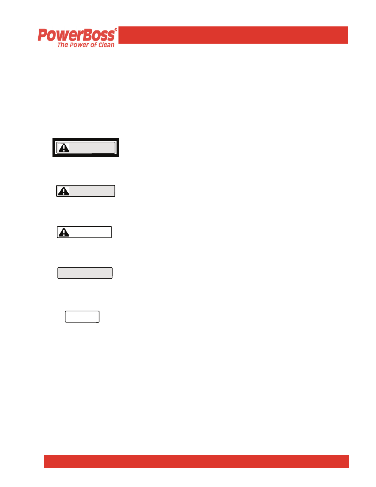
S A F E T Y S Y M B O L S
NOTE
ATTENTION!
CAUTION
WARNING
DANGER
DANGER: To warn of immediate hazards which will
result in severe personal injury or death
WARNING: To warn of hazards or unsafe practices
which could result in severe personal injury or death.
CATUION: To warn of hazards or unsafe practices
which could result in minor personal injury.
ATTENTION!: To warn of practices which could result in
extensive equipment damage.
NOTE: To direct your attention to important equipment
information or special instructions for preventing damage
to equipment
Five symbols are used throughout this manual to emphasize various levels of safety
information. These symbols and the meaning of each are listed below.
Symbols at the top of the list are the strongest warnings. However, all symbols represent
important information which should be observed to protect you and others from harm and
injury, and to prevent damage to the equipment.
PowerBoss, Inc. Copyright 2008
Minuteman PowerBoss, Inc. Copyright 2000
PB # 4100032 / Rev. 01A08
PAGE 11
PAGE 3
PowerBoss® Commander Series Sweeper Scrubber
USERS MANUAL
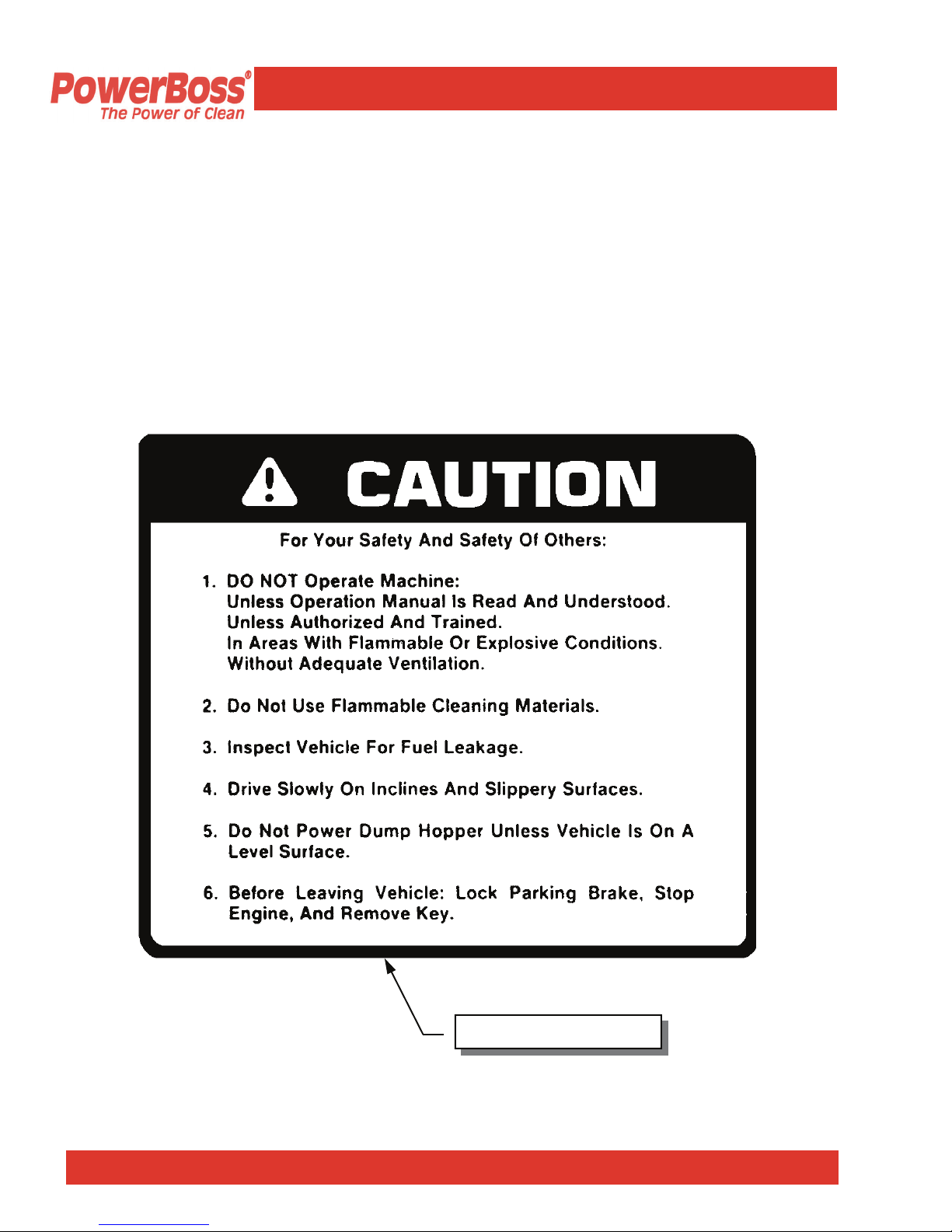
S A F E T Y D E C A L S
Decals directly attached to various parts of the sweeper are highly visible safety
reminders which should be read and observed. Make sure the decals are replaced if they
become illegible or damaged. The decal below is located in the drive compartment. Other
safety decals on you machine appear on the next page.
Part Number 301854
Follow manufacturers recommendations for safe handling of cleaning materials.
PowerBoss, Inc. Copyright 2008
PB # 4100032 / Rev. 01A08
PAGE 12
PowerBoss® Commander Series Sweeper Scrubber

USERS MANUAL
S A F E T Y D E C A L S ( C o n t i n u e d )
Part Number 301728
Located On Shroud
of Radiator
Part Number 301729
Impeller
Part Number 301730
Part Number 301733
Located On Radiator Shroud
Part Number 3301731 Part Number 3301732
Located On Secondary Lift Arm
Located On Lift Arm
Engine Fan
PowerBoss, Inc. Copyright 2008
PAGE 13
PB # 4100032 / Rev. 01A08
PowerBoss® Commander Series Sweeper Scrubber

USERS MANUAL
S A F E T Y
PowerBoss® Sweeper Scrubbers should never be operated unless:
1. The operator is trained and authorized to operate the equipment
2. The equipment is free of malfuntions. Malfunctioning equipment should be removed
from service.
DANGER
WARNING
Keep cigarettes, matches and all other flame sources
away from the sweeper. Gasoline, LP gas and diesel
fuel are highly flammable. Lead acid batteries are
equally dangerous due to the highly explosive
hydrogen gas they emit.
1. Before starting the engine, make sure that:
!
You have read and understand the User Manual.
!
You are securely seated in the operator’s seat.
!
The parking brake is locked.
!
The directional control pedal is in neutral.
!
The throttle is in idle.
!
Hydraulic controls are in the OFF position.
2. During operation:
!
Keep your hands and body clear of moving
parts.
!
Make sure others in the area stay clear of the
equipment and moving parts.
3. When leaving the scrubber unattended:
!
Place the controls in the OFF position.
!
Set the parking brake.
!
Shut off the engine.
PowerBoss, Inc. Copyright 2008
PB # 4100032 / Rev. 01A08
PAGE 14
PowerBoss® Commander Series Sweeper Scrubber

USERS MANUAL
S A F E T Y ( C o n t i n u e d )
4. During cleaning and maintenance:
!
Always stop the engine and set the parking
brake before servicing.
!
Never use detergents or cleansers that are
flammable or combustible.
!
Never inflate a pneumatic tire without using a
safety cage.
!
Never place your hands near the impeller intake
hoses or inlet when the engine is running.
5. When servicing or repairing the fuel system:
!
Work in a properly ventilated area, do not smoke
or allow an open flame near the fuel system.
!
Never bypass safety components unless you are
testing them.
!
Never bypass the fuel filter lock, except when
testing them (and always reconnect them after
testing).
!
Wear gloves to disconnect the LPG tank
coupling.
6. Do not operate an LPG powered scrubber when
any component in the fuel system is
malfunctioning or leaking.
7. Replace any defective safety components before
operating the scrubber.
CAUTION
PowerBoss, Inc. Copyright 2008
PB # 4100032 / Rev. 01A08
PAGE 15
PowerBoss® Commander Series Sweeper Scrubber

USERS MANUAL
S A F E T Y ( C o n t i n u e d )
1. Travel slowly on grades. NEVER EXCEED 8º
2. Place a block or chock behind the wheels when
parking on inclines.
3. Use special care when traveling on wet surfaces.
Observe all proper procedures for operation and
maintenance of the scrubber, as outlined in this
manual.
4. Remain alert at all times to people and equipment
in and around your area of operation.
Turn the tow valve before pushing or towing.
Never push or tow a machine faster than specified.
ATTENTION!
WARNING
PowerBoss, Inc. Copyright 2008
PB # 4100032 / Rev. 01A08 PowerBoss® Commander Series Sweeper Scrubber
PAGE 16

USER OPERATIONS
IGNITION
SWITCH
STARTING
GAS / LP
HORN
FUEL LEVEL GAUGE
BATTERY / AMPERAGE
GAUGE
HOUR METER
ENGINE OIL
PRESSURE
ENGINE COOLANT
TEMPERATURE GAUGE
STARTING
DIESEL
The three position key switch is used to turn the machine’s
power on and off.
To start gasoline & LP powered machines, turn the key clockwise
to the START position. When the engine starts, release the key.
To stop the engine, turn the key counter clockwise to the OFF
position.
The horn is activated by pressing the horn button located on the
right side of the instrument panel. Next to the ignition switch.
The fuel gauge indicates the amount of fuel remaining in the tank
for gasoline & diesel units.
A battery gauge is used on LP & Gasoline units. It indicates the
voltage being sent to the battery by the alternator. 13.5v is
normal. An Amp. Gauge is used on diesel units, It indicates a
charge or discharge of current to the battery.
The hour meter records the number of hours the machine has
been operated, providing a helpful guide for performing routine
maintenance tasks.
The engine oil pressure gauge ranges from 0 psi to 60 psi. A
reading below 7 psi indicates problems, which may result in
damage to the engine.
The engine coolant temperature gauge registers the temperature
of the engine coolant. Temperatures above 220°F indicate an
overheating engine.
The Kubota V1505 engine is equipped with 4 glow plugs to aid in
cold starting. To start a cold engine:
! Turn the ignition key clockwise and hold the glow plug button
located on the left side of the instrument panel for 10 - 20
seconds to warm the glow plugs.
! Turn the key clockwise to the START position until the engine
starts.
! When the engine starts, release the key.
If the engine does not start after 10 seconds, release the key,
wait 1 minute and repeat the procedure.
OP E R AT I O N A ND C O N TR O L S
NOTE
PowerBoss, Inc. Copyright 2008
PB # 4100032 / Rev. 01A08
PAGE 17
PowerBoss® Commander Series Sweeper Scrubber

PAGE 18
PowerBoss, Inc. Copyright 2008
PowerBoss® Commander Series Sweeper Scrubber
PB # 4100032 / Rev. 01A08
USER OPERATIONS
THROTTLE
DIRECTIONAL
CONTROL PEDAL
PARKING BRAKE
The throttle adjusts the engine speed from idle to the
operating speed.
! The throttle should be in the IDLE position when
starting the engine and immediately before shutdown.
! The throttle should be in the RUN position during
normal operation to ensure proper broom speed.
The directional control pedal controls the speed and
direction of the machine. It is also used for slowing the
machine or stopping.
! To propel the machine forward, apply pressure to the
front of the pedal, increasing pressure to increase
speed.
! To propel the machine backward, apply pressure to
the rear of the pedal.
! To slow or stop the machine, move the foot pedal into
neutral.
! For emergency stops move the foot pedal past neutral
and into the opposite position.
Use for emergency stops only! Constant use of this
braking method may result in damage to the drive
components.
On Optional and Deluxe models, the hand brake is
engaged by lifting up on the lever.
The parking brake operates the mechanical drum brakes
on the front two wheels and is engaged by the brake pedal.
! Diesel units equipped with a handbrake is standard.
! Hydraulic brakes are optional and includes a
handbrake
OP E R AT I O N A ND C O N TRO L S
NOTE

BROOM CONTROLS
SIDE BROOM
OPTIONAL
ON C82 & C90
SIDE BROOM
HANDLE
MAIN BROOM
SCRUB BRUSHES
The broom control lever activates the hydraulic brush circuit.
Side broom OFF position is achieved by placing the lever on the
control valve in the rear portion of the slot. When the side broom is
OFF the scrub brushes & Main Broom will still be ON.
The side broom is used to move debris from the wall edges to the
path of the main sweeping broom.
The side broom handle located to the right of the instrument panel
on the lintel raises and lowers the side broom.
Brooms and Brushes may be raised & lowered independently.
By placing the broom control lever in the center of the slot. All
broom motors are deactivated.
! When not sweeping, the side broom should remain in the RAISE
position.
! To lower the side broom position the handle to the
LOWER position of the slot
The Main broom raises and lowers via the handle located left of the
instrument panel on the lintel. The decal shows 3 positions,
“RAISE, NORMAL & FLOAT”
FLOAT POSITION SHOULD ONLY BE USED WHEN THE
SURFACE IS EXTREMELY UNEVEN! Frequent use of this position
will reduce the main broom life.
To operate the scrub brushes, follow these steps:
1. Activate the scrub brushes by putting the broom and brush
hydraulic control lever in the ON position.
2. Lower the scrubhead to the floor with the scrubhead rocker
switch located on the console left of the operator. Press to
“Lower” Position. Scrubhead is raised by same switch. Press to
“Raise” position.
*The scrubhead gauge is a visual indication of the scrub
deck position and not the amount of pressure on the floor.
O P E R AT ION AND C O N T ROL S
NOTE
NOTE
NOTE
USER OPERATIONS
NOTE
NOTE
PowerBoss, Inc. Copyright 2008
PAGE 19
PowerBoss® Commander Series Sweeper Scrubber PB # 4100032 / Rev. 01A08

HOPPER
CONTROLS
HOPPER RAISE
HOPPER LOWER
HOPPER ROTATE
DUMP
HOPPER ROTATE
RETURN
RTR FUNCTION
C82 & C90
MANUAL HOPPER
REMOVAL
On Commander Series T82 & T90 The Hopper is hydraulically
controlled. The broom control lever must be in the off position to
use hopper controls, There are Three levers Grouped together located
on the lintel connecting a hydraulic valve. Two spools on the control
valve activates The hopper Lift, Lower & Rotation functions. These
Spools are Inside A Red Outline On The Decal Marked “High Dump”
NEVER GET BENEATH A RAISED HOPPER WITHOUT SAFETY
ARM IN PLACE!
TO RAISE HOPPER; With engine Running, Pull Back On Lever On Far
Left To “Raise” Position. Release Lever @ desired Height. Hopper Will
Stop At That Position.
TO LOWER HOPPER; Push Lever On Far Left To The “Lower”
Position. Hopper Should Rest On Stops.
The Engine Does Not Have To Be Running To Lower Hopper.
TO ROTATE HOPPER; With Engine Running And Hopper Raised, Pull
Back On The Center Lever To The “Dump” Position, Hopper Will
Rotate Out.
TO RETURN HOPPER; With Engine Running Push The Center Lever
Forward To The “Return” Position, Hopper Will Rotate Back.
RTR LIGHTS; “Rotary Trash Relocation”
Located On The Upper Left Of The Instrument Panel Are Two Red
Lights Marked # 1 & # 2. These Lights Are Indicators For Hopper Height.
And Trash Location.
Light # 1 When Illuminated Indicates Hopper Is At A Safe Height To
Rotate The Hopper Clearing The Frame To Relocate Trash To The
Front Of Hopper. This Will Clear The Hopper Loading Opening.
Light # 2 When Illuminated Indicates Hopper Is At A Height Of 61.0” For
Dumping Into A Standard Dumpster.
Turn The Machine OFF And Set The Parking Brake.
Always Use Proper Lifting Techniques
1. Grasp the handles on top of the hopper.
2. Lift the hopper straight up, about 3 inches (76.2 mm) until the support
brackets clear the frame.
3. Remove the hopper and dump debris.
4. Replace the hopper.
O P E R ATIO N AND C O N T RO L S
USER OPERATIONS
WARNING
CAUTION
PowerBoss, Inc. Copyright 2008
PAGE 20
PowerBoss® Commander Series Sweeper Scrubber PB # 4100032 / Rev. 01A08

STARTING SOLUTION
FLOW
FILLING THE
SOLUTION TANK
To fill the solution tank follow these steps:
1. Park the machine on a level area and lock the parking brake.
2. Make sure the solution delivery valve is closed via the solution
lever.
3. Open the top door of the machine and remove the plug @ the
Auto fill Assembly. Connect a garden hose to the AutoFill
Assembly. Turn on faucet for clean water solution. The water
will shut off when the proper level is achieved. Disconnect
garden hose replace the plug @ auto fill connector and close
top door.
OR
Unscrew the smallest (6 inch) cap located on the top of the
solution tank. Fill the tank with cleaning water solution.
When the tank is full, close the door and replace the cap.
Never use detergents or cleaners that are flammable or
combustible. Always wear safety glasses and protective
clothing when using chemicals of any kind.
It is recommended to use PowerBoss chemicals which are
specially formulated for use in power scrubbers.
O P E RATIO N AND C O N TRO L S
CAUTION
USER OPERATIONS
Start the flow of solution to the floor by;
!" Moving the solution lever located on the console left
of the operator. Move the lever towards the front of
unit, adjusting to the desired amount of flow. This is a
gravity feed system. Maximum flow is 3 gpm.
Drive Forward Slowly Use care when driving on wet surfaces. Always travel slowly on grades.
CAUTION
PowerBoss, Inc. Copyright 2008
PAGE 21
PowerBoss® Commander Series Sweeper Scrubber PB # 4100032 / Rev. 01A08

SQUEEGEE
IMPELLER
DRAINING THE
RECOVERY TANK
To Lower The Squeegee;
Press the rocker switch marked “SQUEEGEE” to the
Lower Position. This switch is located on the console to the
left of the operator
*When using the squeegee or scrubbing with the unit, the
throttle cable (standard for diesel) or (rocker switch standard for LP & Gasoline) engines should be @ the high position for maximum engine Rpm’s with Impeller on.
To Turn On Vacuum Impeller;
To the left of the operator on the console is a single lever
marked “Impeller” move lever forward to the to the on
position.
Follow These Steps To Drain Recovery Tank:
1. Park the machine on a level surface at an approved
drainage site with the left rear of the machine beside the
drain access.
2. Engage the parking brake.
3. Turn the machine OFF.
4. Open the left scrubhead access door.
5. Remove the flexible drain hose from its storage hook.
Pull out the drain hose for the required reach to the
access.
6. Place the end of the drain hose on or in the approved
drain access.
7. Loosen and remove the drain plug.
8. Drain the tank completely and reinstall the plug.
9. Reposition the drain hose on its storage hook.
O P E R AT I O N A N D C O N T R O L S
USER OPERATIONS
NOTE
PowerBoss, Inc. Copyright 2008
PAGE 22
PowerBoss® Commander Series Sweeper Scrubber PB # 4100032/ Rev. 01A08
 Loading...