

PowerBoss Armadillo SW/9XR, Armadillo SW/9XV User Manual
USER MANUAL
ARMADILLO® SWEEPER
SW/9XR / SW/9XV
PowerBoss, Inc.
A Member Of The Hako Group
PB# 4100033 Rev. 01A08

Operation, Maintenance and Troubleshooting
The Model and Serial Numbers of your machine are shown on the nameplate mounted on the
machine. This information is needed when contacting Technical Support or ordering parts.
For your convenience, use the space below to record the Model and Serial Numbers of your
machine and the date it was placed into service.
MODEL NUMBER: ___________________________________________
SERIAL NUMBER: ___________________________________________
DATE PLACED INTO SERVICE: _______________________________
Contact:
techsupport@powerboss.com
All information contained in this manual is current at the time of printing. However, due to constant updates and improvements, we reserve the right to make changes at any time without notice.
© Copyright 2008, Minuteman PowerBoss, Inc.
All rights reserved. This manual may not be copied or reproduced in any form, without the written permission of Minuteman PowerBoss, Inc.
PowerBoss, Inc. Copyright 2008
PowerBoss, Inc. Copyright 2008
PB # 4100033 / Rev. 01A00
Page #1
Armadillo® SW/9XR & SW/9XV PB # 4100033 / Rev. 01A00
Armadillo® SW/9XR & SW/9XV

OPERATION,
AINTENANCE &
M
ROUBLESHOOTING
T
SW/9XR
SW/9XV
TABLE OF CONTENTS
Features .............................................................................. 7
Limited Warranty .................................................................8
SAFETY
Safety Symbols .................................................................... 9
Safety Decals ................................................................10-11
Basic PowerBoss
OPERATION
Basic Operating Controls ................................................15-16
Sweeping Controls ............................................................. 17
Debris Hopper Dump Controls ............................................. 18
Operating Procedures
Pre-Operation Check .......................................... 19
Starting ............................................................ 19
Slowing and Stopping ......................................... 20
Operating on Grades........................................... 20
Sweeping .......................................................... 20
Emptying the Hopper.......................................... 20
Using the Rotary Trash Relocator (RTR™) ............. 21
Transporting the Machine ................................... 22
®
Safety .................................................12-14
PowerBoss, Inc. Copyright 2008
Page 3
Armadillo® SW/9XR & SW/9XV PB # 4100033 / Rev. 01A00

Operation, Maintenance and Troubleshooting
TABLE OF CONTENTS (Continued)
MAINTENANCE
Introduction....................................................................... 23
Planned Maintenance Chart
Engine .............................................................. 24
Air Intake System .............................................. 24
Electrical System ............................................... 24
Coolant System .................................................. 24
Hydraulics System.............................................. 25
Sweep Components.............................................25
Hopper.............................................................. 26
Steering ............................................................ 26
Parking Brake .................................................... 26
Tires ................................................................ 27
Miscellaneous .................................................... 27
Impeller............................................................27
Service Instructions
Engine .............................................................. 28
Air Intake
Filter Removal...........................................29
Filter Cleaning ..........................................29
Filter Inspection ........................................29
Filter Installation.......................................29
Electrical System
Battery Cleaning........................................30
Battery Replacement................................... 30
Circuit Breakers.........................................30
Fuses........................................................30
Fuel System
WARNINGS.............................................. 31
Tier װ Compliancy ....................................... 31
Coolant System
Blowing Out Radiator Fins .......................... 32
Reverse Flow Flushing................................33
Lubrication
Changing Engine Oil ..................................33
Lubrication Points...................................... 34
Hydraulics System
Filling the Fluid Reservoir .......................... 35
Changing the Hydraulic Fluid ......................35
Changing the Hydraulic Fluid Filter .............36
Adjusting the Directional Control
Return Spring ....................................... 36-37
PowerBoss, Inc. Copyright 2008
Page 4
Armadillo® SW/9XR & SW/9XV PB # 4100033 / Rev. 01A00

Operation, Maintenance and Troubleshooting
TABLE OF CONTENTS (Continued)
MAINTENANCE (CONTINUED)
Sweep Components
Broom Door Flap Inspection........................ 38
Broom Door Flap Replacement
and Adjustment..........................................38
Main Broom Adjustment..............................38
Main Broom Height Adjustment ...................39
Main Broom Taper Adjustment.....................40
Main Broom Replacement............................ 41
Side Broom Angle Adjustment ..................... 42
Side Broom Height (Wear) Adjustment.......... 42
Side Broom Replacement............................. 43
Hopper
Hopper Removal ........................................44
Hopper Replacement...................................44
Filter Removal........................................... 45
Filter Cleaning ..........................................45
Filter Replacement .....................................45
Floor Clearance and Dump Adjustments ........ 46
Adjusting Maximum Hopper Dump Angle ......47
Vacuum Gasket Mount Adjustment ...............47
Flap Replacement.......................................48
Frame Seal Replacement
Front Frame Seal................................ 48
Side Frame Seal ................................. 48
Parking Brake .................................................... 49
Tires
Changing Solid Tires ..................................50
Changing Pneumatic Tires ...........................50
Miscellaneous Adjustments
Anti-Static Chain ....................................... 51
Latches and Hinges .................................... 51
Cables ...................................................... 51
PowerBoss, Inc. Copyright 2008
Page 5
Armadillo® SW/9XR & SW/9XV PB # 4100033 / Rev. 01A00

Operation, Maintenance and Troubleshooting
TABLE OF CONTENTS (Continued)
TROUBLESHOOTING
Basic Machine Operating Problems
Engine will not start or runs roughly after start ............. 52
Engine overheats ....................................................... 53
PowerBoss
PowerBoss
Sweeping Problems
Brushes do not turn or turn very slowly ........................ 54
Little or no vacuum in brush compartment..................... 55
Loss of dust control ................................................... 55
Sweeper unit leaving debris .................................... 55-56
Hopper does not raise or lower .................................... 56
Hopper does not rotate or rotates slowly ....................... 57
Hydraulic System Problems
Hopper lift cylinder failure ......................................... 57
Hydraulic motor failure .............................................. 58
Hydraulic gear pump failure ........................................ 58
Hydraulic variable displacement pump failure ............... 59
Hydraulic system noisy............................................... 60
Your page ....................................................................... 61
Notes …………………………………………………………………….62
Electrical Schematic Kubota V1505……………..………………….63
Electrical Schematic GM 1.6L ............................................. 64
Hydraulic Schematic 9XR ................................................... 65
Hydraulic Schematic 9XV .................................................. 66
Warranty Matrix ................................................................ 67
®
moves slowly or does not move .................. 53
®
creeps in neutral ...................................... 54
PowerBoss, Inc. Copyright 2008
Page 6
Armadillo® SW/9XR & SW/9XV PB # 4100033 / Rev. 01A00

Operation, Maintenance and Troubleshooting
SW/9XV
FEATURES
1. Dust Control Filter: 104 Sq. Ft. total
2. Timed Electric Filter Shakers
3. Shock-mounted Hydraulic Impeller
4. Power Steering with Tilt Steering Wheel
5. Adjustable Seat
6. Exhaust Air Expelled Outside Engine
7. Industrial Liquid-Cooled Engine
8. 4-Core Radiator
9. Tri-Phase Air Cleaner
10. Built-In Dust PreFiltering
11. One-Piece Unitized Steel Frame
12. Clogged Filter Indicator
13. Hydraulics Protection Package
14. Dual Performance Sweep Mode
15. Quick-Change Floating 48” Main Broom
16. PowerClimb™ All-Terrain Access
(Two 23” OD Pneumatic Front Tires & One 21” OD Pneumatic Rear Tire)
17. Oversized Hopper with RTR™
18. Retractable Quick-Change Side Broom
19. Multi-Level Hopper Dumping
20. Fire-in-hopper Indicator
PowerBoss, Inc. Copyright 2008
Page 7
Armadillo® SW/9XR & SW/9XV PB # 4100033 / Rev. 01A00

Operation, Maintenance and Troubleshooting
SW/9XR
SW/9XV
LIMITED PRODUCT WARRANTY
PowerBoss, Inc. warrants that the PowerBoss SW/9XR & SW/9XV will be free from defects in material and
workmanship for a period of 48 months or 2,800 operating hours from date of installation, whichever comes
first. Written notice of any claimed defect must be given to PowerBoss within the warranty period and within
thirty (30) days after such defect is discovered. Liability under this warranty is limited to either replacing or
repairing, at PowerBoss’s election, any part or parts deemed defective after examination by PowerBoss or an
Authorized Service Representative. The PowerBoss machine or any of its parts returned by customer to PowerBoss or an Authorized Service Representative via prepaid transportation and which is found to be defective,
will be repaired or replaced and returned to customer via prepaid surface transportation within the Continental
US. One the other hand, should a part be found not defective, inspection and handling charges may be charged
to the customer my PowerBoss or an Authorized Service Representative.
For one hundred eighty (180) days from date of installation, PowerBoss will provide repair labor, at no charge,
solely through an Authorized Service Representative. Thereafter, labor will be charged.
This warranty does not extend to the PowerBoss machine, or its parts, that have been subject to misuse, accident or improper handling, installation, maintenance or application, nor does it extend to PowerBoss machine
and/or parts which have been repaired or altered outside PowerBoss’s plant or the facility of Authorized Service Representative.
This warranty does not apply to routine wearable parts of the PowerBoss machine such as brushes, flaps, filters, seals, point, plugs, hoses or similar items. Moreover, this warranty does not extend to the PowerBoss machine or part replaced or repaired under this warranty.
Only replacement parts supplied by PowerBoss are warranted for 30 days after installation.
The warranty for optional engines shall be limited to the warranty extended to PowerBoss by the supplier.
ENGINE WARRANTY LIMITAT ION
For the 25th through 60th month, or from 2,000 hours through 3,000 hours, whichever comes first, only the
following engine components shall be covered under the parts warranty:
-Cylinder Block -Intake Manifold
-Cylinder Head -Connecting Rods
-Camshaft
THE WARRANTY SET FORTH HEREIN IS IN LIEU OF AND EXCLUDES ANY AND ALL OTHER
WARRANTIES, EXPRESS OR IMPLIED, ARISING BY OPERATION OF LAW OR OTHERWISE, INCLUDING, BUT NOT LIMITED TO, ANY IMP LIED WARRANTY OF MERCHANTABILITY OR FITNESS FOR A PARTICULAR PURPOSE, AND CUSTOMER WA IVES ANY OBLIGATION OR LIABILITY OR POW ERBOSS ARIS ING IN TORT O R STRICT LIA BILITY IN TORT, OR FOR LOSS OR US E,
REVENUE OR PR OFIT WITH R ESPECT TO PO WERBOSS MACH INE AND/OR PARTS FOR ANY LIABILITY OF CUSTOMER TO ANY TH IR D PA RT Y, OR FOR OT HER D IRE CT, INCIDENTAL OR CON SEQUENTIAL DAMAGES.
PowerBoss, Inc. Copyright 2008
Page 8
Armadillo® SW/9XR & SW/9XV PB # 4100033 / Rev. 01A00
Operation, Maintenance and Troubleshooting
Five symbols are used throughout this manual to emphasize various levels of safety information.
These symbols and the meaning of each are listed below.
DANGER
WARNING
CAUTION
ATTENTION!
Symbols at the top of the list are the strongest warnings. However, all symbols represent important
information which should be observed to protect you and others from harm and injury, and to prevent
damage to the equipment.
NOTE
SAFETY SYMBOLS
DANGER: To warn of immediate hazards which will result
in severe personal injury or death
WARNING: To warn of hazards or unsafe practices which
could result in severe personal injury or death.
CATUION: To warn of hazards or unsafe practices which
could result in minor personal injury.
ATTENTION!: To warn of practices which could result in
extensive equipment damage.
NOTE: To direct your attention to important equipment information or special instructions for preventing damage to
equipment
PowerBoss, Inc. Copyright 2008
Page 9
Armadillo® SW/9XR & SW/9XV PB # 4100033 / Rev. 01A00
Operation, Maintenance and Troubleshooting
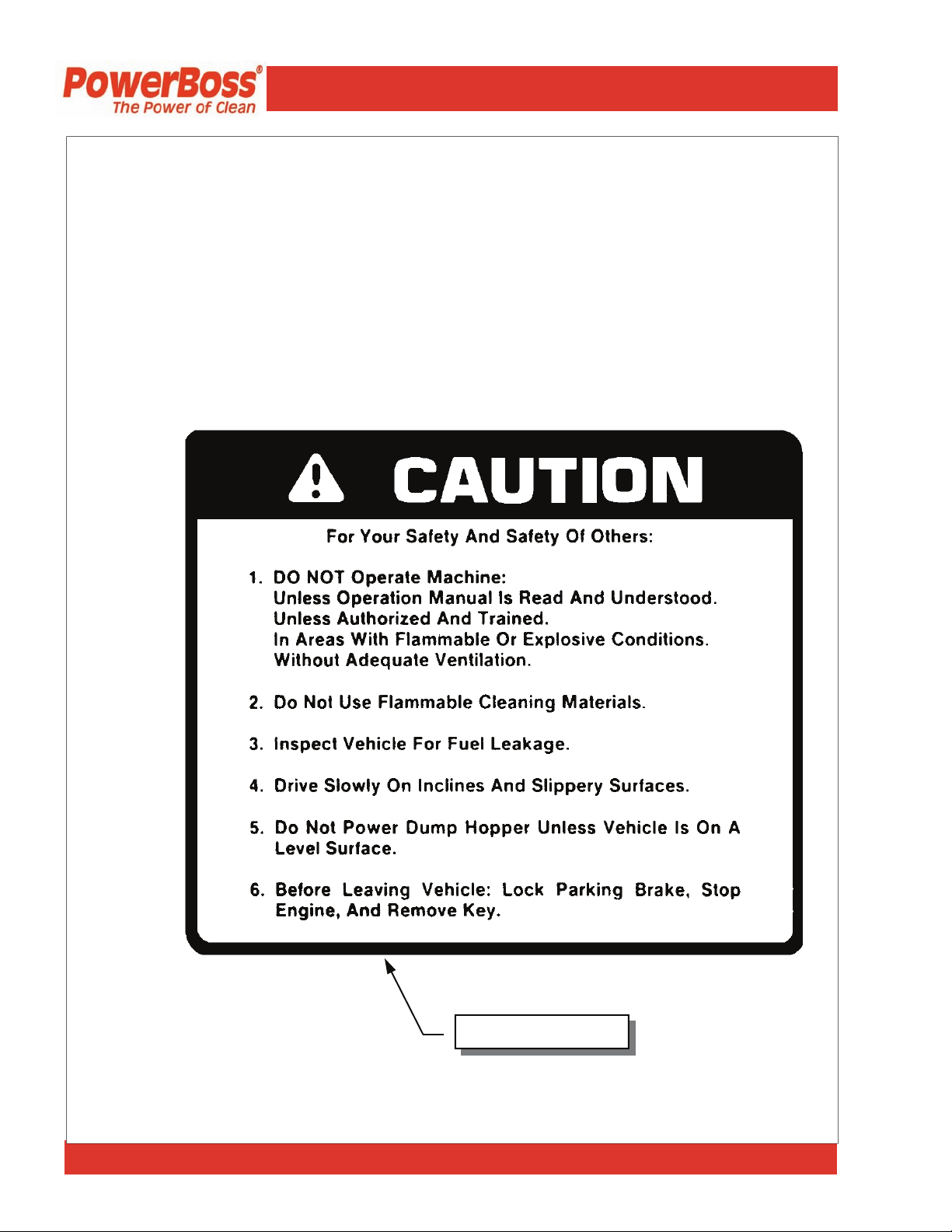
SAFETY DECALS
Decals directly attached to various parts of the sweeper are highly visible safety reminders which
should be read and observed. Make sure the decals are replaced if they become illegible or damaged. The decal below is located in the drive compartment. Other safety decals on you machine
appear on the next page.
PowerBoss, Inc. Copyright 2008
Part Number 301854
Page 10
Armadillo® SW/9XR & SW/9XV PB # 4100033 / Rev. 01A00
Operation, Maintenance and Troubleshooting
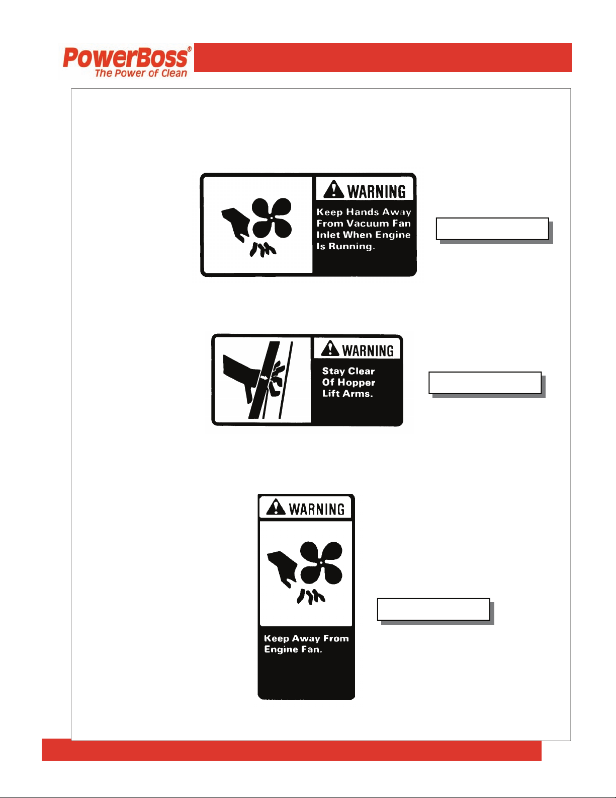
SAFETY DECALS (Continued)
Located at the Impeller:
Part Number 301729
Located on the High Dump Hopper:
Located on the Shroud of the Radiator:
Part Number 301733
Part Number 301732
PowerBoss, Inc. Copyright 2008
Page 11
Armadillo® SW/9XR & SW/9XV PB # 4100033 / Rev. 01A00
Operation, Maintenance and Troubleshooting
BASIC PowerBoss® SAFETY
PowerBoss® sweepers should never be operated unless: 1. The operator is trained and authorized
to operate the equipment and, 2. The equipment is free of malfuntions. Malfunctioning equipment
should be removed from service.
1. Keep cigarettes, matches and all other flame sources
DANGER
equally dangerous due to the highly explosive
hydrogen gas they emit.
WARNING
٭ The parking brake is locked.
2. During operation:
expecially when the hopper or lift arms are partially
or fully raised.
and moving parts.
Dump from ground level only.
3. When leaving the sweeper unattended:
away from the sweeper. Gasoline, LP gas and diesel
fuel are highly flammable. Lead acid batteries are
1. Before starting the engine, make sure that:
٭
You are securely seated in the operator’s seat.
٭
The directional control pedal is in neutral.
٭
The throttle is in idle.
٭
Hydraulic controls are in the OFF position.
٭
Keep your hands and body clear of moving parts,
٭
Make sure others in the area stay clear of the equipment
٭
Never attempt to dump debris from a dock or mezzanine.
٭
Place the controls in the OFF position.
٭
Set the parking brake.
٭
Shut off the engine.
PowerBoss, Inc. Copyright 2008
Page 12
Armadillo® SW/9XR & SW/9XV PB # 4100033 / Rev. 01A00

Operation, Maintenance and Troubleshooting
BASIC PowerBoss® SAFETY (Continued)
4. During cleaning and maintenance:
before servicing.
or combustible.
cage.
shut off the engine. Never place your hands near
the intake hoses or inlet when the engine is running.
hopper. Do not rely on the hydraulic cylinder to
keep the hopper raised.
any other part of your body. High pressure leaks can be
very dangerous and should only be checked using a piece
or paper.
5. When servicing or repairing the fuel system:
allow an open flame near the fuel system.
them.
them (and always reconnect them after testing).
6. Do not operate an LPG powered sweeper when any
component in the fuel system is malfunctioning or leaking.
7. Replace any defective safety components before operating
the sweeper.
CAUTION
dumpster or receptacle. Driving with the hopper raised
reduces visibility and creates conditions for striking over head objects, throwing the machine off-balance and other
hazards.
1. Do not drive with the hopper in the raised position except
the few feet necessary to position the hopper over the
٭
Always stop the engine and set the parking brake
٭
Never use detergents or cleansers that are flammable
٭
Never inflate a pneumatic tire without using a safety
٭
Do not attempt any impeller adjustment unless you have
٭
Always engage the safety arm before servicing the
٭
Never test for hydraulic hose leaks using your hand or
٭
Work in a properly ventilated area, do not smoke or
٭
Never bypass safety components unless you are testing
٭
Never bypass the fuel filter lock, except when testing
٭
Wear gloves to disconnect the tank coupling.
PowerBoss, Inc. Copyright 2008
Page 13
Armadillo® SW/9XR & SW/9XV PB # 4100033 / Rev. 01A00

Operation, Maintenance and Troubleshooting
BASIC PowerBoss® SAFETY (Continued)
2. Travel slowly on grades.
3. Place a block or chock behind the wheels when parking on
inclines.
4. Use special care when traveling on wet surfaces.
5. Observe all proper procedures for operation and
maintenance of the sweeper, as outlined in this manual.
6. Remain alert at all times to people and equipment in and
around your area of operation.
1. Do not operate the #2 RTR lever before the #1 light
ATTENTION!
2. Never push or tow a machine faster than 6 mph.
illuminates.
PowerBoss, Inc. Copyright 2008
Page 14
Armadillo® SW/9XR & SW/9XV PB # 4100033 / Rev. 01A00

Operation, Maintenance and Troubleshooting
BASIC OPERATING CONTROLS
IGNITION SWITCH
STARTER
NOTE
HORN
FUEL LEVEL
GAUGE
VOLTMETER
AMP GAUGE
HOUR METER
ENGINE OIL
PRESSURE
ENGINE COOLANT
TEMPERATURE
GAUGE
The diesel powered machine has a two position key switch used to turn
the machine’s electric power on and off. The gasoline and LP units have
a three position key switch.
To start gasoline powered machines, turn the key clockwise to the Start
position When the engine starts, release the key. To stop the engine, turn
the key to OFF.
To start diesel engines, turn the ignition key clockwise to the on position.
Press the Glow Plug Button for 20 seconds. Continue turning
ignition key clockwise to the Start position. When engine starts release
key.
If the engine does not start after 10 seconds, release the key,
wait 1 minute and repeat the procedure.
The horn is activated by pressing the horn button located on the right side
of the operator.
The fuel gauge indicates the amount of fuel remaining in the tank.
The Voltmeter used on gas & LP units or Amp Gauge used on diesel
units indicates the charging current which is being sent to the battery by
the alternator. It also indicates a drop in voltage when the alternator is not
charging.
The hour meter records the number of hours the machine has been operated, providing a helpful guide for performing routine maintenance tasks.
The engine oil pressure gauge ranges from 0 psi to 60 psi. A reading below 7 psi indicates problems which may result in damage to the engine.
The engine coolant temperature gauge registers the temperature of the
engine coolant. Temperatures above 220°F indicate an overheating engine.
PowerBoss, Inc. Copyright 2008
Page 15
Armadillo® SW/9XR & SW/9XV PB # 4100033 / Rev. 01A08

Operation, Maintenance and Troubleshooting
Operation, Maintenance and Troubleshooting
BASIC OPERATING CONTROLS (Continued)
THROTTLE
DIRECTIONAL
CONTROL PEDAL
CAUTION
PARKING BRAKE
The throttle adjusts the engine speed from idle to the operating
speed.
• The throttle should be in the IDLE position when starting the
engine and immediately before shutdown.
• Full throttle position should be used during operation to en-
sure proper broom speed and dust control.
The directional control pedal controls the speed and direction of
the machine. It is also used for slowing the machine or stopping.
• To propel the machine forward, apply pressure to the front of
the pedal, increasing pressure to increase speed.
• To propel the machine backward, apply pressure to the rear of
the pedal.
• To slow or stop the machine, move the foot pedal into neutral.
• For emergency stops, move the foot pedal past neutral and
into the opposite position.
Use for emergency stops only! Constant use of this braking
method may result in damage to the drive components.
The sweeper is equipped with a speed limiter. A stop is mounted
under the directional control pedal and can be raised to reduce the
maximum speed.
The hydraulic drum brakes on the two front wheels are operated
by pressing on the brake pedal. The parking brake is cable activated. To engage the parking brake pull upward on the hand
brake lever located on the left side of the front wall of the operator’s compartment.
PowerBoss, Inc. Copyright 2008
Page 16
Armadillo® SW/9XR & SW/9XV PB # 4100033 / Rev. 01A08

Operation, Maintenance and Troubleshooting
SWEEPING CONTROLS
BROOM CONTROL
LEVER
NOTE
NOTE
MAIN BROOM
HANDLE
NOTE
SIDE BROOM
HANDLE
The broom control lever activates the brooms. (“Side Broom
OFF” position activates the main broom only.)
The main broom and side broom may be lowered independently.
The “OFF” position is achieved by placing the broom control
lever in the center of the slot. Both broom motors (main &
side) are de-activated by taking this action.
The main broom handle to the immediate left of the driver raises
and lowers the main broom. For normal sweeping, position the
handle at the LOWER position on the handle slot.
• For extremely uneven floor, position the handle at the
FLOAT position on the handle slot.
Extensive use of the FLOAT position reduces broom life.
• When not sweeping, position and lock the handle to the
RAISE position on the handle slot.
The side broom handle to the immediate left of the driver raises
and lowers the side broom.
• When not sweeping, the side broom should remain in the
RAISE position.
• To lower the side broom, position the handle to the LOWER
position in the handle slot.
PowerBoss, Inc. Copyright 2008
Page 17
Armadillo® SW/9XR & SW/9XV PB # 4100033 / Rev. 01A08

Operation, Maintenance and Troubleshooting
DEBRIS HOPPER DUMP CONTROLS
HOPPER FILTER
SHAKER BUTTON
CAUTION
HIGH DUMP
MODELS
ROTARY TRASH
RELOCATOR
(RTR™)
This button is used to activate the filter shakers prior to dumping
or as needed during sweeping operation. It is located to the left
hand side of the instrument panel.
To shake the filter:
1. Bring the machine to a complete stop.
2. Place the broom control lever in the OFF position.
3. Press and hold the filter shaker button for 20 to 30 seconds.
4. Place the broom control lever in the ON position and resume
sweeping.
Do not leave the hopper in the RAISE position for an extended
period of time.
The two far left levers on the front of the control panel are used to
raise the hopper to any height up to 60” (1.52 m) and dump it.
• To raise the hopper, pull back Lever 1 to the RAISE position
and hold until the hopper raises to the proper height for the
dumpster or container.
• To empty debris, pull back Lever 2 to the DUMP position to
rotate the hopper forward and empty the debris.
• To rotate the hopper back, push Lever 2 forward to the
RETURN position until the hopper rotates and stops.
• To lower the hopper, push Lever 1 forward to the LOWER
position until the hopper stops.
Rotary Trash Relocator (RTR™) is a standard feature on highdump models. Its purpose is to increase the holding capacity of
the debris hopper to make dumping the hopper necessary less frequently.
PowerBoss, Inc. Copyright 2008
Page 18
Armadillo® SW/9XR & SW/9XV PB # 4100033 / Rev. 01A08
Operation, Maintenance and Troubleshooting
OPERATING PROCEDURES
PRE-OPERATION
CHECKS
STARTING
WARNING
CAUTION
Prior to starting the engine, check the following:
1. Engine oil level
2. Engine coolant level
3. Fuel level
4. Hydraulic fluid level
5. Brakes, steering and directional controls
6. The floor beneath the machine for signs of fluid leaks
Fluid levels should be correct. Brakes, steering and directional
controls should be functioning properly. Hoses, lines and tanks
should be free of damage and leaks.
Before starting the engine, sit in the operator’s seat and make
sure the parking brake is locked.
1. Make sure the directional control pedal is in the neutral position.
2. Make sure the throttle is in the idle position.
3. Gasoline-powered: Turn the ignition key to the ON position,
push the button located just below the key. When the engine
starts, release the button. If the engine is cold, pull out the
choke knob and repeat the above procedure. When the engine
is running smoothly, push the choke knob in.
If the engine fails to start, do not continue cranking for more
than ten seconds. Allow the starter motor to cool between
attempts.
4. Move the machine forward or backward as follows:
• Forward: Apply pressure to the front of the directional con-
trol pedal, increasing pressure to increase speed.
• Reverse: Apply pressure to the rear of the pedal, increasing
pressure to increase speed.
PowerBoss, Inc. Copyright 2008
Page 19
Armadillo® SW/9XR & SW/9XV PB # 4100033 / Rev. 01A08

Operation, Maintenance and Troubleshooting
SLOWING AND
STOPPING
OPERATING ON
GRADES
SWEEPING
NOTE
EMPTYING THE
HOPPER
High Dump
Models
1. Allow the directional control pedal to move into neutral. The
machine will slow and coast to a stop.
1. Always travel slowly.
2. Exercise extreme caution when traveling across or turning on
grades.
1. Lower the Brooms
٭ When sweeping extremely uneven floors, position
the main broom handle at FLOAT on the handle slot.
٭ Lower the side broom by positioning the side broom
handle at LOWER in the handle slot.
٭ Lower the main broom by positioning the main
broom handle to LOWER on the handle slot.
2. Activate the broom motors.
٭ Activate both main and side broom motors by push
ing the broom and brush control lever to the ON
position.
٭ Activate the main broom motor by pulling the broom
and brush control lever to the SIDE BROOM OFF
position.
Broom control lever must be in the center OFF position.
3. Drive the machine over the area to be swept.
1. Drive the machine to the dumping area.
2. Use the directional control pedal to position the machine so
that the space between the machine and the container or
dumpster is adequate to raise the hopper.
3. Reduce the engine speed.
4. Pull back Lever 1 to the RAISE position and hold until the
bottom of the hopper is high enough to clear the top of the
container.
PowerBoss, Inc. Copyright 2008
Page 20
Armadillo® SW/9XR & SW/9XV PB # 4100033 / Rev. 01A08
Operation, Maintenance and Troubleshooting
WARNING
WARNING
USING THE
ROTARY TRASH
RELOCATOR
(RTR™)
NOTE
WARNING
Never place your hands or other body parts near the lift arms
when the hopper is operating.
5. Use the directional control pedal to slowly and carefully move
the machine forward until the hopper is properly positioned to
dump the debris into the container.
It is unsafe to travel an extended distance with the hopper
raised. Travel only the distance necessary to position the
hopper.
6. Shake the filters for 20-30 seconds. Pull back Lever 2 to the
DUMP position to rotate the hopper forward and empty the
debris.
7. After the hopper empties, push Lever 2 forward to the
RETURN position until the hopper rotates and stops.
8. Slowly back the machine away fro the dumpster
approximately 5 feet.
9. Push Lever 1 forward to the LOWER position until the
hopper stops.
1. Use the directional control pedal to stop the machine on a
level surface.
2. Move the throttle to the IDLE position.
As you complete Steps three and four, observe the two red
lights labeled 1 and 2 in the upper left corner of the control
pane.
• Light 1 illuminates when the hopper reaches the minimum
height required to use the RTR™ feature.
• Light 2 illuminates when the hopper reaches the rotation stop
point.
3. Pull back Lever 1 to the RAISE position and hold until Light
1 illuminates, then release.
Make sure no one is in the area under or around the hopper.
PowerBoss, Inc. Copyright 2008
Page 21
Armadillo® SW/9XR & SW/9XV PB # 4100033 / Rev. 01A08
 Loading...