

Instruction Manual
Apex 47 G/GH (6502.34/.54)
Introduction
Please be advised explicitly that
we cannot accept any legal issues
out of the contents of this manual.
If repair work has to be performed
make sure that only genuine spare
parts are used; only genuine spare
parts may guarantee a dependable machine.
Valid as of: September 2007
PowerBoss Inc.
175 Anderson Street
NC 28315 U.S.A.
Telephone: (910) 944-2105
Fax: (910) 944-740
Dear customer,
It is our desire that the good characteristics of the Apex 47 should justify
the confidence you demonstrated by
making this purchase.
Before first operation of your Apex
47, read these instructions carefully.
The manual provides valuable information about operation, service and
maintenance.
as used in this manual identifies
items relevant to safety. Please
observe the safety provisions (see
chapter 1).
Before first operation of the machine,
read these instructions and safety information carefully and comply with
them.
Introduction
Dear customer,
It is our desire that the good characteristics of the Apex 49 should justify
the confidence you demonstrated by
making this purchase.
Before first operation of your Apex
49, read these instructions carefully.
The manual provides valuable information about operation, service and
maintenance.
Before first operation of the machine,
read these instructions and safety information carefully and comply with
them.
Please be advised explicitly that
we cannot accept any legal issues
out of the contents of this manual.
If repair work has to be performed
make sure that only genuine spare
parts are used; only genuine spare
parts may guarantee a dependable machine.

3
Proper Use
The Apex 47 sweeper has been exclusively designed for collecting dry and
moist matter from floor surfaces in e.g.
factories, storage buildings, parking
ground and pedestrian areas. Using
the machine beyond this scope of
application will be deemed improper
use; The manufacturer cannot be held
liable for consequential damages.
The term of proper use also includes
operation, maintenance and repair
work to be performed in compliance
with the manufacturer's specifications.
The Apex 47 may be used by personnel only that are familiar with the
machine and aware of possible
hazards involved.
The applicable Accident Prevention
Regulations, Road Traffic Regulations,
and aspects of safety and working
medicine in vigour will have to be
complied with.
If modifications to the machine are
made in absence of the manufacturer's prior consent, the latter cannot be
held liable for damage resulting from
such unauthorized modification.
The machine has not been
designed for collecting
dusts which are detrimental
to health or explosive.
Notes on warranty
The terms of the sales contract apply.
Damages are not subject to warranty if
they are due to non-compliance with
the maintenance and service provisions. The maintenance work has to
be performed by an authorised
PowerBoss an service center and confir-
med in the "Maintenance certificate"
which is the warranty document.
The following is excluded from warranty:
fuses, natural wear, damages caused
by overload, inexpert handling and
unauthorised modification of the
machine. Moreover, any claim for warranty cannot be accepted if damages
at the machine are caused by fitting
parts or accessories without
PowerBoss’s prior and explicit consent
or by non-compliance with the maintenance instructions.
Acceptance of the machine
Upon arrival, check machine for possible damages in transit. Follow un-packing instructions on shipping pallet.
Each unit has been tested and
through-ly inspected before shipment.
Any da-mage is the responsibility of
the delivery carrier who should be notified immediately.
PowerBoss Inc.
175 Anderson Street
NC 28315 U.S.A.
Proper Use
Proper Use
The Apex 49 sweeper has been exclusively designed for collecting dry and
moist matter from floor surfaces in e.g.
factories, storage buildings, parking
ground and pedestrian areas. Using
the machine beyond this scope of
application will be deemed improper
use; The manufacturer cannot be held
liable for consequential damages.
The machine has not been
designed for collecting
dusts which are detrimental
to health or explosive.
Notes on warranty
parts or accessories without
Minuteman’s prior and explicit consent
or by non-compliance with the maintenance instructions.
Acceptance of the machine
Proper Use

0 Introduction/Proper Use
Notes on Warranty
Acceptance of the Machine
1 Safty Information.........................6
1.1 General Safty
Information ................................... 6
1.2 Safty and Warning Symbols..........7
1.2.1 Generally Applicable Symbols...... 7
1.3 Labels at the Machine...................8
1.4 Operation/Safety Information........11
1.5 Cleaning Informaton......................12
1.6 Maintenance instructon.................13
1.7 Accident Preventation
Regulation.....................................15
2 Description...................................16
2.1 Functional Descripton................... 16
2.1.1 Apex 47 G..................................... 16
2.1.2 Apex 47 GH..................................16
2.2 Cylinder Broom..............................17
2.3 Side Brush.....................................17
2.4 Filter System/Dust Evacuation......17
2.5 Shaking System............................17
2.6 Steering.........................................17
2.7 Wheels..........................................17
2.7.1 Apex 47 G.....................................17
4.5.6 Displace........................................ 33
4.5.7 Transport.......................................33
5 Technical Data............................. 34
6 Maintenance/Service...................39
6.1 Maintenance Instruction.................39
6.2 Mount/Dismount Cylinder Broom...40
6.3 Adjust Sweeping Track..................40
6.4 Sealing strips for Broom
Compatment..................................42
6.5 Folding Apron Adjustment............. 42
6.6 Replace Side Brush.......................43
6.7 Dismount Plate Filter......................44
6.8 Basic Cleaning of Plate Filter.........46
6.9 Engine............................................47
6.9.1 General..........................................47
6.9.2 Check Engine Oil Level..................47
6.9.3 Change Engine Oil.........................48
6.9.4 Air Cleaner.....................................48
6.10 Hydraulic System...........................49
6.10.1 Check hydraulic Fluid-Level..........50
6.10.2 Refill Hydraulic fluid.......................50
6.10.3 Change Hydraulic Fluid Filter........50
6.10.4 Check and Refill Hydraulic System
Lifted-Up Disposal..........................51
2.7.2 Apex 47 GH...................................17
2.8 Brake.............................................18
2.9 Travel Drive Assmbly.....................18
2.10 Hydraulic System Lifted-Up
Disposal........................................ 18
3 First Operation.............................19
3.1 Apex 47..........................................19
3.1.1 General..........................................19
3.1.2 Refill Fuel.......................................19
3.1.3 Check Engine Oil Level..................20
4 Operation......................................21
4.1 Apex 47 Controls.............................21
4.2 Apex 47 Control Panel...................23
4.3 Empty Dirt Hopper of
Apex 47 G......................................28
4.4 Empty Dirt Hopper of
Apex 47 GH.................................. 28
4.5 Working With the
Apex 47 ........................................31
4.5.1 Before Start of Engine...................31
4.5.2 Start Engine...................................31
4.5.3 Stop Engine...................................32
4.5.4 Sweep...........................................32
4.5.5 Stop and Park................................32
Contents
4
0 Introduction/Proper Use
Notes on Warranty
Acceptance of the Machine
1 Safty Information.........................6
1.1 General Safty
Information ................................... 6
1.2 Safty and Warning Symbols..........7
1.2.1 Generally Applicable Symbols...... 7
4.5.6 Displace........................................ 33
4.5.7 Transport.......................................33
5 Technical Data............................. 34
6 Maintenance/Service...................39
6.1 Maintenance Instruction.................39
6.2 Mount/Dismount Cylinder Broom...40
6.3 Adjust Sweeping Track..................40
6.4 Sealing strips for Broom
2.7.2 Apex 49 GH...................................17
2.8 Brake.............................................18
2.9 Travel Drive Assmbly.....................18
2.10 Hydraulic System Lifted-Up
Disposal........................................ 18
3 First Operation.............................19
3.1 Apex 49 .........................................19
3.1.1 General..........................................19
3.1.2 Refill Fuel.......................................19
Contents

6.11 V-Belt Drive...................................52
6.11.1 Replace Cylinder Broom
V-Belt............................................53
6.11.2 Replace Side Brush
V-Belt.............................................53
6.11.3 Replace Suction Fan
V-Belt.............................................53
6.11.4 Replace Hydraulic Pump
V-Belt.............................................54
6.12 Electric
System..........................................55
6.13 Maintenance
System..........................................57
Contents
5
6.11 V-Belt Drive...................................52
6.11.1 Replace Cylinder Broom
V-Belt............................................53
6.11.2 Replace Side Brush
V-Belt.............................................53
6.11.3 Replace Suction Fan
V-Belt.............................................53
6.11.4 Replace Hydraulic Pump
V-Belt.............................................54
6.12 Electric
System..........................................55
Contents

6
1 1 Safety Information
1.1 General Safety Information
Apart from the instructions contained
in this manual, the general safety
instructions and accident prevention
regulations, as imposed by law will
have to be complied with. Do not put
the Manual aside without reading it
even if you used similar sweepers
before. Take the time to read them
now and save time later. Machines
with known defects must not be used.
It will be of essence to make yourself
familiar with all accessories and controls and their functions before you
start working. Avoid the mess of
having to read this book while trying to
run the machine.
Using the machine in areas with
explosion hazard, on public roads and
places is prohibited.
The operator has to use the machine
within its design limits.
Shut the motors down before transporting the machine.
Keep clear of hazard zone!
Before commencing work, the operator has to make sure that the Apex 47
and its accessories are in proper and
safe condition.
Warning and instruction labels attached to the machine contain important
information about safe operation.
Illegible or lost labels have to be replaced.
Make sure that all covers
are fitted before starting to
sweep.
Provide for sufficient
ventilation when sweeping
indoors (dust and
combustion gas).
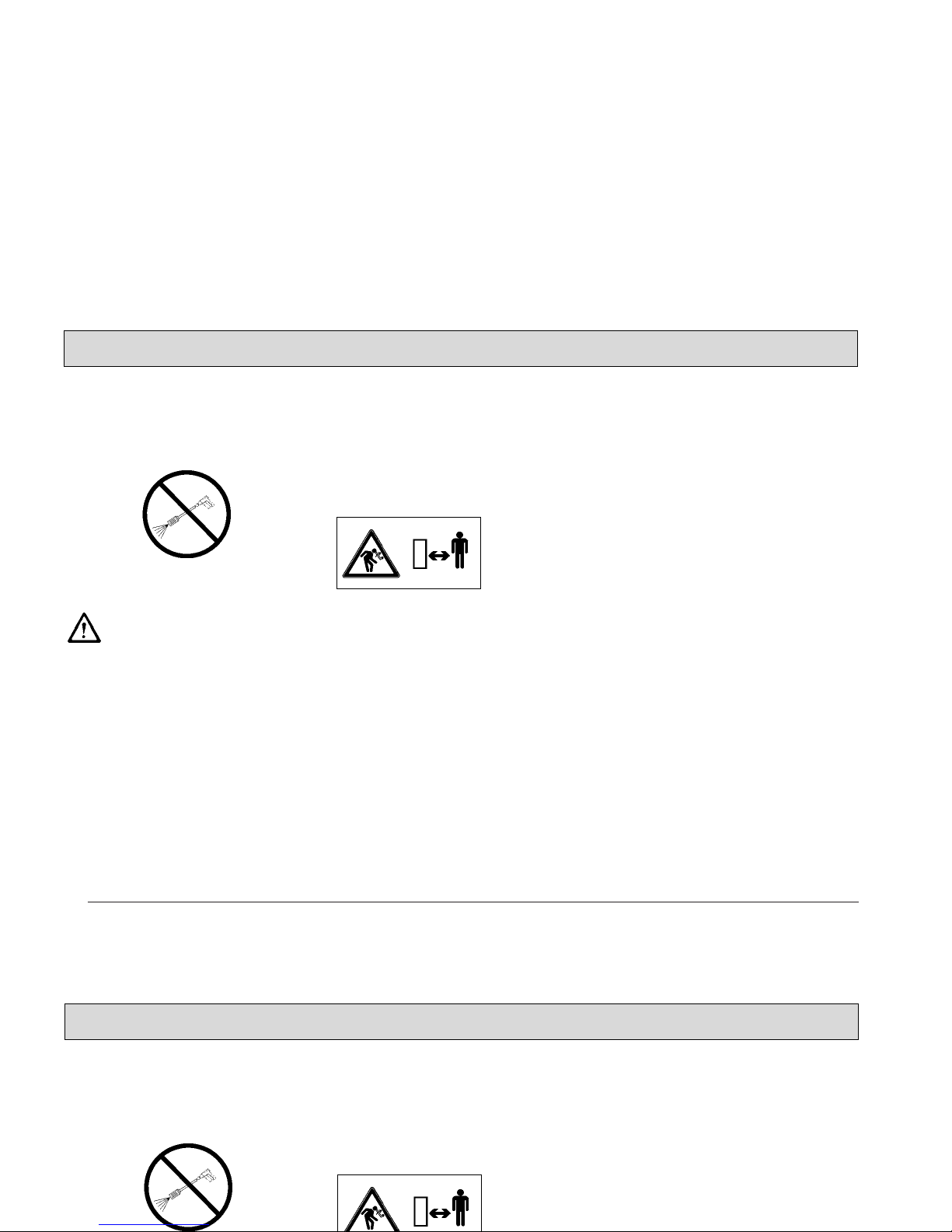
Pinching and shearing hazard. Provide for required
safe distance before lifting
or lowering the dirt hopper.
Shut down the engine before re-fuelling.
Smoking and handling open
flames is prohibited when
filling fuel tanks or when
working at or in the vicinity
of components containing
fuel.
Safety Information
1 1 Safety Information
1.1 General Safety Information
Apart from the instructions contained
in this manual, the general safety
instructions and accident prevention
regulations, as imposed by law will
have to be complied with. Do not put
the Manual aside without reading it
Keep clear of hazard zone!
Before commencing work, the operator has to make sure that the Apex 49
and its accessories are in proper and
safe condition.
Warning and instruction labels attached to the machine contain important
information about safe operation.
Provide for sufficient
ventilation when sweeping
indoors (dust and
combustion gas).
Pinching and shearing hazard. Provide for required
safe distance before lifting
or lowering the dirt hopper.
Safety Information
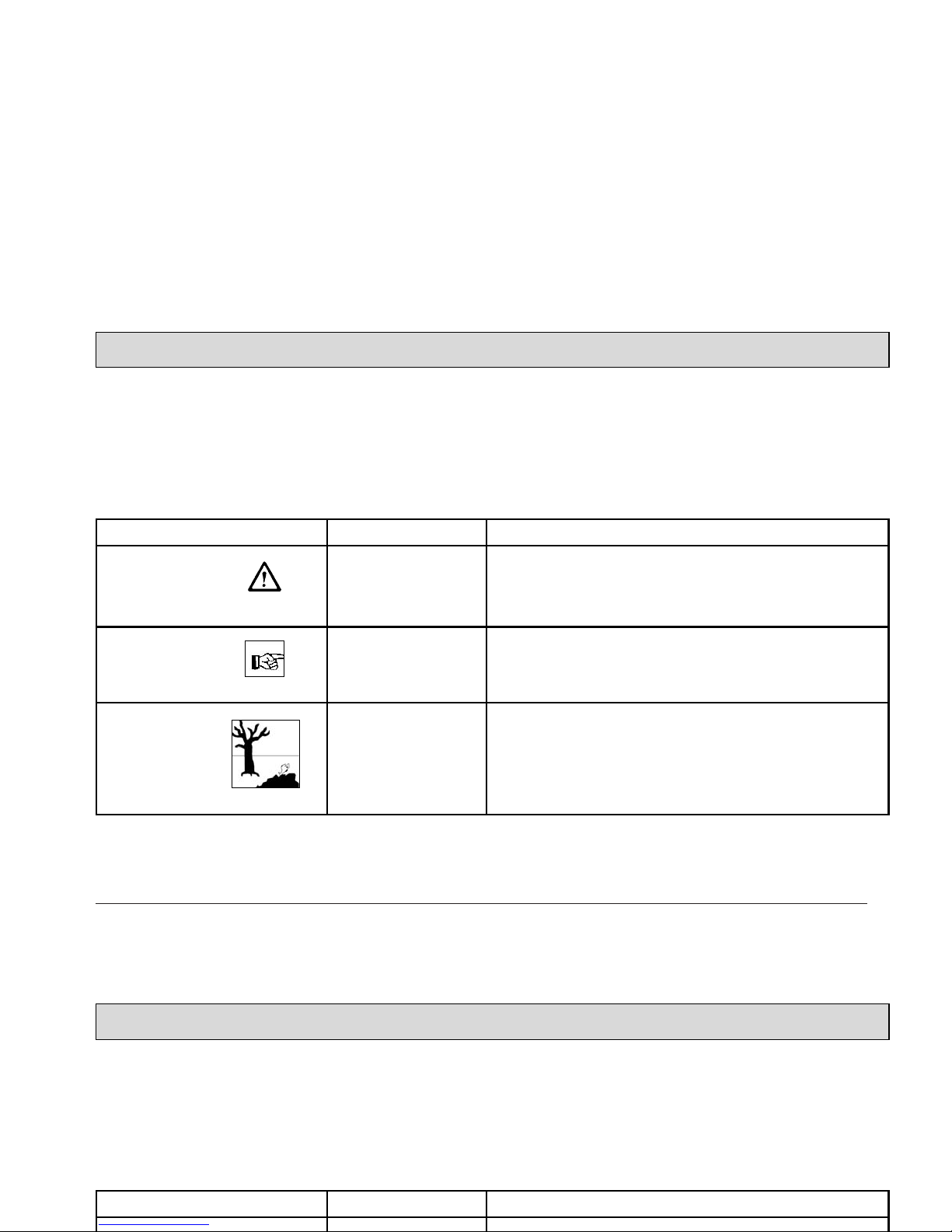
1.2 Safety and Warning Symbols
1.2.1 Generally Applicable Symbols
All paragraphs in this manual referring
to your personal safety, the safety of
your machine and the environment
protection are attributed one of the following warning symbols:
7
Safety Information
Hazardous for....
persons and
goods
the machine
the environment
Description
dangerous situation
caused by imprecise or non-observance of instructions or
prescribed work routine
important information on handling the Apex 47 in order to
maintain operability
due to use of substances representing an inherent danger to
health of environment
Symbol
DANGER
CAUTION
Ecological hazard
1.2 Safety and Warning Symbols
1.2.1 Generally Applicable Symbols
All paragraphs in this manual referring
to your personal safety, the safety of
your machine and the environment
protection are attributed one of the following warning symbols:
Safety Information
Hazardous for....
Description
Symbol
8
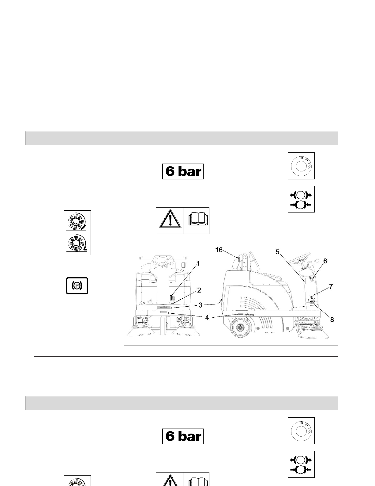
1.3 Labels at the Machine
The following safety and information
signs are legibly attached to the
machine. Missing or illegible stickers
have to be replaced.
Folding apron (1)
Parking brake (2)
Nameplate, front and rear (3)
Inflation pressure (4)
Read and observe operator's
Manual (5)
Ignition lock (6)
Brake (7)
Noise performance (8)
91 dB (A) Apex 47 G
91 dB (A) Apex 47 GH
Safety Information
Fig.1
1.3 Labels at the Machine
The following safety and information
signs are legibly attached to the
machine. Missing or illegible stickers
have to be replaced.
Folding apron (1)
Inflation pressure (4)
Read and observe operator's
Manual (5)
Ignition lock (6)
Brake (7)
Noise performance (8)
Safety Information

9
1.3 Labels at the Machine
Fig. 2 Safety and information signs
Hydraulic fluid (9)
Rotating parts (10)
Burning surface (11)
Cylinder broom wearing take-up (12)
Vehicle identification number (13)
Safety Information
1.3 Labels at the Machine
Hydraulic fluid (9)
Rotating parts (10)
Cylinder broom wearing take-up (12)
Safety Information
10
1.3 Labels at the Machine
High-pressure cleaner (14)
Do not clean by means of
high pressure cleaner or
vapour jet.
Apex 47 type name (15)
Pinching hazard (16)
(with the Apex GH only)
Safety Information
1.3 Labels at the Machine
High-pressure cleaner (14)
Safety Information
Apex 49 type name (15)
Pinching hazard (16)
(with the Apex GH only)
1.4 Operation/Safety
Information
Vacuum sweepers may be run by qualified personnel only; such personnel
will have to have evidenced their qualification for running the machine to
the owner or his authorised representative; operators explicitly will have to
be instructed by the owner or his
authorized representative to use the
machine.
The machine may be used
for cleaning such surfaces
approved by the owner or
this authorised representative for operation of vacuum sweepers.
Before starting the engine,
switch off all drives
Transporting persons on the machine
is prohibited. Ride-on machine types
are to be started with the driver being
seated.
Never leave the machine unattended
before the motors are off and the machine is protected against unintended
movements.
To prevent the machine from unauthorised use, pull the control key to block
all drives.
Shut down the motors before transport
of the machine. The driver has to take
account of local conditions and when
operating the sweeper he has to watch
out for other persons, especially children.
Do not open hood or
fairings with the machine
running.
This machine must not be
used as dust-evacuating
machine with dust filter insert (separator) to collect
dusts which are hazardous
to health.
Compared to four-wheeled
vehicles, driving stability of
three-wheeled vehicles is
reduced. We thus recommend:
- do not negotiate curves at
high speed.
- do not turn at slopes but
on level ground only
- ride up- or downhill
straight.
11
Safety Information
1.4 Operation/Safety
Information
Vacuum sweepers may be run by qualified personnel only; such personnel
will have to have evidenced their qualification for running the machine to
the owner or his authorised representative; operators explicitly will have to
be instructed by the owner or his
Never leave the machine unattended
before the motors are off and the machine is protected against unintended
movements.
To prevent the machine from unauthorised use, pull the control key to block
all drives.
Shut down the motors before transport
of the machine. The driver has to take
account of local conditions and when
operating the sweeper he has to watch
Compared to four-wheeled
vehicles, driving stability of
three-wheeled vehicles is
reduced. We thus recommend:
- do not negotiate curves at
high speed.
- do not turn at slopes but
on level ground only
- ride up- or downhill
Safety Information
12
Warning and instruction labels attached to the machine contain important information about safe operation
Provide for sufficient ventilation when sweeping indoors (dust and combustion
gas).
Proceed to filter shaking only if the dirt hopper is in closed position.
1.5 Cleaning Information
The machine is splash-proof (IPX3).
Do not clean the Apex 47 by
means of high pressure cleaner or vapour jet.
Proceed to cleaning of the
dirt hopper in regular intervals to preclude formation
of bacterial deposits.
Safety Information
Warning and instruction labels attached to the machine contain important information about safe operation
Provide for sufficient ventilation when sweeping indoors (dust and combustion
gas).
1.5 Cleaning Information
The machine is splash-proof (IPX3).
Do not clean the Apex 49 by
means of high pressure cleaner or vapour jet.
Safety Information
1.6 Maintenance Instructions
A good approach to prevention of accidents is proper maintenance of the
machine.
Before proceeding to repair or maintenance work pull the key.
Use appropriate tools for maintenance, service, setting etc.
As far as aspects of safety are concerned, spare parts will have to be at
least of the same quality as the genuine spare parts.
Switch off the motors before maintaining the machine
or replacing parts of it. Turn
off the machine and pull the
key.
Check hydraulic hoses and
lines for leakage or damages in regular intervals. Replace defective hoses and
lines immediately.
Before changing wheels
protect the machine against
rolling by placing wedges.
Proceed to wheel changing
when the machine is on level and solid ground.
Do not repair the pneumatic
tires mounted to the machine yourself. Dismount the
wheel and take it to repair to
a tire workshop.
Use of other than the cylinder brooms and side brushes approved by the manufacturer is not admitted (see
technical data) since use of
other cylinder brooms and
side brushes may affect
your safety.
When handling lubricating agents, the applicable regulations for
protection of the environment and prevention of fire have to be
complied with. Provide
for disposal of used oil
and grease in accordance with the provisions imposed by law.
Collect cleaning
agents, oil, fuel oil,
grease etc. and provide for adequate disposal. Wipe away spilled
substances.
13
Safety Information
1.6 Maintenance Instructions
A good approach to prevention of accidents is proper maintenance of the
machine.
Before proceeding to repair or maintenance work pull the key.
Use appropriate tools for maintenance, service, setting etc.
As far as aspects of safety are concer-
Before changing wheels
protect the machine against
rolling by placing wedges.
Proceed to wheel changing
when the machine is on level and solid ground.
Do not repair the pneumatic
tires mounted to the machine yourself. Dismount the
When handling lubricating agents, the applicable regulations for
protection of the environment and prevention of fire have to be
complied with. Provide
for disposal of used oil
and grease in accordance with the provisions imposed by law.
Safety Information
14
Before commencing any
work on the electric system
disconnect battery (neg. lead) of the Apex 47 and pull
the ignition key.
Do not keep batteries discharged for a longer period; always recharge them
as soon as possible.
Top with distilled water only.
Never refill battery acid in
battery cells of perfect condition.
Keep batteries dry and clean and clear of soiling such
as e.g. metallic dust to avoid leakage current.
Do not place metal objects
or tools onto batteries.
Short-circuit and deflagration hazard.
Spilled (straight) battery
acid must not get into the
sewage system before having been neutralised. Comply with the regulations imposed by law and observe
local provisions.
Battery acid is highly
caustic (keep clear of
children).
When checking the battery
acid level, wear safety glasses. If acid splashes get into the eyes rinse with clear
water for 15 minutes and
contact a doctor imm
ediately.
Use appropriate protective
means (e.g. protective gloves or finger-stalls) when
handling battery acid.
Do not use open flames
(explosion hazard).
Safety Information
Before commencing any
work on the electric system
disconnect battery (neg. lead) of the Apex 49 and pull
the ignition key.
Do not keep batteries discharged for a longer period; always recharge them
as soon as possible.
Keep batteries dry and clean and clear of soiling such
as e.g. metallic dust to avoid leakage current.
Do not place metal objects
or tools onto batteries.
Short-circuit and deflagration hazard.
Battery acid is highly
caustic (keep clear of
children).
When checking the battery
acid level, wear safety glasses. If acid splashes get into the eyes rinse with clear
water for 15 minutes and
contact a doctor imm
ediately.
Use appropriate protective
Safety Information

15
Safety Information
1.7 Accident Prevention Regulations
BGV D 29 Vehicles
According to BGV D 29, the Apex 47 sweeper has to be inspected for safe
condition by an authorized expert as required, but not less than once a year .
Results of such an inspection have to be kept on file at least until the next
inspection is performed.
BGV D 27 Industrial trucks
Observe as well: - the applicable provisions for Safety and Health at W ork and the Fire Regulations
- internal safety provisions
Safety Information
1.7 Accident Prevention Regulations
BGV D 29 Vehicles
According to BGV D 29, the Apex 49 sweeper has to be inspected for safe
condition by an authorized expert as required, but not less than once a year .
Results of such an inspection have to be kept on file at least until the next
inspection is performed.
BGV D 27 Industrial trucks
Observe as well: - the applicable provisions for Safety and Health at W ork and the Fire Regulations
16
2 Description
2.1 Functional Description
2.1.1 Apex 47 G
Principle of
Apex 47 G
The side brush is used to collect dirt at
borders and to enlarge the working
width as well as to increase the area
performance on large surfaces.
The cylinder broom casts the debris
overhead into the dirt hopper. The collected fine dust is evacuated by the
suction fan and separated by a filter
system. The air returned into the environment is clean.
Dirt disposal at the Apex 47 G is realized via two dirt hoppers (2x30 litres)
which are to be emptied manually.
Dirt disposal at the Apex 47 GH is realized via lift-up disposal (lift-up height >
1350mm) directly into standard waste
containers.
2.1.2 Apex 47 GH
Principle of
Apex 47 GH
Description
Fig.3
Fig.4
2 Description
2.1 Functional Description
2.1.1 Apex 49 G
The side brush is used to collect dirt at
borders and to enlarge the working
width as well as to increase the area
performance on large surfaces.
The cylinder broom casts the debris
overhead into the dirt hopper. The collected fine dust is evacuated by the
suction fan and separated by a filter
system. The air returned into the environment is clean.
Dirt disposal at the Apex 49 G is reali-
2.1.2 Apex 49 GH
Description

17
2.2 Cylinder Broom
The cylinder broom is equipped with
12 rows of bristles arranged in
V-shape.
The cylinder broom width amounts to
700mm and its diameter to 345mm.
2.3 Side Brush
The standard version, the side brush is
located at the front right of the machine. The operator lifts and lowers it by
hand lever.
The side brush is to have a light inclination.
The swinging area of the side brush
arm is limited by stop screws.
The side brush is driven by V-belt.
For special application, fitting of a
second side brush at the left is possible.
2.4 Filter System / Dust
Evacuation
The filter system is located in the filter
case above the dirt hopper. The suction fan transports the fine dust raised
by the cylinder broom to the plate filter
where it is separated. The fine dusts
sets at the outsides of the filter blades.
In case of heavy dust deve-
lopment, check and clean
the plate filter at regular
intervals.
2.5 Shaking System
Due to normal working vibration the
set dust partly falls off into the dirt
hoper. To ensure working in a dustfree ambiance, however, actuate the
shaking system regularly, or after
request by the pilot lamp at the latest.
2.6 Steering
Steerage is effectuated mechanically
from steering wheel to front wheel via
chain. This chain is to be re-adjusted
as required.
2.7 Wheels
2.7.1 Apex 47 G
Front wheel: pneumatic tire 4.00-4
Rear wheels: pneumatic tire 4.00-4
2.7.2 Apex 47 GH
Front wheel: pneumatic tire 4.00-4
Rear wheels: pneumatic tire 4.00-4
Description
2.2 Cylinder Broom
The cylinder broom is equipped with
12 rows of bristles arranged in
V-shape.
The cylinder broom width amounts to
700mm and its diameter to 345mm.
2.3 Side Brush
2.4 Filter System / Dust
Evacuation
The filter system is located in the filter
case above the dirt hopper. The suction fan transports the fine dust raised
by the cylinder broom to the plate filter
where it is separated. The fine dusts
sets at the outsides of the filter blades.
2.6 Steering
Steerage is effectuated mechanically
from steering wheel to front wheel via
chain. This chain is to be re-adjusted
as required.
2.7 Wheels
2.7.1 Apex 49 G
Description

2.8 Brake
The Apex 47 is equipped with a service brake.
This brake has been constructed as
shoe brake and equally serves as parking brake.
It is located in the rear wheels and is
actuated via cables.
A special adjustment screw is situated
at the right-hand rear wheel.
Any work at the braking
system has to be executed
by qualified persons in a
qualified workshop only.
2.9 Travel Drive Assembly
The Apex 47 is equipped with a hydrostatic drive assembly which is driven
by the combustion engine via pump.
2.10 Hydraulic System
Lifted-Up Disposal
The hydraulic system comprises a
compact unit (hydraulic pump with
hydraulic tank), the hydraulic hoses
and a hydraulic cylinder.
Hydraulic fluid: Mobiloil DTE 15 M
The named hydraulic fluid has been
filled in the hydraulic system in the
factory.
Filling of hydraulic tank: 0.76 litre
18
Description
2.8 Brake
The Apex 49 is equipped with a service brake.
This brake has been constructed as
shoe brake and equally serves as parking brake.
It is located in the rear wheels and is
actuated via cables.
A special adjustment screw is situated
2.10 Hydraulic System
Lifted-Up Disposal
The hydraulic system comprises a
compact unit (hydraulic pump with
hydraulic tank), the hydraulic hoses
and a hydraulic cylinder.
Hydraulic fluid: Mobiloil DTE 15 M
Description
19
3 First Operation
The Apex 47 has been extensively
tested and submitted to a functional
check before delivery.
Only qualified personnel of your local
PowerBoss contact dealer are allowed
to proceed to first operation. After
shipping of the machine, we advise
your PowerBoss contact dealer. He will
contact you to make a date for briefing
lessons.
3.1 Apex 47
3.1.1 General
Smoking and handling open
flames is prohibited when
filling fuel tanks or when
working at or in the vicinity
of components containing
fuel.
Do not use the Apex 47 at
ambient temperatures of
more than 40°C.
Do not start the machine at
temperatures of -15°C or
less.
Liquid propellant gas
system: refer to LPG operating instructions.
3.1.2 Refill Fuel
The fuel tank is located under the foldable seat hood.
Use clean fuel oil only. Store
fuel in approved and closed
reservoirs only.
- Turn engine off
- Secure machine by engaging the
parking brake.
- Pull ignition key.
- Fold back seat hood.
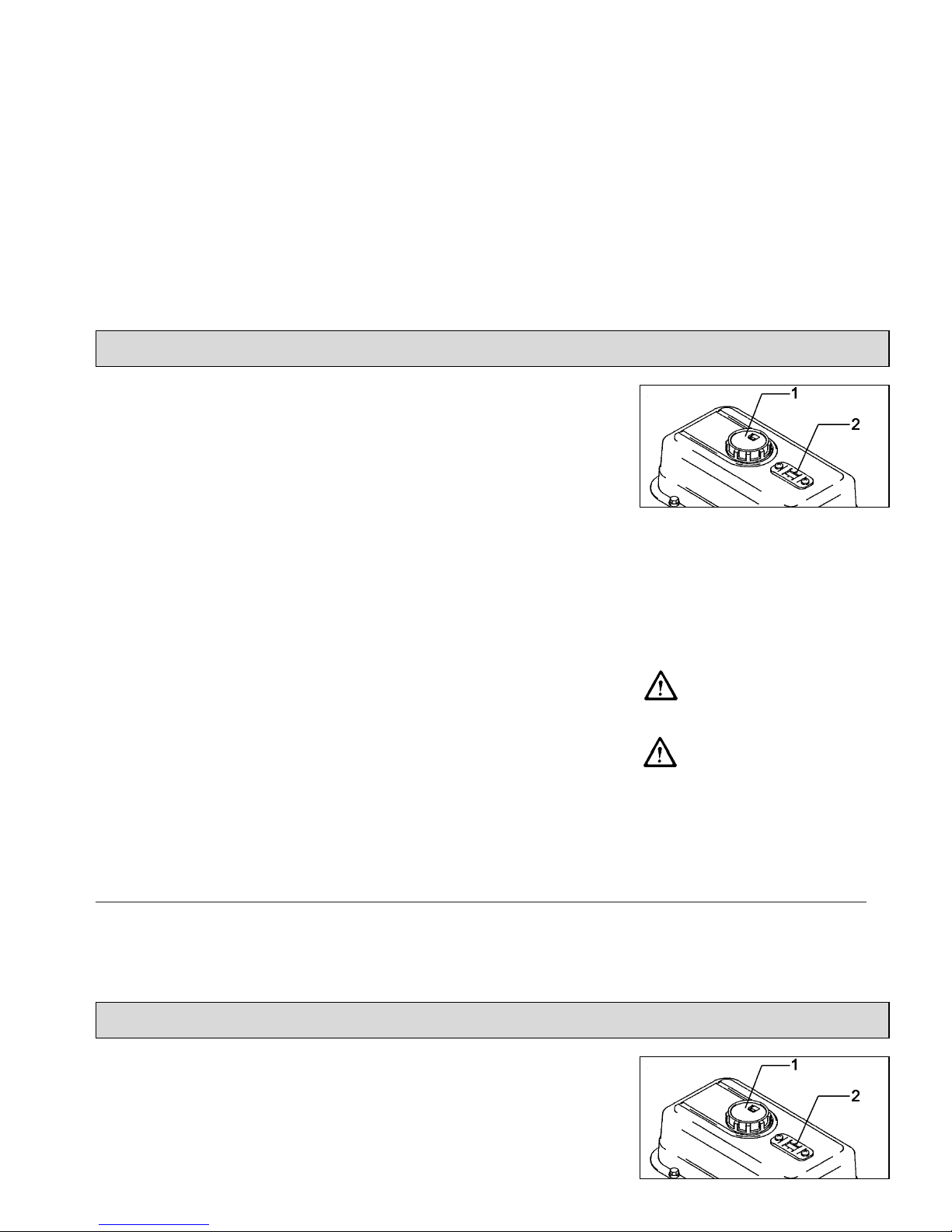
Fuel tank
- Check filling level at the filling level
indicator (Fig. 5/2).
- Remove tank lid (Fig. 5/1) before
filling.
Turn engine off before filling
fuel.
Smoking and handling open
flames is prohibited when
filling fuel tanks or when
working at or in the vicinity
of components containing
fuel.
First Operation
Fig.5
3 First Operation
The Apex 49 has been extensively
tested and submitted to a functional
check before delivery.
Only qualified personnel of your local
Minuteman contact dealer are allowed
to proceed to first operation. After
shipping of the machine, we advise
your Minuteman contact dealer. He will
Do not use the Apex 49 at
ambient temperatures of
more than 40°C.
Do not start the machine at
temperatures of -15°C or
less.
Liquid propellant gas
system: refer to LPG operating instructions.
Fuel tank
First Operation
Fig.5
3.1.3 Check Engine Oil Level
- Engine oil has been filled in the factory.
- For safety reasons, check the engine oil level (refer to paragraph 6.9.2,
Fig. 23/2)
- In order to protect the engine, it is
switched off or cannot be started if
engine oil level is insufficient.
This function is controlled by a low
oil level switch (Fig. 0/1) at the engine. A red pilot lamp (Fig. 0/2) is situated at this switch and lights simultaneously in case of insufficient oil
level.
Before the machine is operable again, refill oil until
the prescribed level is attained.
low oil level switch
Use clean oil only for
refilling.
Do not use used oil.
Store oil in approved and
closed reservoirs only.
20
First Operation
Fig.0
3.1.3 Check Engine Oil Level
- Engine oil has been filled in the factory.
- For safety reasons, check the engine oil level (refer to paragraph 6.9.2,
Fig. 23/2)
- In order to protect the engine, it is
switched off or cannot be started if
engine oil level is insufficient.
First Operation

21
4 Operation
4.1 Apex 47 Controls
1 Actuator for folding apron
2 Service brake lock
3 Service brake/parking brake pedal
4 Drive pedal, reverse
5 Drive pedal, forward
6 Control panel
7 Seat adjustment
8 Safety knob, lock for release of
swinging dirt hopper function (Apex
47 GH)
9 Release lever for swinging dirt
hopper function
(Apex 47 GH)
Operation
Fig.6
4 Operation
4.1 Apex 49 Controls
1 Actuator for folding apron
2 Service brake lock
3 Service brake/parking brake pedal
4 Drive pedal, reverse
5 Drive pedal, forward
6 Control panel
Operation

1 Actuator for folding apron
to open and close the folding apron
for collecting coarse dirt.
2 Service brake/parking brake lock
to lock the service brake/parking
brake. If locked, the service brake
works as parking brake. Release the
lock by depressing the service brake
pedal (3).
3 Service brake/parking brake pedal
to actuate the service brake at the
rear wheels. Before leaving the machine unattended, engage the service brake and lock.
4 Drive pedal, reverse
to change direction to reverse ride
with continuous regulation of riding
speed at the same time. If the driver
releases the pedal it returns to initial
position and the machine slows
down to standstill.
5 Drive pedal, forward
to change direction to forward ride
with continuous regulation of riding
speed at the same time. If the driver
releases the pedal it returns to initial
position and the machine slows
down to standstill.
6 Control panel
Refer to chapter "Control panel"
7 Seat adjustment
to adjust the seat position to drivers
of different height.
Adjust the seat so as to allow the
driver being comfortably seated and
attaining all elements required for
operation.
- Adjust seat lengthwise: push lever
slightly to the right and displace seat
forwards or backwards to the required position. Then let the lever catch
again.
8 Safety knob, lock for release of
swinging dirt hopper function
to release the lever for swinging dirt
hopper function.
9 Release lever for swinging dirt
hopper function
to swing the dirt hopper
22
Operation
1 Actuator for folding apron
to open and close the folding apron
for collecting coarse dirt.
2 Service brake/parking brake lock
to lock the service brake/parking
brake. If locked, the service brake
works as parking brake. Release the
lock by depressing the service brake
pedal (3).
4 Drive pedal, reverse
to change direction to reverse ride
with continuous regulation of riding
speed at the same time. If the driver
releases the pedal it returns to initial
position and the machine slows
down to standstill.
5 Drive pedal, forward
to change direction to forward ride
with continuous regulation of riding
- Adjust seat lengthwise: push lever
slightly to the right and displace seat
forwards or backwards to the required position. Then let the lever catch
again.
8 Safety knob, lock for release of
swinging dirt hopper function
to release the lever for swinging dirt
hopper function.
9 Release lever for swinging dirt
Operation

23
4.2 Apex 47 Control Panel
1 Cylinder broom lever
2 Release of lifted-up disposal func-
tion (Apex 47 GH)
3 Horn
4 Suction fan/shaking system knob
5 Choke flap knob
6 Flashlight (option)
7 Lighting (option)
8 Lift and lower lifted-up disposal unit
(Apex 47 GH)
9 Side brush lever
10 Pilot lamp, parking brake
11 Battery charge status indicator
12 Hourmeter
13 Pilot lamp, fan
14 Pilot lamp, shaking system
15 Engine speed regulation knob
16 Ignition switch
Operation
Fig.7
4.2 Apex 49 Control Panel
1 Cylinder broom lever
2 Release of lifted-up disposal func-
tion (Apex 49 GH)
3 Horn
4 Suction fan/shaking system knob
5 Choke flap knob
6 Flashlight (option)
7 Lighting (option)
8 Lift and lower lifted-up disposal unit
Operation

24
1 Cylinder broom lever
to lift and lower as well as to switch
on and off the cylinder broom and
the side brush.
- Lower cylinder broom as well as
switch on cylinder broom and side
brush
= push lever
- Lift cylinder broom as well as switch
off cylinder broom and side brush
= pull lever
2 Release for lifted-up disposal
function
to release the lifted-up disposal
function for lowering of lifting.
Has to be actuated before
pressing the key for
lifting/lowering lifted-up disposal function. Hold the key
during lifting/lowering.
Before changing lifting to lo-
wering or vice versa, the
"Release Lifted-Up Disposal" key has to be released
once and pressed again
3 Horn
An acoustic signal sounds upon
actuation of this button.
Operation
1 Cylinder broom lever
to lift and lower as well as to switch
on and off the cylinder broom and
the side brush.
2 Release for lifted-up disposal
function
to release the lifted-up disposal
function for lowering of lifting.
3 Horn
An acoustic signal sounds upon
actuation of this button.
Operation

If the engine has already at-
tained temperature, do not
actuate the choke flap and
start with full throttle.
6 Flashlight (option)
Operation
25
4 Suction fan/shaking system
knob
Knob position (from bottom to top):
Pos. 0 Activated vacuuming function
(close flap before sweeping
dry surfaces or collecting
dry dirt).
Pos. 1 Deactivated vacuuming
function (open flap before
sweeping wet surfaces and
collecting wet dirt).
Pos. 2 Shaking system ON (pull
knob to stop and then
release)
If the yellow pilot lamp (Fig. 7/13)
lights, actuate the shaking system (position 2).
In this position, the shaking system is
operable and proceeds to jolting in 7
repeated intervals.
After jolting, the knob is to
be kept in position 1 for about 10 seconds.
Reduce engine speed to idling in order to optimize the
cleaning result in case of
heavy fine dust load or stop
the engine.
5 Choke flap knob
to actuate the choke
flap (cold start).
- Knob down - choke not actuated
- Knob pulled up - choke actuated
for cold start.
If the engine has already at-
tained temperature, do not
actuate the choke flap and
start with full throttle.
6 Flashlight (option)
to switch the flashlight ON/OFF.
7 Lighting (option)
to switch the driving headlight
ON/OFF.
Operation
If the yellow pilot lamp (Fig. 7/13)
lights, actuate the shaking system (position 2).
In this position, the shaking system is
operable and proceeds to jolting in 7
repeated intervals.
After jolting, the knob is to
be kept in position 1 for about 10 seconds.
Reduce engine speed to id-

26
8 Lift and lower (lifted-up disposal)
to lift and lower the dirt hopper.
Lift the dirt hopper by pressing the
key until the desired height for lifting-out is attained.
When lowering the dirt hopper make sure to hold the key pressed until the hopper has contact with the
frame.
Actuate release key for lifted-up disposal and hold
before lifting or lowering.
9 Side brush lever
to lift and lower the side brush.
- Lower side brush
= push lever
- Lift side brush
= pull lever
10 Pilot lamp, parking brake (red)
lights upon actuation of the parking
brake Extinguishes upon release of
the parking brake.
11 Battery charge status indicator
(red)
lights upon actuation of the ignition
switch and has to extinguish as the
engine fires.
12 Hourmeter
indicates the operating hours. The
counter works only if the driver is
seated and the ignition is ON.
Operation
8 Lift and lower (lifted-up disposal)
to lift and lower the dirt hopper.
Lift the dirt hopper by pressing the
key until the desired height for lifting-out is attained.
When lowering the dirt hopper ma-
9 Side brush lever
to lift and lower the side brush.
- Lower side brush
= push lever
11 Battery charge status indicator
(red)
lights upon actuation of the ignition
switch and has to extinguish as the
engine fires.
Operation

27
13 Pilot lamp, suction fan (orange)
lights if the suction fan is not activated.
14 Pilot lamp, shaking system (yel-
low)
Proceed to jolting of the filter
system upon lighting of this pilot
lamp by actuating the knob
(Fig.7/5).
The pilot lamp flashes during the shaking procedure
and extinguishes after filter
has been cleaned. Jolting is
effectuated in 7 intervals.
15 Engine speed regulation knob
to adjust the engine speed. Service
speed is attained by pulling the
knob up.
16 Ignition switch
to switch ignition on and off, to start
and stop engine and to secure it
against unauthorised use.
For safety reasons, the Apex
47 has been equipped with
a seat contact switch.
Starting the engine is possible only after the driver has
taken place on the seat. If
seat contact is interrupted
while the engine is running,
the combustion engine of
the Apex 47 has to be restarted.
Operation
13 Pilot lamp, suction fan (orange)
lights if the suction fan is not activated.
15 Engine speed regulation knob
to adjust the engine speed. Service
speed is attained by pulling the
knob up.
For safety reasons, the Apex
49 has been equipped with
a seat contact switch.
Starting the engine is possible only after the driver has
taken place on the seat. If
seat contact is interrupted
while the engine is running,
the combustion engine of
the Apex 49 has to be restarted.
Operation

28
4.3 Empty Dirt Hoppers of Apex
47 G
- Fold bow (Fig. 8/3) up
= the dirt hoppers (Fig. 8/2) are lowe-
red.
- Use the recessed grip (Fig. 8/1) of
one of the hoppers to lift it lightly
and extract it.
- Take the hopper at its bow-type
handle to disposal and empty.
- Empty second dirt hopper as descri-
bed above.
- Re-insert dirt hopper (Fig. 8/2) and
fold down the bow (Fig. 8/3).
Emptying dirt hopper
1 Recessed grip in dirt hopper
2 Dirt hopper
3 Bow to lift/lower dirt hoppers
Clean dirt hoppers at
regular intervals.
4.4 Empty Dirt Hopper of
Apex 47 GH
Lift side brush and cylinder
broom before emptying of
the dirt hoppers.
If the hopper is lifted with
the cylinder broom still running, the engine is switched
off.
Emptying dirt hopper
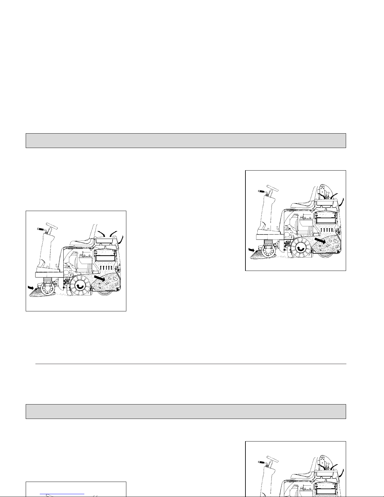
1 Lift-out arm
2 Lift-out cylinder
3 Dirt hopper
4 Bow-type handle
Clean dirt hopper at regular
intervals.
Operation
Fig.8
Fig.9
4.3 Empty Dirt Hoppers of Apex
49 G
- Fold bow (Fig. 8/3) up
= the dirt hoppers (Fig. 8/2) are lowe-
red.
- Use the recessed grip (Fig. 8/1) of
one of the hoppers to lift it lightly
and extract it.
- Take the hopper at its bow-type
handle to disposal and empty.
1 Recessed grip in dirt hopper
2 Dirt hopper
3 Bow to lift/lower dirt hoppers
Clean dirt hoppers at
regular intervals.
4.4 Empty Dirt Hopper of
Operation

29
Riding with the lifted hopper
reduces stability of the machine significantly. For this
reason, do not lift the hopper but just before emptying. Before lifting the hopper, the operator has to
make sure that no persons
or objects are behind or
next to the machine. Stop
the machine on level
ground before lifting the
hopper.
When the hopper is lifted,
the operator has to ride the
machine slowly.
Keep clear of the hazard
zone!
Pinching and shearing hazard. Provide for required
safe distance before lifting
or lowering the dirt hopper.
Apex 47 GH control panel
1 Release switch for lifted-up disposal
function
2 Dirt hopper, lift and lower
Proceed to emptying of the dirt
hopper as follows:
- Lift and switch off side brush and
cylinder broom
- Proceed to shaking of the filter
system
- Actuate switch (Fig. 10/1) and hold
(dirt hopper is released)
- Actuate switch (Fig. 10/2) by
pushing = lift dirt hopper
- Dirt hopper (Fig. 9/3) is lifted-out
- Back the Apex 47 GH until the dirt
hopper is positioned above the
container for disposal.
- Pull the safety knob (Fig. 11/1) of
the release lever (Fig. 11/2).
- Release swinging of the dirt hopper
by release lever (Fig. 11/2).
- Forward the Apex 47 GH after
emptying.
Operation
Fig.10
Riding with the lifted hopper
reduces stability of the machine significantly. For this
reason, do not lift the hopper but just before emptying. Before lifting the hopper, the operator has to
make sure that no persons
or objects are behind or
next to the machine. Stop
the machine on level
Pinching and shearing hazard. Provide for required
safe distance before lifting
or lowering the dirt hopper.
Proceed to emptying of the dirt
hopper as follows:
- Lift and switch off side brush and
cylinder broom
- Proceed to shaking of the filter
system
- Actuate switch (Fig. 10/1) and hold
(dirt hopper is released)
- Actuate switch (Fig. 10/2) by
pushing = lift dirt hopper
Operation

- Lower dirt hopper by actuating switch
(Fig. 10/1) and switch (Fig. 10/2);
pull lever = lower dirt hopper
Observe the information gi-
ven in paragraph 4.2/2 on
releasing of lifted-up disposal.
If the hopper is lifted, the
sweeping function is blokked. If the main broom is lowered even if the hopper is
lifted, the combustion engine stops. Starting is then
possible only after sweeping function is turned off
(main broom lever in OFF
position) or the hopper is
lowered. (Under condition
that the driver is seated)
Lifted-up disposal function
is blocked as long as sweeping function is ON.
Release lever, swing dirt hopper
1 Safety knob
2 Release lever, swing dirt hopper
If the cylinder broom is swit-
ched on with the dirt hopper
being lifted, the engine
stops.
Should the dirt hopper not
be completely emptied after
swinging, proceed to manual shaking with the handle
(Fig. 9/4).
Clean the dirt hopper in re-
gular intervals.
The dirt hopper is approved
only for a max. filling of 70
litres but not more than a
weight of 110kg.
30
Operation
Fig.11
- Lower dirt hopper by actuating switch
(Fig. 10/1) and switch (Fig. 10/2);
pull lever = lower dirt hopper
Observe the information gi-
ven in paragraph 4.2/2 on
releasing of lifted-up disposal.
If the cylinder broom is swit-
ched on with the dirt hopper
being lifted, the engine
stops.
Should the dirt hopper not
be completely emptied after
swinging, proceed to manu-
Operation

31
4.5 Working with the Apex 47
The driver is requested to carefully
read this manual. All controls are marked with easy-to-understand symbols
that ease familiarization. First driving
attempts should be limited to clear
areas until you are familiar with all
controls and their functions.
Please comply with the following safety provisions:
When working with the
Apex 47 all safety measures
generally applicable for
handling vehicles have to
be observed. No passenger
transport is admitted with
the Apex 47. Warning and
instruction labels attached
to the machine contain important information about
safe operation and guarantee your personal safety.
Before commencing work,
the operator has to make
sure that the machine and
its accessories are in proper
and safe condition and
comply with the provision
for safety at work. Do not
operate the Apex 47 without
protective devices.
4.5.1 Before Start of Engine
Open seat hood and check the following:
- Engine oil level
- Visual check of the V-belts
- Fuel filling
- Open fuel cock (is located at a slot
of the air cleaner)
- Close seat hood
4.5.2 Start Engine
For safety reasons, the Apex 47 is
equipped with a seat contact switch.
Starting the engine is possible only
when the driver is seated.
- Switch all levers and switches to
neutral position. Actuate parking
brake.
- Actuate choke (with cold engine
only)
- Turn ignition key to switch on
ignition
- Continue turning ignition key clokkwise to start engine.
If the starting procedure has
to be repeated or if the engine stops, re-starting is possible only after ignition has
been turned off. The ignition
lock is equipped with a protection to preclude repeated
ignition with the engine running.
Operation
open
closed
4.5 Working with the Apex 49
The driver is requested to carefully
read this manual. All controls are marked with easy-to-understand symbols
that ease familiarization. First driving
attempts should be limited to clear
areas until you are familiar with all
controls and their functions.
comply with the provision
for safety at work. Do not
operate the Apex 49 without
protective devices.
4.5.1 Before Start of Engine
Open seat hood and check the follo-
4.5.2 Start Engine
For safety reasons, the Apex 49 is
equipped with a seat contact switch.
Starting the engine is possible only
when the driver is seated.
- Switch all levers and switches to
neutral position. Actuate parking
brake.
- Actuate choke (with cold engine
Operation

Interruption of the starting
procedure after 10 seconds
and brief pause between
starting cycles is recommended to save the battery.
- Let the engine run and then slowly
press the choke knob down.
4.5.3 Stop Engine
- Turn ignition key counter-clockwise.
4.5.4 Sweep
- Start engine
- Adjust service speed
In initial position, vacuuming is activated. If the collected dirt is wet, open the
flap.
- Lower cylinder broom and side
brush.
- Release parking brake.
- Slowly depress drive pedal until
desired speed has been attained.
- Regularly actuate shaking device to
clean filter.
- Check filling level of the dirt hopper
and empty if required.
Refer to LPG operating instructions for information
on how to start machine
equipped with liquid propellant gas system.
4.5.5 Stop and Park
- Release drive pedal which returns
automatically into its neutral position
and the machine slows down to
standstill.
- Actuate parking brake
- Lift side brush and cylinder broom
- Turn engine off
Slowing down the Apex 47 is
possible by applying opposite forces with the drive pedal or by using the service
brake.
When leaving the machine
unattended, pull key in order to preclude unauthorized use.
Close the fuel cock in case
of long-term standstill of the
machine.
32
Operation
Interruption of the starting
procedure after 10 seconds
and brief pause between
starting cycles is recommended to save the battery.
- Let the engine run and then slowly
press the choke knob down.
4.5.3 Stop Engine
- Lower cylinder broom and side
brush.
- Release parking brake.
- Slowly depress drive pedal until
desired speed has been attained.
- Regularly actuate shaking device to
clean filter.
- Check filling level of the dirt hopper
and empty if required.
Slowing down the Apex 49 is
possible by applying opposite forces with the drive pedal or by using the service
brake.
When leaving the machine
unattended, pull key in order to preclude unauthorized use.
Operation

33
4.5.6 Displace
If the Apex 47 should be moved with
the engine being off, actuate the
bypass valve (Fig. 12).
Before displacement of the
machine actuate the bypass
valve located at the drive
pump.
To do so, turn the lever (Fig. 13/1) of
the bypass valve anticlockwise
approx. a quarter turn against the
stop.
4.5.7 Transport
Before transporting the Apex 47 on
other vehicles, engage the parking
brake and secure the machine by
straps and by placing wedges at the
wheels.
Operation
Fig.13Fig.12
Fig.13
4.5.6 Displace
If the Apex 49 should be moved with
the engine being off, actuate the
bypass valve (Fig. 12).
Before displacement of the
machine actuate the bypass
valve located at the drive
pump.
Operation
Fig.13

34
Dimensions and weights
Length with side brush
Width without side brush
Width with 1 side brush
Width with 2 side brushes
Height above driver's seat
Max weight including accessories
Admissible total weight
Driving and sweeping performance
Forward speed
Reverse speed
Sweeping speed up to (4 km/h recommended)
Sweeping track w/o/with 1 side brush
with 2 side brushes
Theoretical sweep. perf. with 1 or 2 side brushes
without side brush
Gradability, max.
mm
mm
mm
mm
mm
kg
kg
km/h
km/h
km/h
mm
mm
m² / h
m² / h
%
1520
1000
1120
1240
1300
480
680
6,0
4,0
6,0
700/970
1240
5800/7450
4200
16
1520
1000
1120
1240
1300
410
580
6,0
4,0
6,0
700/970
1240
5800/7450
4200
16
Technical Data
Apex 47 Apex 47 G
Apex 47 GH
5 Technical Data
Dimensions and weights
Length with side brush
Width without side brush
Width with 1 side brush
Width with 2 side brushes
Height above driver's seat
Max weight including accessories
Admissible total weight
mm
mm
mm
mm
mm
kg
kg
1520
1000
1120
1240
1300
480
680
1520
1000
1120
1240
1300
410
580
Technical Data
Apex 49 Apex 49 G
Apex 49 GH
5 Technical Data

35
Filter system
Filtering surface
Plate filter
Cylinder broom
Length/diameter
Wearing limit
Speed
Sweeping track
Quantity of bristle rows
Serial bristling
Ground clearance of sealing
strips at broom compartment
Sealing strips, left, right, rear
Sealing strip, front
Side brushes
Diameter
Speed
Serial bristling
Dirt hopper
Hopper capacity
m²
piece
mm
mm
1/min
mm
mm
mm
1/min
liter
2,8
1
700 / 345
290
530 +/- 20
50 + 10
12 v-shaped
PA
1 / 1 / 4
460
90
PA
70
2,8
1
700 / 345
290
530 +/- 20
50 + 10
12 v-shaped
PA
1 / 1 / 4
460
90
PA
2x30
Technical Data
Apex 47 Apex 47 G
Apex 47 GH
on the ground
Filter system
Filtering surface
Plate filter
Cylinder broom
Length/diameter
Wearing limit
Speed
m²
piece
mm
mm
1/min
2,8
1
700 / 345
290
530 +/- 20
2,8
1
700 / 345
290
530 +/- 20
Technical Data
Apex 49 Apex 49 G
Apex 49 GH

36
Drive wheels
Pneumatic tyres with hose, size
Inflation pressure
Solid rubber tyres
Engine
Manufacturer
Type
Working process/no. of cylinders
Piston capacity
Performance at 3,600 rpm
Service speed (with cylinder broom, side brush and
suction fan being on)
Fuel tank capacity (regular, unleaded)
Fuel consumption
Engine oil / filling
Spark plug
Air cleaner insert (Kawasaki)
Pre-filter (Kawasaki)
bar
cm³
KW
1/min
liter
liter / h
Type/liter
4.00 - 4 6PR
6
Option
Kawasaki
FE 250 D
4- cycle / 1 cyl.
249
6
2475 +/- 25
5,3
1,2
15W-40 / 1,1
NGK BP 5 ES
11013-2128
11013-2129
4.00 - 4 6PR
6
Option
Kawasaki
FE 250 D
4- cycle / 1 cyl.
249
6
2475 +/- 25
5,3
1,2
15W-40 / 1,1
NGK BP 5 ES
11013-2128
11013-2129
Technical Data
Apex 47 Apex 47 G
Apex 47 GH
Drive wheels
Pneumatic tyres with hose, size
Inflation pressure
Solid rubber tyres
Engine
Manufacturer
Type
bar
4.00 - 4 6PR
6
Option
Kawasaki
FE 250 D
4.00 - 4 6PR
6
Option
Kawasaki
FE 250 D
Technical Data
Apex 49 Apex 49 G
Apex 49 GH

37
Hydraulic system Travel drive assembly
Hydraulic fluid, e.g. Mobiloil
Hydraulic tank, capacity
Fluid filter cartridge
Hydraulic system Lifted-up disposal unit
Compact unit (maintenance-free)
Hydraulic fluid, e.g. Mobiloil
Hydraulic tank, capacity
Electric system
Starter battery
Generator
liter
Bestell-Nr.
liter
V / Ah
A
DTE 15 M (or an
equivalent oil)
10
CS-050-P-10-A
DTE 15 M (or an
equivalent oil)
0,76
12 / 45
13
DTE 15 M (or an
equivalent oil)
10
CS-050-P-10-A
12 / 45
13
Technical Data
Apex 47 Apex 47 G
Apex 47 GH
Hydraulic system Travel drive assembly
Hydraulic fluid, e.g. Mobiloil
Hydraulic tank, capacity
Fluid filter cartridge
Hydraulic system Lifted-up disposal unit
liter
Bestell-Nr.
DTE 15 M (or an
equivalent oil)
10
CS-050-P-10-A
DTE 15 M (or an
equivalent oil)
10
CS-050-P-10-A
Technical Data
Apex 49 Apex 49 G
Apex 49 GH

38
Noise emission
The sound pressure level measured according to DIN EN
ISO 11201 and under standard operating conditions at the
operator's ear with
- operating status
fan, cylinder broom and side brush ON amounts to
The sound power level measured according to DIN EN ISO
3744 under standard operating conditions and maximum
volume flow amounts to
Vibrations
The frequency weighted acceleration measured according
to EN 1003 which have an effect upon the upper limbs
(hand-arm-system) amounts under normal working conditions
The frequency weighted acceleration measured according
to EN 1032 which have an effect upon the lower limbs (feet
and seat) amounts under normal working conditions
dB (A)
dB (A)
m/s
2
m/s
2
Technical Data
77
91
< 2,5
< 0,5
77
91
< 2,5
< 0,5
Apex 47 G
Apex 47 GH
Apex 47
Noise emission
The sound pressure level measured according to DIN EN
ISO 11201 and under standard operating conditions at the
operator's ear with
- operating status
fan, cylinder broom and side brush ON amounts to
The sound power level measured according to DIN EN ISO
3744 under standard operating conditions and maximum
volume flow amounts to
dB (A)
dB (A)
Technical Data
77
91
77
91
Apex 49 G
Apex 49 GH
Apex 49

39
6 Maintenance/Service
6.1 Maintenance Instructions
Compliance with our recommendations concerning maintenance work
will give you the certitude of having an
effective and dependable machine at
your disposal.
It is better to take precautions than
repairing damages - and it saves
money!
According to paragraph 57,
BGV D29, the Apex 47 vacuum sweeper has to be inspected for safe condition
by an authorized expert as
required, but not less than
once a year.
Results of such an inspection have to be kept on file
at least until the next inspection is performed.
Please contact your local PowerBoss
distributor if you cannot do the maintenance works as prescribed in the
maintenance schedule in-house. He
will have these works done for you
and has qualified personnel and genuine spare parts at disposal.
When cleaning or servicing
the machine, or replacing
parts, have the motors stopped and the key pulled, the
negative battery pole disconnected and the service
brake (parking brake) engaged.
In case of questions or orders for
spare parts, please always quote your
machine's serial indicated on the
nameplate
Refer to chapter 1.3.1 Fig. 2/13 for
position of nameplate.
Collect spilled oil and
provide for adequate
disposal.
Use appropriate tools for servicing,
maintenance and adjusting work only.
Spare parts at least will have to be of
the same quality as genuine parts are.
Do not remove or install tires or repair a rim. Take the
wheel and rim to a workshop where qualified personnel and the required specific tools are available.
When working at the electric system disconnect the
negative pole of the battery.
Maintenance/Service
6 Maintenance/Service
6.1 Maintenance Instructions
Compliance with our recommendations concerning maintenance work
will give you the certitude of having an
effective and dependable machine at
your disposal.
It is better to take precautions than
Please contact your local Minuteman
distributor if you cannot do the maintenance works as prescribed in the
maintenance schedule in-house. He
will have these works done for you
and has qualified personnel and genuine spare parts at disposal.
When cleaning or servicing
the machine, or replacing
Collect spilled oil and
provide for adequate
disposal.
Use appropriate tools for servicing,
maintenance and adjusting work only.
Spare parts at least will have to be of
the same quality as genuine parts are.
Maintenance/Service

40
6.2 Mount/Dismount Cylinder
Broom
The cylinder broom is accessible from
the left side of the machine and is to
be dismounted as follows:
- Lower cylinder broom
- Pull ignition key and protect by en-
gaging parking brake
- Remove cover
Remove cover
- Open locks (Fig. 14/2) by enclosed
square spanner (turn counter-clokkwise)
- Remove cover (Fig. 14/1)
Dismount cylinder broom
- Loosen star-shaped knob (Fig. 15/2)
and remove
- Remove cylinder broom seating
(Fig. 15/1)
- Turn handle (Fig. 15/3 +5) upwards
and unlock
- Remove plate with sealing strip (Fig.
15/4)
- Remove cylinder broom by pulling.
For mounting the cylinder broom proceed in inverse order.
6.3 Adjust Sweeping Track
An adjustment device allows adaptation to different sweeping conditions.
The cylinder broom has to be adjusted
for normal use and with regard to a
low degree of wearing as described in
the following.
Check the broom adjustment on level
ground as follows.
Maintenance/Service
Fig.14
Fig.15
6.2 Mount/Dismount Cylinder
Broom
The cylinder broom is accessible from
the left side of the machine and is to
be dismounted as follows:
- Lower cylinder broom
- Pull ignition key and protect by en-
gaging parking brake
- Remove cover
- Open locks (Fig. 14/2) by enclosed
square spanner (turn counter-clokkwise)
- Remove cover (Fig. 14/1)
- Turn handle (Fig. 15/3 +5) upwards
and unlock
- Remove plate with sealing strip (Fig.
15/4)
- Remove cylinder broom by pulling.
For mounting the cylinder broom proceed in inverse order.
Maintenance/Service

41
Before checking:
Mark level surface for checking broom adjustment by
chalk.
Check inflation pressure of
tyres (6bar).
- Secure machine by engaging parking brake.
- Lower cylinder broom and let it run
dry.
- Lift cylinder broom and forward the
Apex 47 a bit.
With the correct broom adjustment
the parallel sweeping marks have to
appear on the floor (sweeping
track).
The sweeping track width is to be
- 50mm with the Apex 47 G
- 50mm with the Apex 47 GH.
The sweeping track width can be
adjusted at the star-shaped knob (Fig.
16/2) as follows:
Broom adjustment
- Stop engine and pull key
- Engage parking brake
- Open seat hood
- Loosen handle (Fig. 16/3)
- Turn star-shaped knob (Fig. 16/1)
to the left = wider sweeping track
to the right = smaller sweeping track
- Fix handle (Fig. 16/3)
- Broom adjustment sticker (Fig. 16/2)
With one full turn of the
knob, the track widens or
broadens by approx. 10mm.
When exceeding the sweeping track width the cylinder broom wearing increases as well as the load of
the drive.
Fig. 17 Broom adjustment
sticker (in Fig. 16/2)
Maintenance/Service
Fig.16
Fig.17
Before checking:
Mark level surface for checking broom adjustment by
chalk.
Check inflation pressure of
tyres (6bar).
- Secure machine by engaging parking brake.
With one full turn of the
knob, the track widens or
broadens by approx. 10mm.
When exceeding the sweeping track width the cylinder broom wearing increases as well as the load of
the drive.
Maintenance/Service

42
6.4 Sealing Strips for Broom Compartment
In order to assure good function of the
sweeper, a perfect condition of the
sealing strips is required, especially in
order to attain the prescribed low pressure in the broom compartment, a
clean sweeping result and the less
possible wear of the sealing strips
(check the sealing strips of the broom
compartment for wearing and damages in regular intervals).
Replace defective sealing strips.
The ground clearance of the lateral
and rear sealing strips is adjustable
(oblong holes in the sealing strips).
Ground clearance sides:
approx. 1mm
rear:
approx. 4mm.
Proceed to adjustment with an inflation
pressure of the pneumatic tyres of
6bar.
Height of the front sealing strip (folding
apron) cannot be adjusted. Being
dragged, it has contact with the floor.
6.5 Folding Apron Adjustment
Adjust folding apron
- Turn engine off and pull key
- Secure machine by engaging parking brake
- Remove cover (as described in the
paragraph "Mount/Dismount Cylinder Broom").
- Remove bolt (Fig. 18/2).
- Modify adjustment by turning the fork
head (Fig. 18/1).
Modify adjustment such that
the cylinder broom does not
retract the sealing strip of
the folding apron during
operation.
Maintenance/Service
Fig.18
6.4 Sealing Strips for Broom Compartment
In order to assure good function of the
sweeper, a perfect condition of the
sealing strips is required, especially in
order to attain the prescribed low pressure in the broom compartment, a
clean sweeping result and the less
possible wear of the sealing strips
6.5 Folding Apron Adjustment
- Remove bolt (Fig. 18/2).
- Modify adjustment by turning the fork
head (Fig. 18/1).
Modify adjustment such that
the cylinder broom does not
retract the sealing strip of
the folding apron during
operation.
Maintenance/Service

43
6.6 Replace Side Brush
The side brush is located at the front
right of the machine (standard version). Use the lever (paragraph 4.2,
Fig. 7/9) to lift and lower the side
brush.
The side brush is to be lightly inclined
in forward and in outward direction.
The swinging area of the side brush
arm is limited by stop screws.
The side brush is driven by a V-belt.
Fitting of a second side brush for specific appliances is possible.
Proceed as follows for dismounting of
the side brush:
Replace side brush
- Turn engine off and pull key.
- Secure machine by engaging
parking brake
- Disconnect battery plug
- Side brush lifted
- Loosen hexagonal nut (Fig. 19/1)
und remove together with washer
- Remove screw (Fig. 19/2)
- Remove side brush
Proceed in inverse order for mounting
of the side brush.
Maintenance/Service
Fig.19
6.6 Replace Side Brush
The side brush is located at the front
right of the machine (standard version). Use the lever (paragraph 4.2,
Fig. 7/9) to lift and lower the side
brush.
The side brush is to be lightly inclined
in forward and in outward direction.
The swinging area of the side brush
Proceed in inverse order for mounting
of the side brush.
Maintenance/Service

44
6.7 Dismount Plate Filter
Proceed as follows for dismounting of
the plate filter:
- Turn engine off and pull key.
- Secure machine by engaging parking brake
- Open seat hood
- Open quick-release locks (Fig. 20/1)
- Remove cover, filter case (Fig. 20/2)
- Loosen wing screws (Fig. 21/2) and
remove.
- Fold back frame with electro-motor
(Fig. 21/3).
- Hook frame at indicated position
(Fig. 21/4)
- Remove plate filter (Fig. 21/5).
For mounting of plate filter proceed in
inverse order.
Dismount plate filter
1 Quick-release locks
2 Cover of filter case
3 Filter case
Maintenance/Service
Fig.20
6.7 Dismount Plate Filter
Proceed as follows for dismounting of
the plate filter:
- Turn engine off and pull key.
- Secure machine by engaging parking brake
- Open seat hood
- Open quick-release locks (Fig. 20/1)
- Remove cover, filter case (Fig. 20/2)
Maintenance/Service

Plate filter
1 Detent hook
2 Wing screws
3 Frame with electro-motor
4 Opening for detent lever
5 Plate filter
45
Maintenance/Service
Fig.21
Maintenance/Service

46
6.8 Basic Cleaning of Plate Filter
Hold the plate filter (Fig. 22/1) in vertical position and drop it from a height
of approx. 1 m to the even floor as
represented in Fig. 22.
The soiled side of the filter
points to the bottom.
Basic cleaning of plate filter
1 Plate filter
Maintenance/Service
Fig.22
Clearance approx. 1 m
Soiled side
Floor
6.8 Basic Cleaning of Plate Filter
Hold the plate filter (Fig. 22/1) in vertical position and drop it from a height
of approx. 1 m to the even floor as
represented in Fig. 22.
The soiled side of the filter
Maintenance/Service
Soiled side

47
6.9 Engine
6.9.1 General
The engine is a robust four-stroke
engine and easy-to-maintain.
Maintenance work is to execute at
regular intervals. Find the details described in the following.
Before cleaning or maintaining the machine as well as
before replacing parts, turn
the engine off and pull the
ignition key.
Use appropriate tools for
maintenance, service, setting etc.
As far as aspects of safety
are concerned, spare parts
will have to be at least of
the same quality as the genuine spare parts.
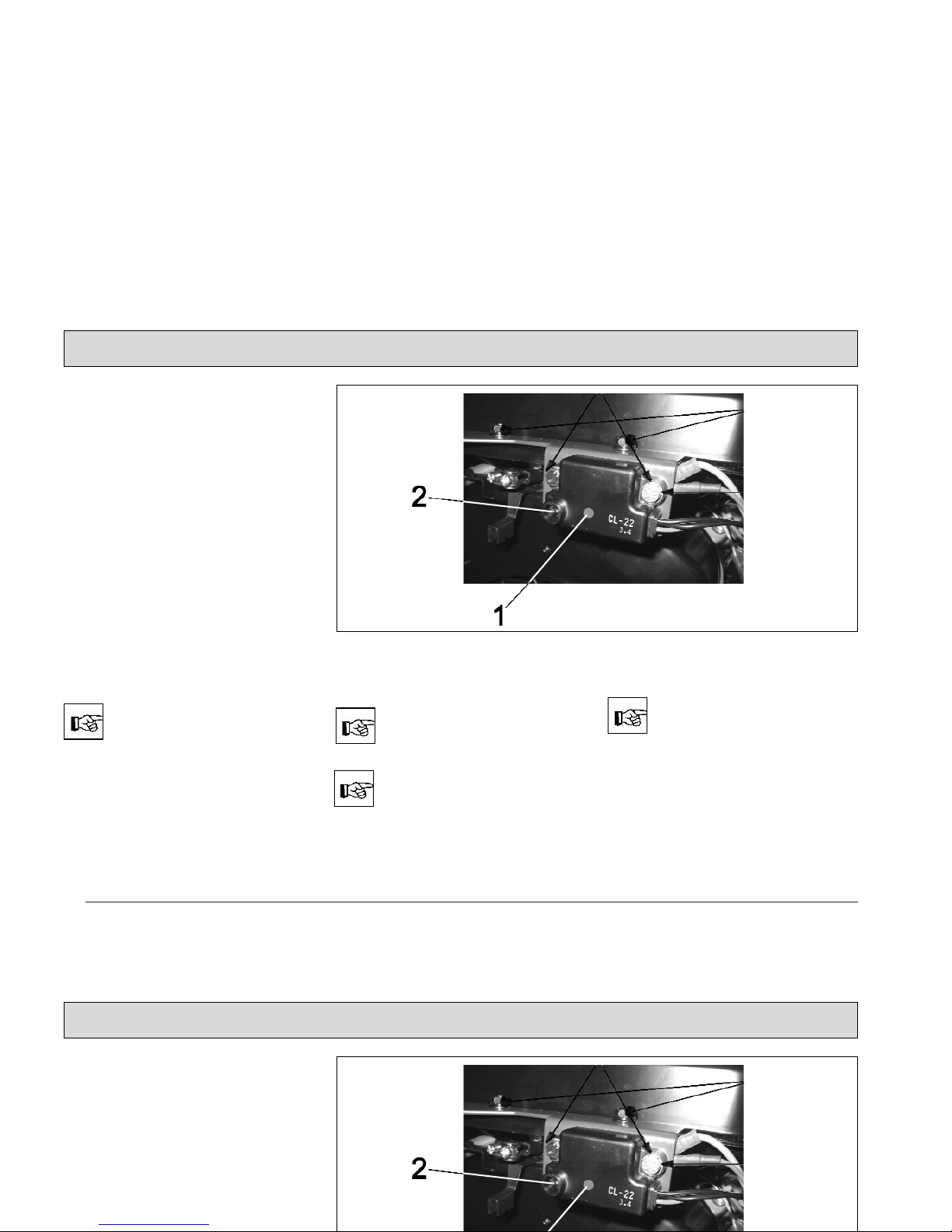
6.9.2 Check Engine Oil Level
Position the machine on level ground before checking
the engine oil level as follows:
Engine oil level check
If the machine has not been
used for a longer time, let
the engine run to have the
oil attained appropriate temperature.
- Turn engine off and pull key.
- Secure machine by engaging parking brake
- Open seat hood
- Pull plug (Fig. 23/1) with dipstick.
- Wipe dipstick, push it into opening
until stop and pull it again.
- Oil level has to mark between minimum and maximum, refill engine oil
if required.
- Re-insert plug.
The engine stops automatically in case of insufficient
oil level to preclude damages.
Maintenance/Service
Abb.23
6.9 Engine
6.9.1 General
The engine is a robust four-stroke
engine and easy-to-maintain.
Maintenance work is to execute at
regular intervals. Find the details described in the following.
6.9.2 Check Engine Oil Level
Position the machine on level ground before checking
the engine oil level as follows:
- Turn engine off and pull key.
- Secure machine by engaging parking brake
- Open seat hood
- Pull plug (Fig. 23/1) with dipstick.
- Wipe dipstick, push it into opening
until stop and pull it again.
- Oil level has to mark between minimum and maximum, refill engine oil
if required.
- Re-insert plug.
Maintenance/Service

6.9.3 Change Engine Oil
Engine oil changing, right side
of machine
Caution!
Burning hazard at muffler
pipe!
If the machine has not been
used for a longer time, let
the engine run to have the
oil attained appropriate temperature.
Proceed to the following befor
changing engine oil:
- Turn engine off and pull key.
- Secure machine by engaging parking brake.
- Open seat hood.
- Loosen quick-release locks (Fig.
20/1).
- Remove cover, filter case (Fig.
20/2).
- Loosen screws at the inside of the
right lateral fairing and remove.
- Lightly tilt lateral fairing to the outside then remove by pulling up.
- Remove drain hose (Fig. 24/1) from
holding clamp (Fig. 24/2) and lead it
downwards through the vehicle frame.
- Loosen clamp, pull drain plug from
the hose and drain oil.
- Close drain hose (Fig. 24/1) by plug
and protect with clamp.
- Fasten drain hose (Fig. 24/1) at holding clamp.
- Fill engine oil into check opening
with the machine standing on level
ground.
- Check oil level with dipstick, continue filling if required
Engine oil: SAE 15 W-40
Filling: approx. 1.1 litre
Use an oil-resistant funnel
for filling engine oil.
6.9.4 Air Cleaner
The air cleaner is located in the engine's compartment. Clean the foamtype filter after every 50 hours of operation and the paper insert after every
100 hours of operation.
Proceed to daily cleaning of
the air cleaner with heavy
dust formation.
48
Maintenance/Service
Fig.24
Direction of travel
6.9.3 Change Engine Oil
Proceed to the following befor
changing engine oil:
- Turn engine off and pull key.
- Secure machine by engaging parking brake.
- Open seat hood.
- Loosen quick-release locks (Fig.
20/1).
- Remove cover, filter case (Fig.
20/2).
- Fasten drain hose (Fig. 24/1) at holding clamp.
- Fill engine oil into check opening
with the machine standing on level
ground.
- Check oil level with dipstick, continue filling if required
Engine oil: SAE 15 W-40
Filling: approx. 1.1 litre
Maintenance/Service

49
Air cleaner
1 Air cleaner
2 Wing screw
3 Air cleaner cap with filtering insert
A soiled filtering insert may
lead to reduced performance and heavy smoking of
the engine. Never let the engine run without filtering insert.
Replace filtering insert as required.
Proceed as follows for dismounting the
filtering insert:
- Unscrew wing screw (Fig. 25/2) and
remove filter cap (Fig. 25/3) with
filtering insert.
- Remove foam-type filter and paper
filter (Fig. 26/3 and 4) and proceed
to dry cleaning or replace if required.
Air cleaner components
1 Wing screw
2 Air cleaner cap
3 Foam-type filter
4 Paper filter
6.10 Hydraulic System
The hydraulic units are oil- and maintenance-free. The hydraulic oil and filters are concerned by maintenance
work only.
Premature failure can be prevented by
regular inspection and periodical maintenance (see maintenance schedule
page 57 and following).
We recommend having all
other works at the hydraulic
system done by qualified
personal.
Maintenance/Service
Fig.25
Fig.26
Replace filtering insert as required.
Proceed as follows for dismounting the
filtering insert:
- Unscrew wing screw (Fig. 25/2) and
remove filter cap (Fig. 25/3) with
filtering insert.
- Remove foam-type filter and paper
filter (Fig. 26/3 and 4) and proceed
to dry cleaning or replace if requi-
6.10 Hydraulic System
The hydraulic units are oil- and maintenance-free. The hydraulic oil and filters are concerned by maintenance
work only.
Premature failure can be prevented by
regular inspection and periodical maintenance (see maintenance schedule
page 57 and following).
Maintenance/Service

6.10.1 Check Hydraulic Fluid Level
- Turn engine off and pull key.
- Secure machine by engaging parking brake.
- Open seat hood.
- Unscrew cap with dipstick
(Fig. 27/1)
- Wipe dipstick by means of cloth
- Screw cap until stop
- Unscrew cap with dipstick and
check hydraulic fluid level, refill if required
6.10.2 Refill Hydraulic Fluid
- Unscrew cap with dipstick and
check hydraulic fluid level according
to paragraph 6.10.1.
- Use appropriate oil-resistant recipient with mouth or funnel for refilling
- Proceed to check of fluid level after
refilling
Hydraulic fluid filter
1 Filler neck
2 Hydraulic oil filter
- Filling is sufficient if the bottom end
of the dipstick immerges into the fluid for approx. 5mm.
6.10.3 Change Hydraulic Fluid Filter
The hydraulic fluid filter is located in
the pump line and equipped with a
bypass valve in order to guarantee
fluid supply of the travel drive assembly even if the fluid filter is soiled.
Change the fluid filter after the first
100 hours of operation.
- Turn hydraulic fluid filter (Fig. 27/2)
counter-clockwise to loosen it and
unscrew
- Before screwing new filter, fill it
with oil
- Ride the machine a short distance
- Refill sufficient hydraulic fluid
- Check fluid filling level
Hydraulic fluid: Mobil DTE 15 M
or a fluid of similar quality.
50
Maintenance/Service
Fig.27
6.10.1 Check Hydraulic Fluid Level
- Turn engine off and pull key.
- Secure machine by engaging parking brake.
- Open seat hood.
- Unscrew cap with dipstick
(Fig. 27/1)
- Wipe dipstick by means of cloth
- Screw cap until stop
- Unscrew cap with dipstick and
6.10.3 Change Hydraulic Fluid Filter
The hydraulic fluid filter is located in
the pump line and equipped with a
bypass valve in order to guarantee
fluid supply of the travel drive assembly even if the fluid filter is soiled.
Change the fluid filter after the first
100 hours of operation.
Maintenance/Service

51
Should it be required to drain the
hydraulic fluid completely proceed as
follows:
- Turn engine off and pull key.
- Secure machine by engaging parking brake.
- Remove right-hand dirt hopper
(Apex 47 G only) or lift the dirt hopper of the Apex 47 GH, see paragraph 4.4.
- Place recipient under the drain plug
(drain plug is located underneath
the filter case at the right) and remove drain plug.
6.10.4 Check and Refill Hydraulic
System Lifted-Up Disposal
Hydraulic unit lifted-up disposal
Check hydraulic fluid level
- Turn engine off and pull key.
- Secure machine by engaging par-
king brake.
- Open seat hood
- Check hydraulic fluid level in tank
(Fig. 28/1). The hydraulic fluid level
must not fall below the minimum
(Fig. 28/2). It should read between
the minimum (Fig. 28/2) and the maximum (Fig. 28/3).
Refill hydraulic fluid
- Remove lid (Fig. 28/4) and refill as
required.
- Close lid of hydraulic fluid tank.
Use Mobiloil DTE 15 M fluid or a
hydraulic fluid of similar quality.
Dirt hopper has to be
lowered.
Maintenance/Service
Fig.28
Should it be required to drain the
hydraulic fluid completely proceed as
follows:
- Turn engine off and pull key.
- Secure machine by engaging parking brake.
- Remove right-hand dirt hopper
(Apex 49 G only) or lift the dirt hopper of the Apex 49 GH, see para-
6.10.4 Check and Refill Hydraulic
System Lifted-Up Disposal
- Check hydraulic fluid level in tank
(Fig. 28/1). The hydraulic fluid level
must not fall below the minimum
(Fig. 28/2). It should read between
the minimum (Fig. 28/2) and the maximum (Fig. 28/3).
Refill hydraulic fluid
- Remove lid (Fig. 28/4) and refill as
Maintenance/Service

6.11 V-Belt Drive
1 Suction fan V-belt (40Hz)
2 Tensioning roller
3 V-belt pulley
4 Hydraulic pump V-belt
5 Belt guide
6 Hexagonal nut
7 V-belt for cylinder broom and side
brush drive
8 Hydraulic pump belt pulley
9 Tensioning / coupling roller
10 Screws
11 Side brush V-belt
12 Belt pulley
13 Cylinder broom V-belt
14 Cylinder broom belt pulley
15 Tension spring
16 Tensioning roller lever
17 Tension spring
18 Tensioning roller lever for hydraulic
pump V-belt
19 Tensioning roller lever for cylinder
broom and side brush drive
V-belt drive
52
Maintenance/Service
Fig.29
6.11 V-Belt Drive
1 Suction fan V-belt (40Hz)
2 Tensioning roller
3 V-belt pulley
4 Hydraulic pump V-belt
5 Belt guide
6 Hexagonal nut
7 V-belt for cylinder broom and side
brush drive
8 Hydraulic pump belt pulley
Maintenance/Service

6.11.1 Replace Cylinder Broom V-Belt
- Turn engine off and pull key.
- Secure machine by engaging
parking brake.
- Remove bottom right fairing (turn
locks counter-clockwise by square
spanner).
- Detent tensioning spring (Fig. 29/15)
by left hand while taking the V-belt
off the tensioning roller with right
hand.
- Remove V-belt (Fig. 29/13).
Proceed in inverse order for mounting.
6.11.2 Replace Side Brush V-Belt
- Turn engine off and pull key.
- Secure machine by engaging parking brake
- Remove bottom right cover (turn
locks counter-clockwise by square
spanner).
- Remove cylinder broom V-belt (as
described in paragraph "Replace
Cylinder Broom V-Belt")
- Loosen screws (Fig. 29/10) at the
cover plate and remove
- Remove cover plate
- Push side brush from the front side
in direction of the machine to detent
V-belt (Fig. 29/11)
- Remove V-belt (Fig. 29/11)
Proceed in inverse order for mounting.
6.11.3 Replace Suction Fan V-Belt
- Turn engine off and pull key.
- Secure machine by engaging parking brake
- Open seat hood
- Loosen hexagon nuts (Fig. 29/6)
and remove together with belt guide
(Fig. 29/5)
- Detent V-belt (Fig. 29/7) with tensioning roller lever (Fig. 29/19) and take from the belt pulley
- Loosen tensioning roller (Fig. 29/2)
and detent the V-belt, and then remove.
.
Proceed in inverse order for mounting.
53
Maintenance/Service
6.11.1 Replace Cylinder Broom V-Belt
- Turn engine off and pull key.
- Secure machine by engaging
parking brake.
- Remove bottom right fairing (turn
locks counter-clockwise by square
spanner).
- Detent tensioning spring (Fig. 29/15)
by left hand while taking the V-belt
off the tensioning roller with right
6.11.2 Replace Side Brush V-Belt
- Turn engine off and pull key.
- Secure machine by engaging parking brake
- Remove bottom right cover (turn
locks counter-clockwise by square
spanner).
- Remove cylinder broom V-belt (as
described in paragraph "Replace
Cylinder Broom V-Belt")
6.11.3 Replace Suction Fan V-Belt
- Turn engine off and pull key.
- Secure machine by engaging parking brake
- Open seat hood
- Loosen hexagon nuts (Fig. 29/6)
and remove together with belt guide
(Fig. 29/5)
- Detent V-belt (Fig. 29/7) with tensioning roller lever (Fig. 29/19) and ta-
Maintenance/Service

54
6.11.4 Replace Hydraulic Pump V-Belt
- Turn engine off and pull key.
- Secure machine by engaging parking brake
- Open seat hood
- Loosen hexagon nuts (Fig. 29/6)
and remove together with belt guide
(Fig. 29/5)
- Detent V-belt (Fig. 29/7) with tensioning roller lever (Fig. 29/19) and take from the belt pulley
- Loosen tensioning roller (Fig. 29/2)
and detent the V-belt, and then remove.
- Unhinge tension spring (Fig. 29/17).
- Remove V-belt (Fig. 29/4).
Proceed in inverse order for mounting.
Maintenance/Service
6.11.4 Replace Hydraulic Pump V-Belt
- Turn engine off and pull key.
- Secure machine by engaging parking brake
- Open seat hood
- Loosen hexagon nuts (Fig. 29/6)
and remove together with belt guide
(Fig. 29/5)
- Detent V-belt (Fig. 29/7) with tensioning roller lever (Fig. 29/19) and ta-
Maintenance/Service

6.12 Electric System
1 F2 Pre-fuse (20A)
2 F3 Engine shutdown, hourmeter
(5A)
3 F4 Indicators control panel, jolter
controlling, (front right lighting
option, right rear light (5A)
4 F5 Horn (10A)
5 F7 LPG equipment option (10A)
6 F8 Front left lighting option,
left rear light (7.5A)
7 F9 Lifted-up disposal control
(7.5A)
8 F10 LPG equipment option (10A)
9 F11 Shaking motor (30A)
10 F12 Generator charge status
indicator (5A)
11 F14 Flashlight option (5A)
12 LPG option control unit
13 K6 Relay, lifted-up disposal
14 K7 Relay, lifted-up disposal
15 K8 Relay, lifted-up disposal
55
Maintenance/Service
Fig.30
6.12 Electric System
1 F2 Pre-fuse (20A)
2 F3 Engine shutdown, hourmeter
(5A)
3 F4 Indicators control panel, jolter
controlling, (front right lighting
option, right rear light (5A)
4 F5 Horn (10A)
5 F7 LPG equipment option (10A)
6 F8 Front left lighting option,
Maintenance/Service

Electric System, continued
16 K9 Relay, lifted-up disposal
17 K10 Relay, lift hopper
18 K11 Relay, lower hopper
19 K3 Relay
20 K4 Relay, filter monitoring
21 K5 Relay, impulse relay shaking
22 F13 Hydraulic unit for lifted-up
disposal (30A)
56
Maintenance/Service
Fig.30
Electric System, continued
16 K9 Relay, lifted-up disposal
17 K10 Relay, lift hopper
18 K11 Relay, lower hopper
19 K3 Relay
20 K4 Relay, filter monitoring
21 K5 Relay, impulse relay shaking
22 F13 Hydraulic unit for lifted-up
disposal (30A)
Maintenance/Service

Daily
after first
every 100 every 200 every 500
Check engine oil level and refill if required X
Check fuel level and refill if required (regular unleaded) X
Replace fuel filter (as required) X
Change engine oil (1.1 litre engine oil SAE 15-W-40) 5 X
Check engine air cleaner for soiling and clean if required (tap, do not use
compressed air), replace air cleaner insert if required
XX
Visual chec k of engine, pump and wheel motor for oil leakage X
Check idling and service speed (1,200rpm and 2475rpm) X
Check spark plug air gap (0.75mm) X
Replace spark plugs X
Check valve play (0.15mm inlet, 0.15mm outlet) each in cold s tate
X
Check starter battery acid level and top with distilled water if required, clean
and grease battery terminals
X
Change hydraulic fluid filter and refill fluid (use Mobiloil DTE 15 M or fluid of
equivalent quality)
100 X
Check cables and plugged connections for damages and tight fit
X
6.13 Maintenance Schedule
hours of operation
57
Maintenance/Service
Daily
after first
every 100 every 200 every 500
Check engine oil level and refill if required X
Check fuel level and refill if required (regular unleaded) X
Replace fuel filter (as required) X
Change engine oil (1.1 litre engine oil SAE 15-W-40) 5 X
Check engine air cleaner for soiling and clean if required (tap, do not use
6.13 Maintenance Schedule
hours of operation
Maintenance/Service

Daily
after first
every 100 every 200 every 500
Check function of seat contact switch X
Check exhaust s ystem X
Check inflation pressure (6bar) X
Check cylinder broom for wearing or foreign particles (e.g. wire, straps) and
replace broom if required
X
Check sweeping track and adjust if required X
Check sealing strips at the broom compartment, adjust if required or replace
defective sealing strips
X
Check sealing strips at dirt hopper, replace defective sealing strips X
Check side brush adjus tment and brush bristles for wearing, adjust if
required or replace side brush
X
Visual chec k of V-belts X
Check V-belt for wearing and correct tension and re-adjust if required 5 X
Check service/parking brake and re-adjust if required X
Check filter system for tightnes s X
Dismount plate filter and c lean if required
X
Check tread of wheels X
6.13 Maintenance Schedule
hours of operation
58
Maintenance/Service
Daily
after first
every 100 every 200 every 500
Check function of seat contact switch X
Check exhaust s ystem X
Check inflation pressure (6bar) X
Check cylinder broom for wearing or foreign particles (e.g. wire, straps) and
replace broom if required
X
6.13 Maintenance Schedule
hours of operation
Maintenance/Service

Daily
after first
every 100 every 200 every 500
Check hydraulic fluid level of lifted-up disposal function and refill if required X
Check tightening moment of fixing screws for lifted-up disposal and tighten if
required (49Nm)
5X
Check hydraulic hoses and replac e if required X
Check tension of steering chain and adjust tension if required X
6.13 Maintenance Schedule
hours of operation
59
Maintenance/Service
Daily
after first
every 100 every 200 every 500
Check hydraulic fluid level of lifted-up disposal function and refill if required X
Check tightening moment of fixing screws for lifted-up disposal and tighten if
required (49Nm)
5X
Check hydraulic hoses and replac e if required X
Check tension of steering chain and adjust tension if required X
6.13 Maintenance Schedule
hours of operation
Maintenance/Service

60
Maintenance Document
100 operating hours
Maintenance
Workshop stamp
carried out on __________
at __________ operating hours
200 operating hours
Maintenance
Workshop stamp
carried out on __________
at __________ operating hours
300 operating hours
Maintenance
Workshop stamp
carried out on __________
at __________ operating hours
400 operating hours
Maintenance
Workshop stamp
carried out on __________
at __________ operating hours
500 operating hours
Maintenance
Workshop stamp
carried out on __________
at __________ operating hours
600 operating hours
Maintenance
Workshop stamp
carried out on __________
at __________ operating hours
700 operating hours
Maintenance
Workshop stamp
carried out on __________
at __________ operating hours
800 operating hours
Maintenance
Workshop stamp
carried out on __________
at __________ operating hours
900 operating hours
Maintenance
Workshop stamp
carried out on __________
at __________ operating hours
1000 operating hours
Maintenance
Workshop stamp
carried out on __________
at __________ operating hours
1100 operating hours
Maintenance
Workshop stamp
carried out on __________
at __________ operating hours
1200 operating hours
Maintenance
Workshop stamp
carried out on __________
at __________ operating hours
Maintenance Document
100 operating hours
Maintenance
Workshop stamp
carried out on __________
at __________ operating hours
200 operating hours
Maintenance
Workshop stamp
carried out on __________
at __________ operating hours
300 operating hours
Maintenance
Workshop stamp
carried out on __________
at __________ operating hours
400 operating hours
Maintenance
Workshop stamp
carried out on __________
at __________ operating hours
500 operating hours
600 operating hours
700 operating hours
800 operating hours

PowerBoss Made Simple Commercial Limited Warranty
PowerBoss, Inc. warrants to the original purchaser/user that this product is free from defects in workmanship and materials under
normal use. PowerBoss will, at its option, repair or replace without charge, parts that fail under normal use and service when operated and
maintained in accordance with the applicable operation and instruction manuals.
All warranty claims must be submitted through and approved by factory authorized repair stations.
This warranty does not apply to normal wear, or to items whose life is dependent on their use and care, such as belts, cords,switches, hoses,
rubber parts, electrical motor components or adjustments. Parts not manufactured by are covered by and subject to the warranties and/or
guarantees of their manufacturers. Please contact PowerBoss for procedures in warranty claims against these manufacturers.
Special warning to purchaser -- Use of replacement filters and/or prefilters not manufactured by PowerBoss or its designated licensees, will void
all warranties expressed or implied.
A potential health hazard exists without original equipment replacement.
All warranted items become the sole property of PowerBoss or its original manufacturer, whichever the case may be. PowerBoss
disclaims any implied warranty, including the warranty of merchantability and the warranty of fitness for a particular purpose.
PowerBoss assumes no responsibility for any special, incidental orconsequential damages.
This limited warranty is applicable only in the U.S.A. and Canada, and is extended only to the original user/purchaser of this product. Customers
outside the U.S.A. and Canada should contact their local distributor for export warranty policies. PowerBoss is not responsible for costs or repairs
performed by persons other than those specifically authorized byPowerBoss. This warranty does not apply to damage from transportation,
alterations by unauthorized persons, misuse or abuse of the equipment, use of non-compatible chemicals, or damage to property, or loss of
income due to malfunctions of the product.
Minuteman Made Simple Commercial Limited Warranty
Minuteman, Inc. warrants to the original purchaser/user that this product is free from defects in workmanship and materials under
normal use. Minuteman will, at its option, repair or replace without charge, parts that fail under normal use and service when operated and
maintained in accordance with the applicable operation and instruction manuals.
All warranty claims must be submitted through and approved by factory authorized repair stations.
This warranty does not apply to normal wear, or to items whose life is dependent on their use and care, such as belts, cords,switches, hoses,
rubber parts, electrical motor components or adjustments. Parts not manufactured by are covered by and subject to the warranties and/or
guarantees of their manufacturers. Please contact Minuteman for procedures in warranty claims against these manufacturers.
Special warning to purchaser -- Use of replacement filters and/or prefilters not manufactured by Minuteman or its designated licensees, will void
all warranties expressed or implied.
A potential health hazard exists without original equipment replacement.
All warranted items become the sole property of Minuteman or its original manufacturer, whichever the case may be. Minuteman
disclaims any implied warranty, including the warranty of merchantability and the warranty of fitness for a particular purpose.

If a difficulty develops with this machine, you should contact the dealer from whom it was purchased.
This warranty gives you specific legal rights, and you may have other rights which vary from state to state. Some states do not allow the exclusion
or limitation of special, incidental or consequential damages, or limitations on how long an implied warranty lasts, so the above exclusions and
limitations may not apply to you.
Cord Electric Group Three years parts, two years labor, ninety days travel (Not to exceed two hours)
Exceptions Port-A-Scrub, one year parts, six months labor
MPV 13, one year parts
MPV 14 and 18, two years parts, one year labor
Rapid Air blower, one year parts, one year labor
Pneumatic Vacuums, three years parts, one year labor
EX 12 and EX 12H, one year parts, one year labor
Battery Operated Group Three years parts, two years labor, ninety days travel
(Not to exceed two hours)
Exceptions Sweepers, one year parts, one year labor, ninety days travel
(Not to exceed two hours)
Replacement parts Ninety days
Batteries 0-3 months replacement, 4-12 months pro-rate
Polypropyl. Plastic Tanks Ten years, no additional labor
If a difficulty develops with this machine, you should contact the dealer from whom it was purchased.
This warranty gives you specific legal rights, and you may have other rights which vary from state to state. Some states do not allow the exclusion
or limitation of special, incidental or consequential damages, or limitations on how long an implied warranty lasts, so the above exclusions and
limitations may not apply to you.
Cord Electric Group Three years parts, two years labor, ninety days travel (Not to exceed two hours)
Exceptions Port-A-Scrub, one year parts, six months labor
MPV 13, one year parts
MPV 14 and 18, two years parts, one year labor
Rapid Air blower, one year parts, one year labor
Pneumatic Vacuums, three years parts, one year labor
EX 12 and EX 12H, one year parts, one year labor
Battery Operated Group Three years parts, two years labor, ninety days travel
(Not to exceed two hours)


Excellencs Meets clean
Excellencs Meets clean
PowerBoss Inc. · 175 Anderson Street · Aberdeen, NC 28315 · U.S.A.
Telephone: (910) 944-2105 · Fax: (910) 944-740
88-10-2787
 Loading...