

Instruction Manual
Apex 47 B/BH (6502.44/.64)
Introduction
Please be advised explicity that
we cannot accept any legal issus
out of the contents of this
manual. It repair work has to be
performed make sure that only
genuine spare parts may
guarantee a depeendable
machine and ill make sure that
your rights under current
warranty are not affected.
We reserve the right for technical
improvement.
Valid as of: September 2007
PowerBoss Inc.
175 Anderson Street
NC 28315 U.S.A.
Telephone: (910) 944-2105
Fax: (910) 944-740
Dear customer,
It is our desire that good
characteristrics of the Apex 47
should justify the confidence you
demonstrated by making this
purchase. We did our best to supply
you with an efficient and dependable
machine. Before first operation of
you Apex 47, read these instructions
carefully. The manual provides
valuable information about service
and maintenance.
The symbol
as used in this manual identifies items
relevant to safety. Please make sure to
forward all safety instructions to other
operators.
Observe the safety information listed
in chaperr 1.
Before first operation of the machine,
read these instructions and safety
information carefully and comply with
them.
Introduction
Please be advised explicity that
we cannot accept any legal issus
out of the contents of this
manual. It repair work has to be
performed make sure that only
genuine spare parts may
guarantee a depeendable
machine and ill make sure that
your rights under current
Dear customer,
It is our desire that good
characteristrics of the Apex 49
should justify the confidence you
demonstrated by making this
purchase. We did our best to supply
you with an efficient and dependable
machine. Before first operation of
you Apex 49, read these instructions
carefully. The manual provides
Before first operation of the machine,
read these instructions and safety
information carefully and comply with
them.

3
Proper use
The Apex 47 sweeper
has been exclusively designed for collecting dry and moist matter from floor
surfaces in e.g. factories, storage buildings, p
arking ground and pedestrian
areas. Using the machine beyond this
scope of application will be deemed
improper use; The manufacturer cannot be held liable for consequential
damages.
The term of proper use also includes
operation, maintenance and repair
work to be performed in compliance
with the manufacturer's specifications.
The Apex 4
7 may be
used by personnel only that are familiar with the machine and aware of possible hazards involved.
Accident Prevention Regulation, Road
Traffic Regulations, and aspects of
safety and working medicine will have
to be complied with.
If modifications to the machine are
made in absence of the manufacturer's prior consent, the latter cannot be
held liable for damage resulting from
such unauthorized modification.
The machine has not been
designed for collecting
dusts which are detrimental
to health or explosive.
Notes on warranty
The terms of the sales contract apply.
Damages are not subject to warranty if
they are due to non-compliance with
the maintenance and service
provisions. The maintenance work has
to be performed by an authorised
Powerboss service centre and
confirmed in the "Maintenance certificate" which is the warranty document.
The following is excluded from warranty:
fuses, natural wear and tear after overload, and damages caused by inexpert
handling and unauthorised modification of the machine. Moreover,
any claim for warranty cannot be accepted if damages at the machine are
caused by fitting parts or accessories
without Minuteman's prior and explicit con
sent or by non-compliance with the
maintenance instructions.
Acceptance of the machine
Upon arrival, check machine for possible damages in transit. For refund of
such damage, have the Deutsche
Bahn AG or your freight forwarder confirm such damage. Mail notification
and waybill to:
PowerBoss Inc.
175 Anderson Street
NC 28315 U.S.A.
Telephone: (910) 944-2105
Fax: (910) 944-740
Introduction
Proper use
The Apex 49 sweeper
has been exclusively designed for collecting dry and moist matter from floor
surfaces in e.g. factories, storage buildings, parking ground and pedestrian
areas. Using the machine beyond this
scope of application will be deemed
improper use; The manufacturer can-
held liable for damage resulting from
such unauthorized modification.
The machine has not been
designed for collecting
dusts which are detrimental
to health or explosive.
any claim for warranty cannot be accepted if damages at the machine are
caused by fitting parts or accessories
without Minuteman's prior and explicit con
sent or by non-compliance with the
maintenance instructions.
Acceptance of the machine
Introduction

1 Safety Information 6
1.1 General Safety Information 6
1.2 Safety and Warning Symbols 7
1.2.1 Generally Applicable Symbols 7
1.3 Labels at the Machine 8
1.3.1 Apex 47 Signs
9
1.4 Operation/Safety Information 11
1.5 Cleaning Information 12
1.6 Maintenance Instructions 13
1.7 Accident Prevention Regulations 15
2 Description 16
2.1 Functional Description 16
2.1.1 Principle of Apex 47 B 16
2.1.2 Principle of Apex 47 BH 16
2.2 Cylinder Broom 17
2.3 Side Brush 17
2.4 Filter System / Dust Evacuation 17
2.5 Shaking System 17
2.6 Steering 17
2.7 Wheels 17
2.8 Brake 18
2.9 Travel Drive Assembly
18
2.10 Hydraulic System
18
7 Maintenance/Service 42
7.1 Maintenance Instructions 42
7.2 Mount/Dismount Cylinder Broom 43
7.3 Adjust Sweeping Track 43
7.4 Sealing Strips for Broom Compartment 45
7.5 Folding Apron Adjustment 45
7.6 Replace Side Brush 46
7.7 Dismount Plate Filter 47
7.8 Basic Cleaning of Plate Filter 49
7.9 V-Belt Drive 50
33
33
7.9.1 Replace Cylinder Broom V-Belt 51
7.9.2 Replace Side Brush V-Belt 51
7.9.3 Replace Suction Fan V-Belt 51
7.10 Adjust Steering Chain Tension 52
7.11 Check Hydraulic Fluid and Refill 52
7.11.1 Check Hydraulic Fluid 52
7.11.2 Refill Hydraulic Fluid 52
7.12 Electric System
36
7.12.1Fuses/Relays 53
7.12.2Lifted-Up Disposal Fuses/Relays 54
36
7.13 Apex 47 (6502.40/60)
53
Maintenance Schedule 55
3 Battery Systems 19
3.1 Low Discharge Signal Sender 20
3.1.1 Battery Charging Status Indicator 20
3.1.2 Hourmeter 20
3.1.3 Setting Other Battery Types 20
3.2 Plug Connection Coding 21
4 First Operation 23
4.1 First Operation of Batteries 23
4.2 Insert Batteries 24
5 Operation 26
5.1 Apex 47 Controls 26
5.2 Apex 47
Control Panel 28
5.3 Empty Dirt Hoppers of
Apex 47 B
5.4 Empty Dirt Hopper of
Apex 47 BH
5.5 Working with the Apex 47
5.5.1 Switch Electro-Motor
ON and OFF
5.5.2 Sweep
37
5.5.3 Stop and Park 37
5.5.4 Displace 37
5.5.5 Transport 37
6 Technical Data 38
Contents
4
Maintenance Document 58
1 Safety Information 6
1.1 General Safety Information 6
1.2 Safety and Warning Symbols 7
1.2.1 Generally Applicable Symbols 7
1.3 Labels at the Machine 8
1.3.1 Apex 49 Signs
9
1.4 Operation/Safety Information 11
1.5 Cleaning Information 12
1.6 Maintenance Instructions 13
1.7 Accident Prevention Regulations 15
7 Maintenance/Service 42
7.1 Maintenance Instructions 42
7.2 Mount/Dismount Cylinder Broom 43
7.3 Adjust Sweeping Track 43
7.4 Sealing Strips for Broom Compartment 45
7.5 Folding Apron Adjustment 45
7.6 Replace Side Brush 46
7.7 Dismount Plate Filter 47
7.8 Basic Cleaning of Plate Filter 49
3 Battery Systems 19
3.1 Low Discharge Signal Sender 20
3.1.1 Battery Charging Status Indicator 20
3.1.2 Hourmeter 20
3.1.3 Setting Other Battery Types 20
3.2 Plug Connection Coding 21
4 First Operation 23
4.1 First Operation of Batteries 23
4.2 Insert Batteries 24
Contents

Contents
5
Contents
1 Safety Information
1.1 General Safety Information
Apart from the instructions contained
in this manual, the general safety
instructions and accident prevention
regulations, as imposed by law will
have to be complied with. Do not put
the Manual aside without reading it
even if you used similar sweepers
before. Take the time to read them
now and save time later. It will be of
essence to make yourself familiar with
all accessories and controls, as well
as their functions, before you start
working. Take time to read now and
save time later.
Machines with known defects must not
be used.
Prior to operation make yourself familiar with all systems and controls and
"where they arrive". Avoid the mess of
having to read this book while trying to
run the machine.
Using the machine in areas with
explosion hazard, on public roads and
places is prohibited.
The operator has to use the machine
within its design limits.
Shut the motors down before transporting the machine.
Keep clear of hazard zone!
Before commencing work, the operator has to make sure that the Apex 47
and its accessories
are in proper and safe condition.
Warning and instruction labels attached to the machine contain important
information about safe operation.
Illegible or lost labels have to be replaced.
Make sure that all covers
are fitted before starting to
sweep.
When sweeping in closed
rooms, provide for sufficient ventilation.
Pinching and shearing hazard. Provide for required
safe distance before lifting
or lowering the dirt hopper.
6
Safety Information
1 Safety Information
1.1 General Safety Information
Apart from the instructions contained
in this manual, the general safety
instructions and accident prevention
regulations, as imposed by law will
have to be complied with. Do not put
the Manual aside without reading it
even if you used similar sweepers
The operator has to use the machine
within its design limits.
Shut the motors down before transporting the machine.
Keep clear of hazard zone!
Before commencing work, the opera-
When sweeping in closed
rooms, provide for sufficient ventilation.
Pinching and shearing hazard. Provide for required
safe distance before lifting
or lowering the dirt hopper.
Safety Information
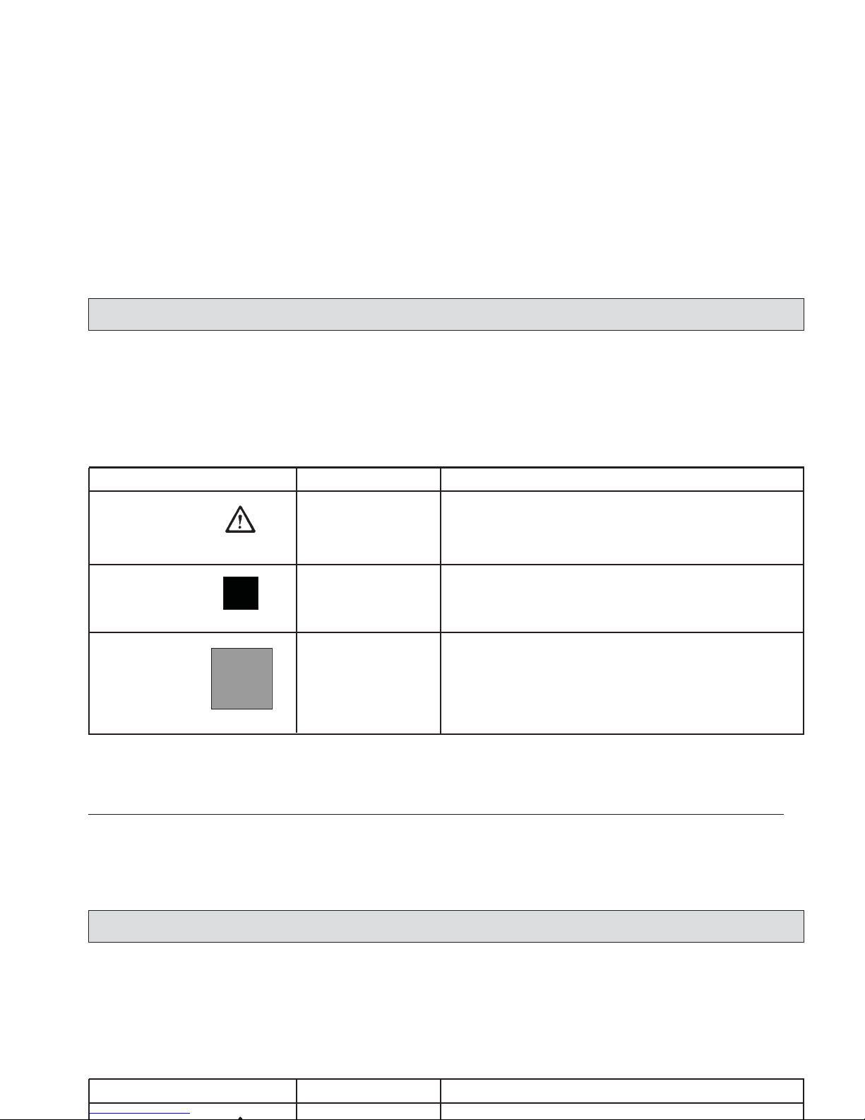
1.2 Safety and Warning Symbols
1.2.1 Generally Applicable Symbols
All paragraphs in this manual referring
to your personal safety, the safety of
your machine and the environment
protection are attributed one of the following warning symbols:
7
Sicherheitsinformationen
Hazardous for....
persons and
goods
the machine
the environment
Description
dangerous situation
caused by imprecise or non-observance of instructions or
prescribed work routine
important information on handling the Apex 47 in order to
maintain operability
due to use of substances representing an inherent danger to
health of environment
Symbol
DANGER
CAUTION
Ecological hazard
1.2 Safety and Warning Symbols
1.2.1 Generally Applicable Symbols
All paragraphs in this manual referring
to your personal safety, the safety of
your machine and the environment
protection are attributed one of the following warning symbols:
Sicherheitsinformationen
Hazardous for....
Description
Symbol
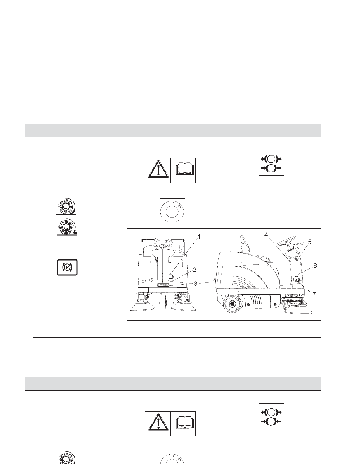
1.3 Labels at the Machine
The following safety and information
signs are legibly attached to the
machine. Missing or illegible stickers
have to be replaced.
Folding apron (1)
Parking brake (2)
PowerBoss nameplate, front and rear (3)
Read and observe
operator's Manual (4)
Key switch (5)
Brake (6)
Noise performance (7)
82 dB (A)
8
Safty Information
Fig.1
1.3 Labels at the Machine
The following safety and information
signs are legibly attached to the
machine. Missing or illegible stickers
have to be replaced.
Folding apron (1)
Read and observe
operator's Manual (4)
Key switch (5)
Brake (6)
Noise performance (7)
82 dB (A)
Safty Information
9
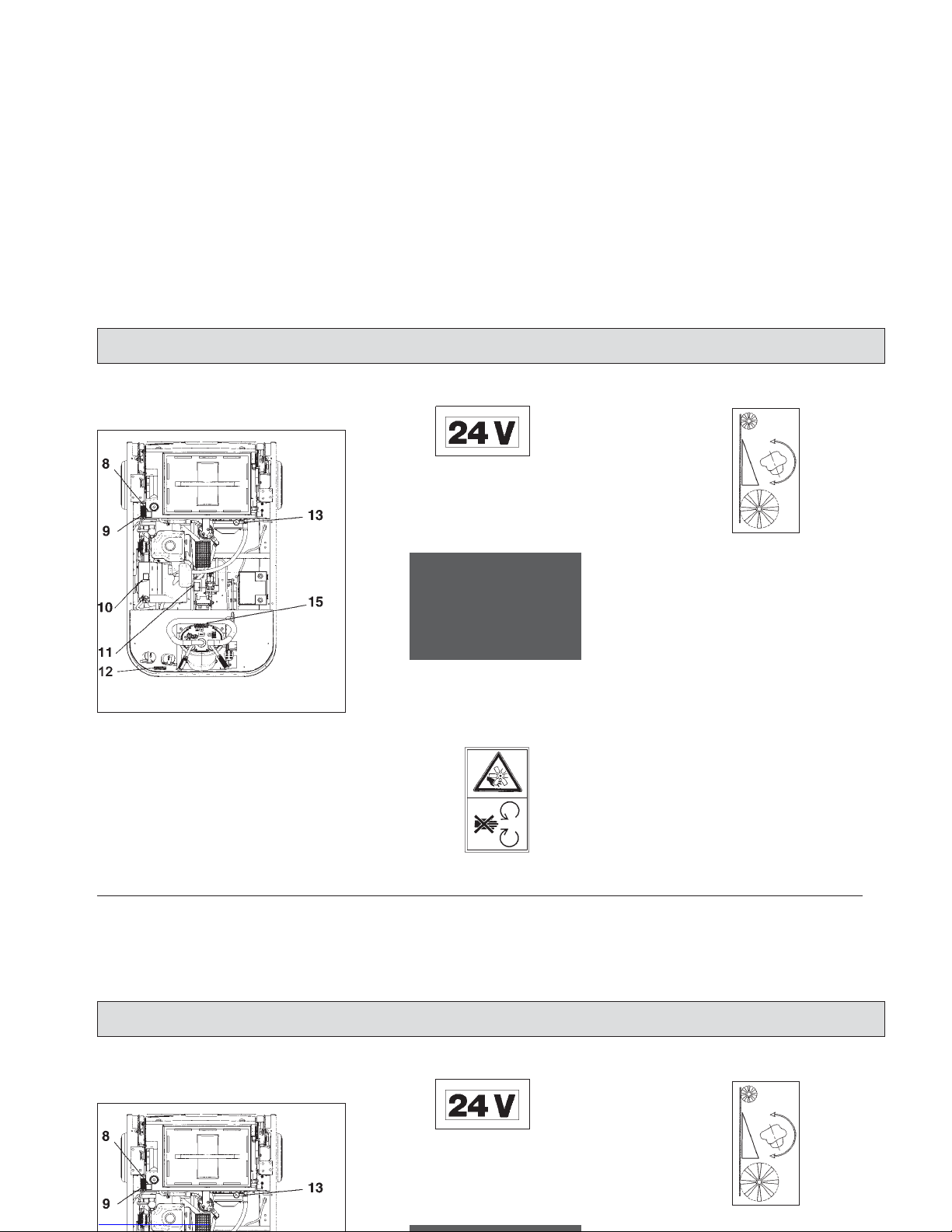
1.3.1 Apex 47 Signs
Safety and information signs
24V label (8)
Battery charging (9)
The label is located under the seat
hood.
Rotating parts (10)
Cylinder broom wearing take-up (11)
Nameplate (12)
Safty Information
Fig.2
1.3.1 Apex 49 Signs
24V label (8)
Battery charging (9)
The label is located under the seat
hood.
Cylinder broom wearing take-up (11)
Safty Information
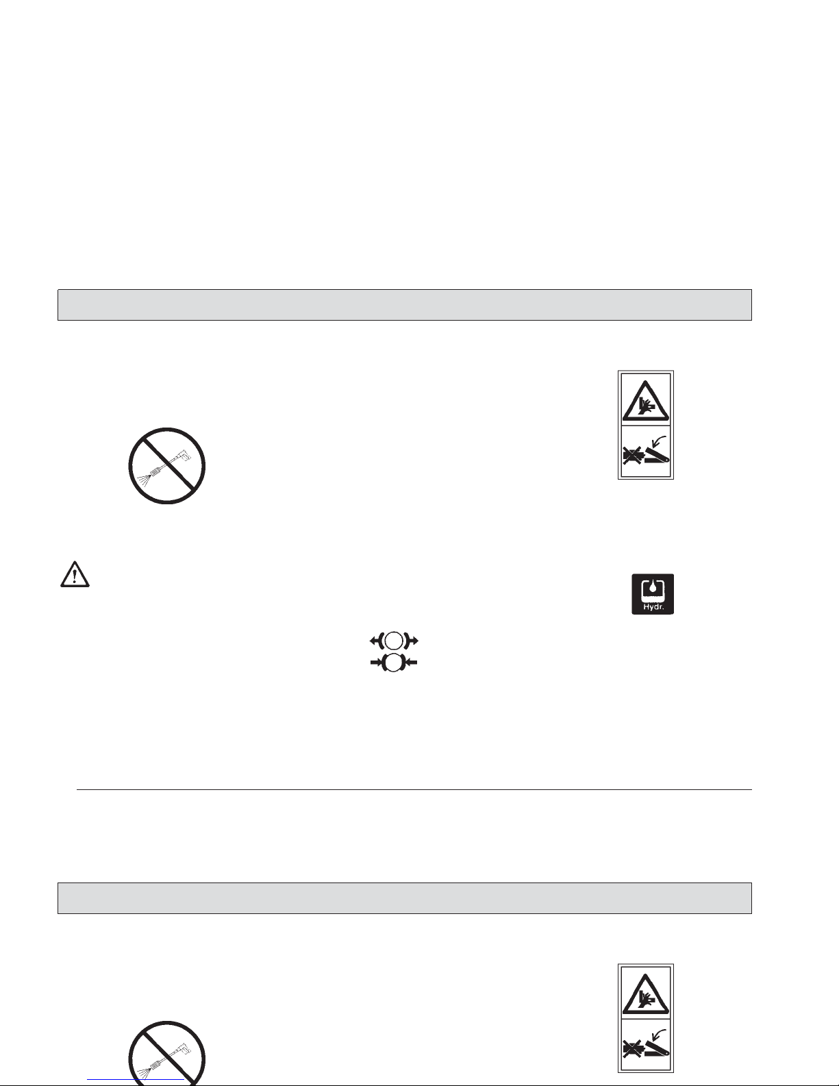
Apex 47 Signs
Continued
High-pressure cleaner (13)
Do not clean by means of
high pressure cleaner or vapour jet.
Apex 47 type name (14)
Brake (15)
Pinching hazard (16)
Hydraulic fluid (17)
10
Safty Information
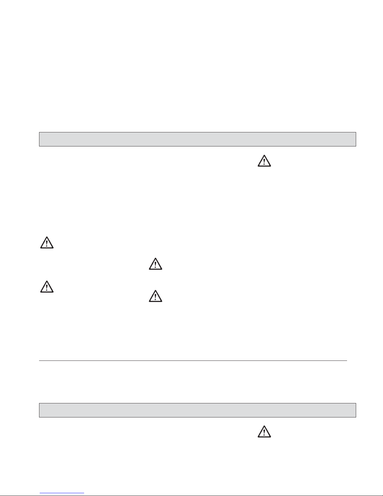
Apex 49 Signs
Continued
High-pressure cleaner (13)
Apex 49 type name (14)
Pinching hazard (16)
Safty Information
11
1.4 Operation/Safety Information
Vacuum sweepers may be run by qualified personnel only; such personnel
will have to have evidenced their qualification for running the machine to
the owner or his authorised representative; operators explicitly will have to
be instructed by the owner or his
authorized representative to use the
machine.
The machine may be used
for cleaning such surfaces
approved by the owner or
this authorised representative for operation of vacuum
sweepers.
Before starting the engine,
switch off all drives
Transporting persons on the machine
is prohibited. Ride-on machine types
are to be started with the driver being
seated.
Never leave the machine unattended
before the motors are off and the machine is protected against unintended
movements.
To prevent the machine from unauthorised use, pull the control key to block
all drives.
Shut down the motors before transport
of the machine. During driving the operator has to take account of local conditions and when working he has to
watch out for other persons, especially
children.
Do not open the hood with
the machine running.
This machine must not be
used as dust-evacuating
machine with dust filter insert (separator) to collect
dusts which are hazardous
to health.
Compared to four-wheeled
vehicles, driving stability of
three-wheeled vehicles is
reduced. We thus recommend:
- do not negotiate curves at
high speed.
- do not turn at slopes but
on level ground only
- ride up- or downhill
straight.
Safty Information
1.4 Operation/Safety Information
Vacuum sweepers may be run by qualified personnel only; such personnel
will have to have evidenced their qualification for running the machine to
the owner or his authorised representative; operators explicitly will have to
be instructed by the owner or his
authorized representative to use the
Never leave the machine unattended
before the motors are off and the machine is protected against unintended
movements.
To prevent the machine from unauthorised use, pull the control key to block
all drives.
Shut down the motors before transport
of the machine. During driving the operator has to take account of local conditions and when working he has to
Compared to four-wheeled
vehicles, driving stability of
three-wheeled vehicles is
reduced. We thus recommend:
- do not negotiate curves at
high speed.
- do not turn at slopes but
on level ground only
- ride up- or downhill
straight.
Safty Information
Warning and instruction labels attached to the machine contain important information about safe operation
Provide for sufficient ventilation when sweeping indoors.
Proceed to filter shaking only after having closed the
dirt hopper.
Do not open the hood with
the machine running.
Proceed to filter shaking only if the dirt hopper is in closed position.
12
Safty Information
1.5 Cleaning Information
The specific safety instructions for
handling drive batteries (see leaflet
88-60-2556) apply. Before proceeding
to cleaning of the machine, pull the
key.
The machine is splash-proof (IPX3).
Do not clean the Apex 47
by means of high pressure
cleaner or vapour jet.
Proceed to cleaning of the
dirt hopper in regular intervals to preclude formation
of bacterial deposits.
Warning and instruction labels attached to the machine contain important information about safe operation
Provide for sufficient ventilation when sweeping indoors.
Proceed to filter shaking only after having closed the
Safty Information
1.5 Cleaning Information
The specific safety instructions for
handling drive batteries (see leaflet
88-60-2556) apply. Before proceeding
to cleaning of the machine, pull the
key.
The machine is splash-proof (IPX3).
13
1.6 Maintenance Instructions
A good approach to prevention of accidents is proper maintenance of the
machine. Before proceeding to repair
or maintenance work pull the key.
Use appropriate tools for maintenance, service, setting etc. As far as
aspects of safety are concerned,
spare parts will have to be at least of
the same quality as the genuine spare
parts.
Switch off the motors before maintaining the machine
or replacing parts of it. Turn
off the machine, pull the key
and, additionally, disconnect the battery plug.
Check hydraulic lines and
hoses for damages and leakage in regular intervals; replace defective hoses and
lines immediately!
Before changing wheels
protect the machine against
rolling by placing wedges.
Proceed to wheel changing
when the machine is on level and solid ground.
Do not repair the pneumatic
tires mounted to the machine yourself. Dismount the
wheel and take it to repair to
qualified workshop.
Use of other than the cylinder brooms and side brushes approved by the manufacturer is not admitted (see
technical data) since use of
other cylinder brooms and
side brushes may affect
your safety.
When handling lubrica-
ting agents, the applicable regulations for
protection of the environment and
prevention of fire have
to be complied with.
Provide for disposal of
used oil and grease in
accordance with the
provisions imposed by
law.
Collect cleaning
agents, oil, fuel oil,
grease etc. and provide for adequate disposal. Wipe away spilled
substances.
Specific safety instructions for handling batteries apply (refer to leaflet
88-60-2556 for further safety provisions)
Safty Information
1.6 Maintenance Instructions
A good approach to prevention of accidents is proper maintenance of the
machine. Before proceeding to repair
or maintenance work pull the key.
Use appropriate tools for maintenance, service, setting etc. As far as
aspects of safety are concerned,
spare parts will have to be at least of
Before changing wheels
protect the machine against
rolling by placing wedges.
Proceed to wheel changing
when the machine is on level and solid ground.
Do not repair the pneumatic
tires mounted to the machine yourself. Dismount the
wheel and take it to repair to
When handling lubrica-
ting agents, the applicable regulations for
protection of the environment and
prevention of fire have
to be complied with.
Provide for disposal of
used oil and grease in
accordance with the
provisions imposed by
Safty Information
Specific safety instructions for
handling batteries apply
(refer to leaflet 88-60-2556
"Information on Drive Batteries" for
further safety provisions).
Before commencing any
work on the electric system
disconnect battery plug of
the Apex 47.
Do not keep batteries
discharged for a longer
period; always recharge
them as soon as possible.
T
op with distilled water only.
Never refill battery acid in
battery cells of perfect
condition.
Open the hood before
charging batteries;
explosive gases may occur
during the charging
procedure.
Keep batteries dry and clean and clear of soiling such
as e.g. metallic dust to avoid leakage current.
Do not place metal objects
or tools onto batteries.
Short-circuit and deflagration hazard.
Spilled (straight) battery
acid must not get into the
sewage system before having been neutralised. Comply with the regulations imposed by law and observe
local provisions.
Battery acid is highly
caustic (keep clear of children). When checking the
battery acid level, wear safety glasses. If acid splashes get into the eyes rinse
with clear water for 15 minutes and contact a doctor immediately.Wear appropriate
protective clothes (e.g. protective gloves or
finger-stalls) when handling
battery acid.
Do not use open flames (explosion hazard).
Do not eat, smoke or drink
in rooms where batteries
are charged to avoid damaging your health. After work
with batteries wash your
hands thoroughly. Provide
for sufficient ventilation.
14
Safty Information
Specific safety instructions for
handling batteries apply
(refer to leaflet 88-60-2556
"Information on Drive Batteries" for
further safety provisions).
Before commencing any
work on the electric system
disconnect battery plug of
Keep batteries dry and clean and clear of soiling such
as e.g. metallic dust to avoid leakage current.
Do not place metal objects
or tools onto batteries.
Short-circuit and deflagration hazard.
Spilled (straight) battery
finger-stalls) when handling
battery acid.
Do not use open flames (explosion hazard).
Do not eat, smoke or drink
in rooms where batteries
are charged to avoid dama-
Safty Information

15
Safty Information
1.7 Accident Prevention Regulations
BGV D 29 Vehicles
According to BGV D 29, the Apex 47 vacuum sweeper has to be inspected for
safe condition by an authorized expert as required, but not less than once a year.
Results of such an inspection have to be kept on file at least until the next inspection is
performed.
BGV D 27 Industrial trucks
Observe as well: - the applicable provisions for Safety and Health at Work and the Fire Regulations
- internal safety provisions
Safty Information
1.7 Accident Prevention Regulations
BGV D 29 Vehicles
According to BGV D 29, the Apex 49 vacuum sweeper has to be inspected for
safe condition by an authorized expert as required, but not less than once a year.
Results of such an inspection have to be kept on file at least until the next inspection is
performed.
BGV D 27 Industrial trucks
Observe as well: - the applicable provisions for Safety and Health at Work and the Fire Regulations
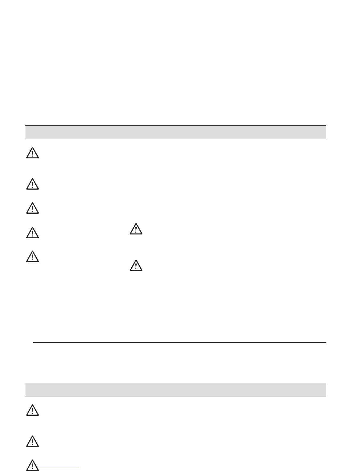
2 Description
2.1 Functional Description
2.1.1 Principle of Apex 47
Principle of
Apex 47 B
The side brushes are used to collect
dirt at borders and to enlarge the working width as well as to increase the
area performance on large surfaces.
The cylinder broom transports the
debris into the dirt hopper. The suction
fan vacuums the fine dirt which is
separated by a filter system. The air
returned into the environment is clean.
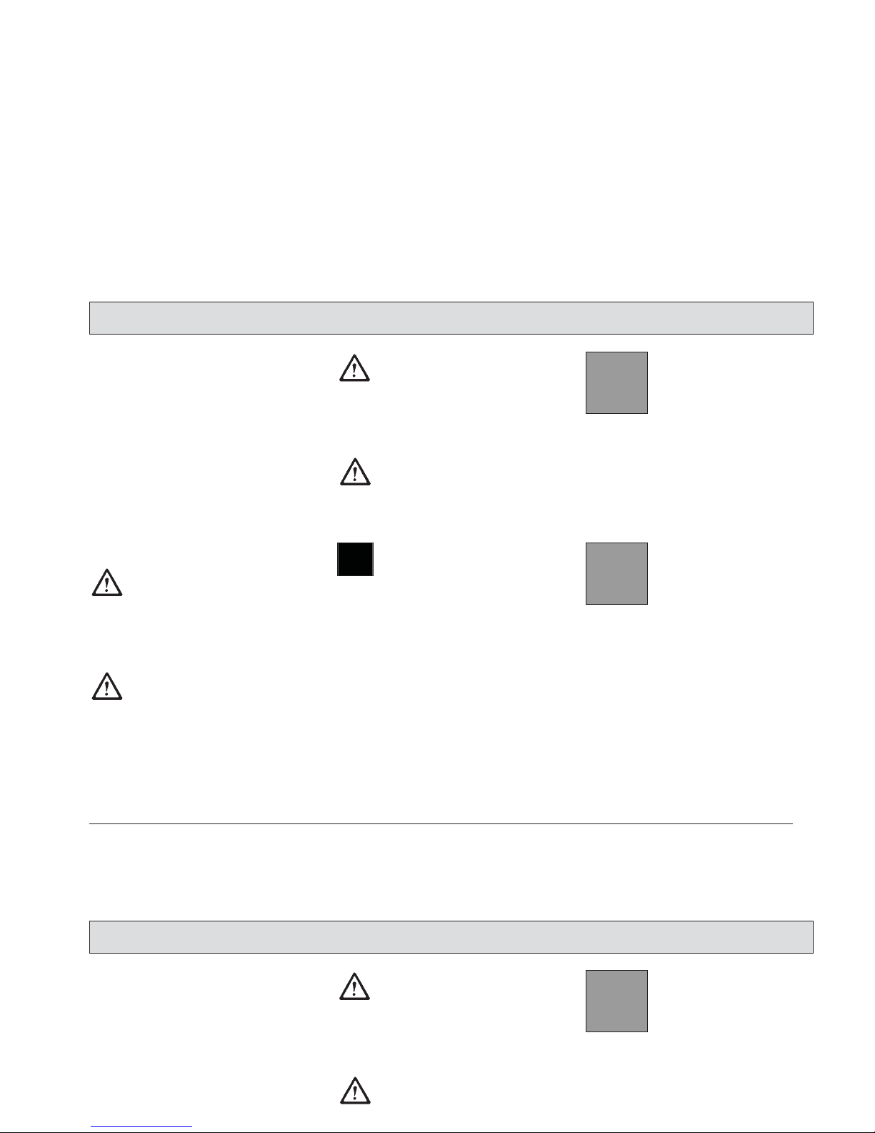
2.1.2 Principle of Apex 47 BH
Principle of
Apex 47 BH
16
Description
Fig.3
Fig.4
2 Description
2.1 Functional Description
2.1.1 Principle of Apex 49
The side brushes are used to collect
dirt at borders and to enlarge the working width as well as to increase the
area performance on large surfaces.
The cylinder broom transports the
debris into the dirt hopper. The suction
fan vacuums the fine dirt which is
separated by a filter system. The air
returned into the environment is clean.
2.1.2 Principle of Apex 49 BH
Description

17
2.2 Cylinder Broom
The cylinder broom is equipped with
12 rows of bristles arranged in Vshape.
The cylinder broom width amounts to
700mm and its diameter to 345mm.
2.3 Side Brush
The standard version, the side brush
is located at the front right of the
machine. The operator lifts and lowers
it by hand lever.
The side brush is to have a light inclination.
The swinging area of the side brush
arm is limited by stop screws.
The side brush is driven by V-belt.
For special application, fitting of a
second side brush at the left is possible.
2.4 Filter System / Dust Evacuation
The filter system is located in the filter
case above the dirt hopper. The suction fan transports the fine dust raised
by the cylinder broom to the plate filter
where it is separated. The fine dusts
sets at the outsides of the filter blades.
In case of heavy dust deve-
lopment, check and clean
the plate filter at regular
intervals.
2.5 Shaking System
Due to normal working vibration the
set dust partly falls off into the dirt
hoper. To ensure working in a dustfree ambiance, however, actuate the
shaking system regularly.
2.6 Steering
Steerage is effectuated mechanically
from steering wheel to front wheel via
chain. This chain is to be re-adjusted
as required.
2.7 Wheels
Front wheel: solid rubber tires
Rear wheels: solid rubber tires
Description
2.2 Cylinder Broom
The cylinder broom is equipped with
12 rows of bristles arranged in Vshape.
The cylinder broom width amounts to
700mm and its diameter to 345mm.
2.4 Filter System / Dust Evacuation
The filter system is located in the filter
case above the dirt hopper. The suction fan transports the fine dust raised
by the cylinder broom to the plate filter
where it is separated. The fine dusts
sets at the outsides of the filter blades.
2.6 Steering
Steerage is effectuated mechanically
from steering wheel to front wheel via
chain. This chain is to be re-adjusted
as required.
2.7 Wheels
Front wheel: solid rubber tires
Description

2.8 Brake
The Apex 47 is equip-
ped with a service brake.
This brake has been constructed as
shoe brake and equally serves as parking brake.
It is located in the rear wheels and is
actuated via cables.
A special adjustment screw is situated
at the right-hand rear wheel.
Works at the braking
system have to be executed
by qualified persons in a
qualified workshop only.
2.9 Travel Drive Assembly
The Apex 4
7 is equipped with an
electric drive assembly with
continuous regulation.
2.10 Hydraulic
System
The hydraulic system includes a
compact unit (hydraulic pump with
hydraulic tank) as well as hydraulic
hoses and a hydraulic cylinder.
Hydraulic fluid: Mobiloil DTE 15 M
The hydraulic system has been filled
with fluid in the factory.
Filling of hydraulic fluid tank: 0.76 litre
18
Description
2.8 Brake
The Apex 49 is equip
ped with a service brake.
This brake has been constructed as
shoe brake and equally serves as parking brake.
It is located in the rear wheels and is
actuated via cables.
A special adjustment screw is situated
2.9 Travel Drive Assembly
The Apex 49 is equipped with an
electric drive assembly with
continuous regulation.
2.10 Hydraulic System
The hydraulic system includes a
compact unit (hydraulic pump with
Description

19
3 Battery Systems
Before commencing any
work on the electric system
disconnect the battery plug.
Do not use open flames
when handling batteries and
especially when checking
the battery acid level. Provide for sufficient ventilation
in rooms where batteries
are charged. Spilled
(straight) battery acid must
not get into the sewage
system before having been
neutralised.
Comply with the regulations
imposed by law and observe local provisions.
Open the hood before charging batteries; explosive gases may occur during the
charging procedure.
Battery Systems
3 Battery Systems
Before commencing any
work on the electric system
disconnect the battery plug.
Do not use open flames
when handling batteries and
especially when checking
the battery acid level. Provide for sufficient ventilation
in rooms where batteries
are charged. Spilled
(straight) battery acid must
Battery Systems

3.1 Low Discharge Signal Sender
Battery charging status
indicator/hourmeter
The factory setting is as follows:
maintenance-free block battery, 4x6V block batteries,
type: GiV
3.1.1 Battery Charging Status Indicator
Upon turning ON by key switch, battery charging status is shown by display of green bars (Fig. 5/1). As the
battery discharges during operation,
the lighting green bars extinguish one
after another showing thus always the
current charge status of battery charge.
Flashing of the last two green bars
indicates that operation will be stopped soon. In order to preclude low
discharge of batteries, the sweeping
units are switched off and riding speed
reduced to 50% if battery is discharged. The red LED (Fig. 5/4) than flashes.
3.1.2 Hourmeter
The operating hours of the machine
appear in the display (Fig. 5/2); the
hourmeter will count only during working or transport ride; only full hours
are displayed).
3.1.3 Setting Other Battery Types
Have the low discharge signal sender set to other battery types by qualified personnel only and in
approved qualified workshops only.
20
Battery Systems
Fig.5
3.1 Low Discharge Signal Sender
3.1.1 Battery Charging Status Indicator
Upon turning ON by key switch, battery charging status is shown by display of green bars (Fig. 5/1). As the
battery discharges during operation,
the lighting green bars extinguish one
after another showing thus always the
current charge status of battery charge.
3.1.3 Setting Other Battery Types
Have the low discharge signal sender set to other battery types by qualified personnel only and in
approved qualified workshops only.
Battery Systems

21
3.2 Plug Connection Coding
The battery plugs of the machine, the
battery and the stationary charger unit
have to be coded according to the battery type and the nominal voltage with
coloured pins.
The charger unit's plugs are/will be
coded in the factory according to the
characteristic curve and changing the
characteristic curve (according to the
battery type) always requires modification of the plug coding.
Plug case of charger unit:
- grey for wet batteries
- green for maintenance-free
Gel batteries
Machine plug case:
- yellow for both battery types
Battery socket case:
- grey for wet batteries
- green for maintenance-free
Gel batteries
Remove the coding pin by pressing the
ends together by means of pliers.
Press together for assembly
Insert pin such that the nominal voltage inscription is visible through the case window. Socket and plug always
with the same nominal voltage!
The following three requirements have
to be met:
1) Voltage coding is the same for all
plugs and sockets
2) Coding pin colour in the machine =
yellow
3) Coding pin colour
Before first operation of the
machine, the batteries have
to be adequately charged by
an initial charging procedure. Please observe the instructions of the charger
unit's operating manual.
Powerboss rejects any claim for
warranty on battery damages caused by unfulfilled initial charging.
Battery Systems
Nominal voltage value for
plug printed on each side
of the hexagon (letters
upside down)
Inscription for nominal voltage for sokkets accordingly
3.2 Plug Connection Coding
The battery plugs of the machine, the
battery and the stationary charger unit
have to be coded according to the battery type and the nominal voltage with
coloured pins.
The charger unit's plugs are/will be
coded in the factory according to the
characteristic curve and changing the
The following three requirements have
to be met:
1) Voltage coding is the same for all
plugs and sockets
2) Coding pin colour in the machine =
yellow
3) Coding pin colour
Before first operation of the
Battery Systems
Nominal voltage value for
plug printed on each side
of the hexagon (letters
upside down)
Inscription for nominal voltage for sokkets accordingly

22
Battery Systems
Battery Systems

23
4 First Operation
Before delivery, the Apex 47
has been extensively tested and
submitted to a functional check.
Only qualified personnel of your local
Powerboss contact dealer are allowed
to proceed to first operation. After shipping of the machine, we advise your
Powerboss contact dealer. He will
contact you to make a date for briefing
lessons.
4.1 First Operation of Batteries
To achieve the optimum performance
and a maximum service life, the batteries must be given the initial charge
after filling.
Handling and function of the battery
charger is described in detail in the
instruction manual supplied with each
charger unit.
Since batteries and charger
units are matched, we recommend using batteries
and chargers as prescribed
by PowerBoss. We can grant full
warranty only if those units
are being used.
For further information on first operation, maintenance and service of batteries refer to the leaflet 88-60-2556
"Information on drive batteries".
Do not use the Apex 4
7
at ambient tempe
ratures of more than 40°C.
Do not start the machine at
temperatures of 0°C or less.
First Operation
4 First Operation
Before delivery, the Apex 49
has been extensively tested and
submitted to a functional check.
Only qualified personnel of your local
Powerboss contact dealer are allowed
to proceed to first operation. After shipping of the machine, we advise your
Powerboss contact dealer. He will
Since batteries and charger
units are matched, we recommend using batteries
and chargers as prescribed
by Minuteman. We can grant full
warranty only if those units
are being used.
For further information on first operation, maintenance and service of batteries refer to the leaflet 88-60-2556
First Operation

4.2 Insert Batteries
- Turn engine off and pull key
- Secure machine by engaging the
parking brake.
- Fold back seat hood.
- Insert batteries into the battery tray
from the top.
Insert batteries
6V/240Ah, GiV maintenance-free
- Connect batteries and enclosed cable set according to Fig. 7 (check for
tight seating) and grease poles.
- Check set battery type at the low discharge signal sender or set if
required.
- Connect charging plug of the battery
connection cable and cable of the
charger unit and proceed to initial
charging.
- After charging of the batteries, connect charger plug and device plug
for electrical connection.
Now the Apex 4
7 is
operable.
If the battery type setting at
the LDS should be incorrect, have the setting modified by qualified personnel
in an approved workshop.
24
First Operation
Fig.6
Fig.7
4.2 Insert Batteries
- Turn engine off and pull key
- Secure machine by engaging the
parking brake.
- Fold back seat hood.
- Insert batteries into the battery tray
from the top.
- After charging of the batteries, connect charger plug and device plug
for electrical connection.
Now the Apex 49 is
operable.
If the battery type setting at
the LDS should be incorrect, have the setting modi-
First Operation

25
24V/210Ah tray battery, EPzB
with Aquamatik
- Turn machine off and pull key.
- Secure machine by actuating parking brake.
- Fold up seat hood
- Insert battery
- Connect charging plug of the battery
connection cable and cable of the
charger unit and proceed to initial
charging.
- After charging of the batteries, connect charger plug and device plug
for electrical connection.
If the battery type setting at
the LDS should be incorrect, have the setting modified by qualified personnel
in an approved workshop.
Use admitted lifting and
transport devices such as
e.g. lifting tackles according
to VDI 3616. Make sure that
lifting hooks do not damage
cells, connectors or connecting cables.
First Operation
Fig.8
- Turn machine off and pull key.
- Secure machine by actuating parking brake.
- Fold up seat hood
- Insert battery
- Connect charging plug of the battery
connection cable and cable of the
charger unit and proceed to initial
charging.
- After charging of the batteries, connect charger plug and device plug
First Operation

5 Operation
5.1 Apex 47 Controls
1 Actuator for folding apron
2 Service brake lock
3 Service brake/parking brake pedal
4 Drive pedal, reverse
5 Drive pedal, forward
6 Control panel
7 Seat adjustment
26
Operation
Fig.9
5 Operation
5.1 Apex 49 Controls
1 Actuator for folding apron
2 Service brake lock
3 Service brake/parking brake pedal
4 Drive pedal, reverse
5 Drive pedal, forward
6 Control panel
Operation

27
1 Actuator for folding apron
to open and close the folding apron
for collecting coarse dirt.
2 Service brake/parking brake lock
to lock the service brake/parking
brake. If locked, the service brake
works as parking brake. Release
the lock by depressing the service
brake pedal (3).
3 Service brake/parking brake
pedal
to actuate the service brake at the
rear wheels. Before leaving the
machine unattended, engage the
service brake and lock.
4 Drive pedal, reverse
to change direction to reverse ride
and with continuous regulation of
riding speed at the same time. If
the driver lets the pedal go it returns to initial position and the machine slows down to standstill.
5 Drive pedal, forward
to change direction to forward ride
and with continuous regulation of
riding speed at the same time. If
the driver lets the pedal go it returns to initial position and the machine slows down to standstill.
6 Control panel
Refer to chapter "Control panel"
7 Seat adjustment
to adjust the seat position to drivers of different height.
Adjust the seat so as to allow the
driver being comfortably seated
and attaining all elements required
for operation.
- Adjust seat lengthwise: push lever
slightly to the right and displace seat
forwards or backwards to the required
position. Then let the lever catch
again.
Operation
1 Actuator for folding apron
to open and close the folding apron
for collecting coarse dirt.
2 Service brake/parking brake lock
to lock the service brake/parking
brake. If locked, the service brake
works as parking brake. Release
the lock by depressing the service
brake pedal (3).
4 Drive pedal, reverse
to change direction to reverse ride
and with continuous regulation of
riding speed at the same time. If
the driver lets the pedal go it returns to initial position and the machine slows down to standstill.
5 Drive pedal, forward
7 Seat adjustment
to adjust the seat position to drivers of different height.
Adjust the seat so as to allow the
driver being comfortably seated
and attaining all elements required
for operation.
- Adjust seat lengthwise: push lever
slightly to the right and displace seat
Operation

5.2 Apex 47 Control
Panel
1 Cylinder broom lever
2 Release (lifted-up disposal)
Ampex BH
3 Horn
4 Cover with plug connection for
battery/LDS programming
5 Suction fan/shaking system knob
6 Flashlight (optional)
7 Lighting (optional)
8 Lift and lower (lifted-up disposal)
9 Side brush lever
10 Pilot lamp, parking brake
11 Battery charge status
indicator/hourmeter
12 Pilot lamp, fan
13 Pilot lamp, shaking system
28
Operation
Fig.10
5.2 Apex 49 Control
Panel
1 Cylinder broom lever
2 Release (lifted-up disposal)
Ampex BH
3 Horn
4 Cover with plug connection for
battery/LDS programming
5 Suction fan/shaking system knob
6 Flashlight (optional)
Operation

29
1 Cylinder broom lever
to lift and lower as well as to switch
on and off the cylinder broom and
the side brush.
- Lower cylinder broom as well as
switch on cylinder broom and side
brush = push lever
- Lift cylinder broom as well as switch
off cylinder broom and
side brush = pull lever
2 Release (lifted-up disposal)
Apex BH
to release the lifted-up disposal.
Has to be actuated before
activation of lifting/lowering
lifted-up disposal function.
Hold the key during
lifting/lowering.
Before changing lifting to
lowering or vice versa, the
"Release Lifted-Up Disposal" key has to be released
once and pressed again
3 Horn
An acoustic signals sound upon actuation of this button.
4 Cover with plug connection for
battery/LDS programming
Remove this cover to modify setting of
battery type. The plugged connections
of the programming cable are located
there.
Have the programming exe-
cuted by a PowerBoss
contract dealer with qualified
personnel at hand.
Operation
1 Cylinder broom lever
to lift and lower as well as to switch
on and off the cylinder broom and
the side brush.
2 Release (lifted-up disposal)
Apex BH
to release the lifted-up disposal.
Has to be actuated before
3 Horn
An acoustic signals sound upon actuation of this button.
Operation

5 Suction fan/shaking system
knob
Knob position (from bottom to top
position):
Pos. 0 Activated vacuuming
function (close flap before sweeping dry surfaces or collecting dry
dirt).
Pos. 1 Deactivated vacuuming function (open flap before
sweeping wet surfaces and collecting wet dirt).
Pos. 2 Shaking system ON
(pull knob to stop and then release)
If the yellow pilot lamp (Fig. 9/13)
lights, actuate the shaking system
(position 2).
In this position, the shaking system is
operable and proceeds to jolting in 7
repeated intervals.
After jolting, the knob is to
be kept in position 1 for
about 10 seconds. Switch
off the main broom before
and do not turn on during
jolting.
6 Flashlight (optional)
to switch the flashlight ON/OFF.
7 Lighting (optional)
to switch the driving headlight
ON/OFF.
8 Lift and lower (lifted-up disposal)
to lift and lower the dirt hopper.
Lift the dirt hopper by pressing the key
until the desired height for lifting-out is
attained.
When lowering the dirt hopper make
sure to hold the key pressed until the
hopper has contact with the frame.
30
Operation
5 Suction fan/shaking system
If the yellow pilot lamp (Fig. 9/13)
lights, actuate the shaking system
(position 2).
In this position, the shaking system is
operable and proceeds to jolting in 7
repeated intervals.
After jolting, the knob is to
be kept in position 1 for
7 Lighting (optional)
to switch the driving headlight
ON/OFF.
Operation

31
Actuate release key for lif-
ted-up disposal and hold
before lifting or lowering.
9 Side brush lever
to lift and lower the side brush.
- Lower side brush = push lever
- Lift side brush = pull lever
10 Pilot lamp, parking brake (red)
lights upon actuation of the parking
brake
Extinguishes upon release of the parking brake.
11 Battery charge status indicator
Refer to paragraph 3.1.1
Hourmeter
Refer to paragraph 3.1.2
12 Pilot lamp, suction fan (orange)
lights if the suction fan is not
activated.
Operation
Actuate release key for lif-
ted-up disposal and hold
before lifting or lowering.
10 Pilot lamp, parking brake (red)
lights upon actuation of the parking
brake
Extinguishes upon release of the parking brake.
12 Pilot lamp, suction fan (orange)
lights if the suction fan is not
activated.
Operation

13 Pilot lamp, shaking system
(yellow)
Proceed to jolting of the filter system
upon lighting of this pilot lamp by actuating the knob (Fig. 10/5).
The pilot lamp flashes during the shaking procedure
and extinguishes after low
pressure has been attained
in the filter system. Jolting
is effectuated in 7 intervals.
14 Key switch
to switch the machine on and off and
to secure it against unauthorised use.
32
Operation
13 Pilot lamp, shaking system
(yellow)
Proceed to jolting of the filter system
upon lighting of this pilot lamp by actuating the knob (Fig. 10/5).
14 Key switch
to switch the machine on and off and
to secure it against unauthorised use.
Operation

33
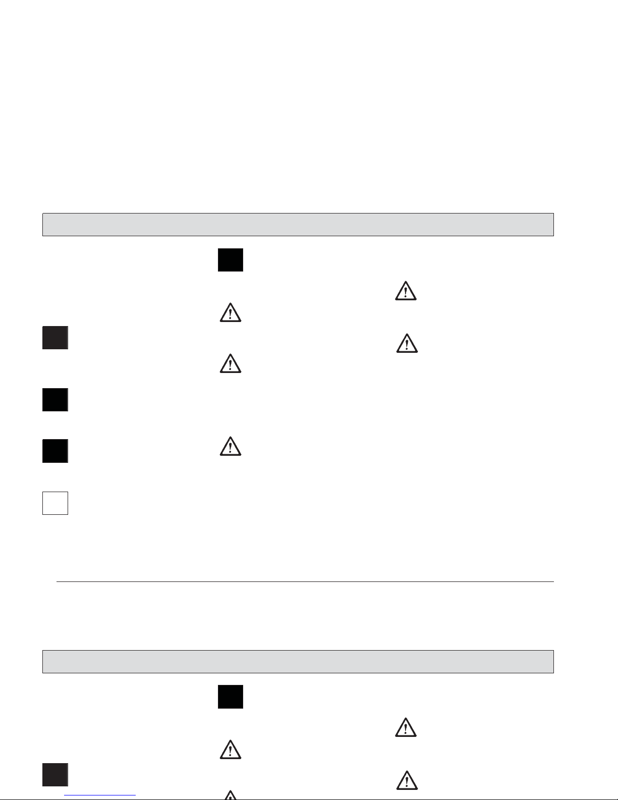
5.3 Empty Dirt Hoppers of
Apex 47 B
- Fold bow (Fig. 11/3) up = the dirt
hoppers (Fig. 11/2) are lowered.
- Use the recessed grip (Fig. 11/1) of
one of the hoppers to lift it lightly
and extract it.
- Take the hopper at its bow-type
handle to disposal and empty.
- Empty second dirt hopper as described above.
- Re-insert dirt hopper (Fig. 11/2) and
fold down the bow (Fig. 11/3).
Emptying dirt hopper Apex 47
1 Recessed grip in dirt hopper
2 Dirt hopper
3 Bow to lift/lower dirt hoppers
Clean dirt hoppers at
regular intervals.
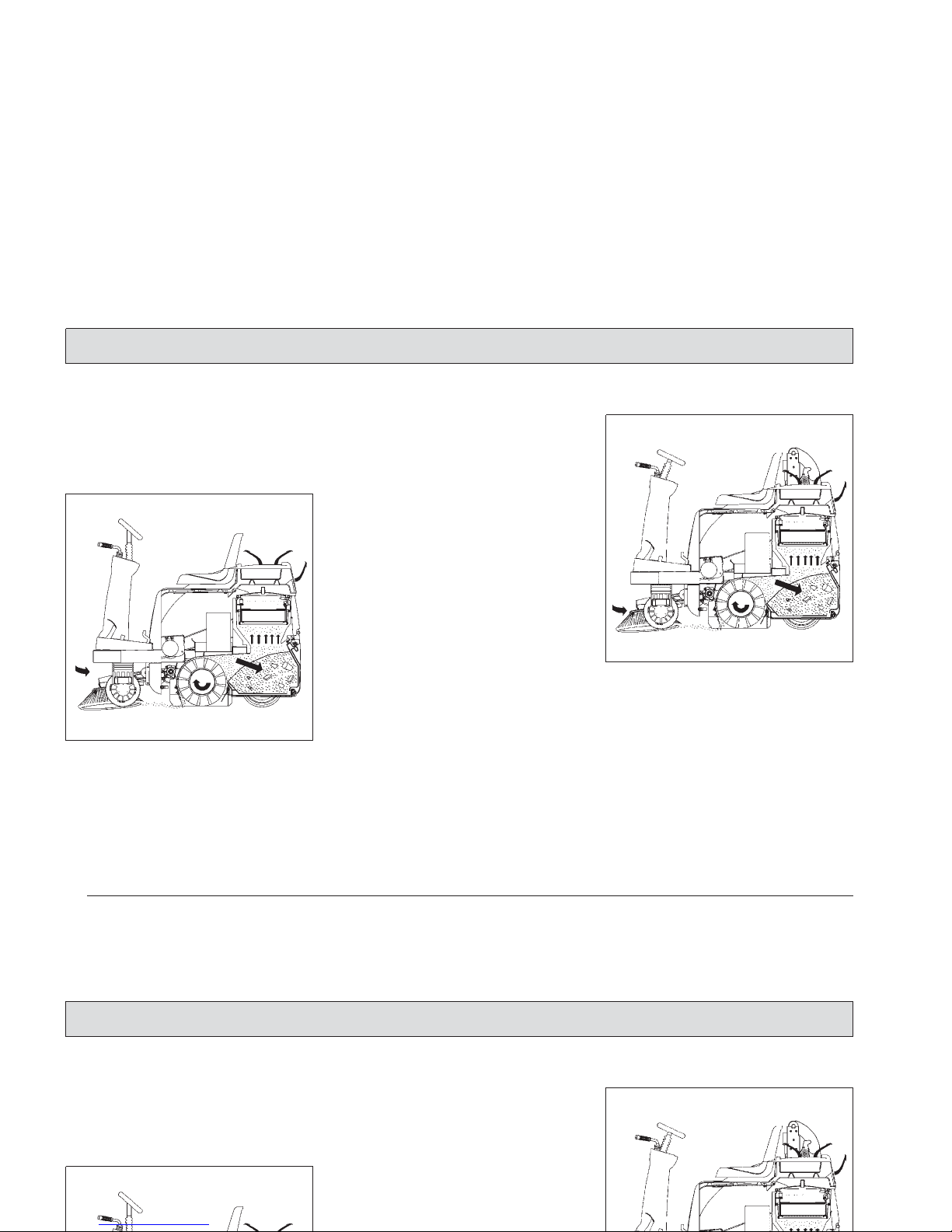
5.4 Empty Dirt Hopper of
Apex 4
7 BH
Before emptying the turning property container the
side broom and the turning
roller are to be raised and
switched off.
Broom and fan will be autmatically switched ON upon
lowering of the hopper if cylinder broom has been ON
before lifting.
The driving speed forward
and backwards with dug
turning property container
is reduced to 50 %, the turning roller is switched off.
Emptying dirt hopper Apex
47 BH
1 Lift-out arm
2 Lift-out cylinder
3 Dirt hopper
Operation
Fig.11
Fig.12
5.3 Empty Dirt Hoppers of
Apex 49 B
- Fold bow (Fig. 11/3) up = the dirt
hoppers (Fig. 11/2) are lowered.
- Use the recessed grip (Fig. 11/1) of
one of the hoppers to lift it lightly
and extract it.
- Take the hopper at its bow-type
handle to disposal and empty.
- Empty second dirt hopper as descri-
Clean dirt hoppers at
regular intervals.
5.4 Empty Dirt Hopper of
Apex 49 BH
Before emptying the turning property container the
side broom and the turning
roller are to be raised and
Operation

Lift side brush and cylinder
broom before removal of
the dirt hopper.
Riding with the lifted hopper
reduces stability of the machine significantly. For this
reason, do not lift the hopper but just before emptying. Before lifting the hopper, the operator has to
make sure that no persons
or objects are behind or
next to the machine. Stop
the machine on level
ground before lifting the
hopper.
Keep clear of the hazard zone!
Pinching and shearing hazard. Provide for required
safe distance before lifting
or lowering the dirt hopper.
Apex 47H control panel
1 Release switch for lifted-up disposal
function
2 Dirt hopper, lift and lower
Proceed to emptying of the dirt
hopper as follows:
- Lift side brush and cylinder broom
- Proceed to shaking of the filter
system
- Actuate switch (Fig. 13/1) and hold
(dirt hopper is released)
- Actuate switch (Fig. 13/2) by
pushing = lift dirt hopper
- Dirt hopper (Fig. 12/3) is lifted-out
- Back the Apex 4
7H until the dirt
hopper is positioned above the
container for disposal.
-
Pull the safety knob (Fig. 14/1) of
the release lever (Fig. 14/2).
- Release swinging of the dirt hopper
by release lever (fig. 14/2).
- The Apex 47 away from the
disposal container forward drive.
- Lower dirt hopper by actuating
switch (Fig. 13/1) and switch (Fig.
13/2) = lower dirt hopper
34
Operation
Fig.13
Lift side brush and cylinder
broom before removal of
the dirt hopper.
Riding with the lifted hopper
reduces stability of the machine significantly. For this
reason, do not lift the hopper but just before emptying. Before lifting the hop-
Pinching and shearing hazard. Provide for required
safe distance before lifting
or lowering the dirt hopper.
Proceed to emptying of the dirt
hopper as follows:
- Lift side brush and cylinder broom
- Proceed to shaking of the filter
system
- Actuate switch (Fig. 13/1) and hold
(dirt hopper is released)
- Actuate switch (Fig. 13/2) by
pushing = lift dirt hopper
- Dirt hopper (Fig. 12/3) is lifted-out
Operation
35
Observe the information gi-
ven in paragraph 5.2 on
releasing of lifted-up disposal.
Sweeping is possible only
after the dirt hopper has attained its working position.
Release lever, swing dirt hopper
1 Safety knob
2 Release lever, swing dirt hopper
Should the dirt hopper not
be completely emptied after
swinging, proceed to manual shaking with the handle
(Fig. 12/4).
Clean the dirt hopper in regular intervals.
Max. filling of the dirt hopper is 70 litres. Do not exceed a filling of 110kg.
Operation
Fig.14
Observe the information gi-
ven in paragraph 5.2 on
releasing of lifted-up disposal.
Sweeping is possible only
after the dirt hopper has attained its working position.
Should the dirt hopper not
be completely emptied after
swinging, proceed to manual shaking with the handle
(Fig. 12/4).
Clean the dirt hopper in regular intervals.
Operation

5.5 Working with the Apex 47
The driver is requested to carefully
read this operator's manual. All controls are marked with easy-to-understand symbols that ease familiarization. First driving attempts should be
limited to clear areas until you are
familiar with all controls and their functions.
Please comply with the following safety provisions:
When working with the
Apex 47 all sa
fety measures generally applicable for handling vehicles and fuels have to be
observed. No p
assenger
transport admitted with the
Apex 47. War
ning and instruction labels
attached to the machine
contain important information about safe operation
and guarantee your personal safety. Before commencing work,
the operator has to make
sure that the machine and
its accessories are in proper
and safe condition and
comply with the provision
for safety at work. Do not
operate the Apex 47
without protective de
vices.
5.5.1 Switch Electro-Motor ON and
OFF
For safety reasons, the
Apex 47 is equipped with a
seat contact switch.
Starting the engine or
running engine is possible
only when the driver is
seated. If the seat contact
switch is activated with the
electro-motor running, reset
by turning the key switch
OFF and ON again.
- Switch all levers and switches to
neutral position.
- Actuate parking brake
- Turn key switch to "I"
Check the drive pedal for
being in neutral position before switching ON.
If the Apex 4
7
is not used within the admissible conditions and environments of use, the protective functions may
respond and switch off driving function without prior
warning.
Slow the machine down to
standstill by the service brake in that case.
Acknowledge protective
function by key switch.
Overheating of the travel
drive assembly or control
module always entails a
cooling phase.
The seat contact switch deactivated all functions, driving function included.
Slow the machine down to
standstill by the service brake in that case.
36
Operation
5.5 Working with the Apex 49
The driver is requested to carefully
read this operator's manual. All controls are marked with easy-to-understand symbols that ease familiarization. First driving attempts should be
limited to clear areas until you are
familiar with all controls and their functions.
the operator has to make
sure that the machine and
its accessories are in proper
and safe condition and
comply with the provision
for safety at work. Do not
operate the Apex 49
without protective de
vices.
5.5.1 Switch Electro-Motor ON and
Check the drive pedal for
being in neutral position before switching ON.
If the Apex 49
is not used within the admissible conditions and environments of use, the protective functions may
respond and switch off driving function without prior
Operation

37
5.5.2 Sweep
- Lower cylinder broom.
- Release parking brake.
- Slowly depress drive pedal until
desired speed has been attained.
- Regularly actuate shaking device to
clean plate filter.
- Check filling level of the dirt hopper
and empty if required.
5.5.3 Stop and Park
- Release drive pedal which returns
automatically into its neutral position
and the machine slows down to
standstill and actuate service brake.
- Actuate parking brake
- Lift side brush and cylinder broom
- Turn key switch to "0"
When leaving the machine
unattended, pull key.
5.5.4 Displace
Make sure that the key switch is in
neutral position and the side brush
and cylinder broom are lifted up before
displacement of the machine.
5.5.5 Transport
Before transporting the machine on other vehicles, engage the parking brake
and secure the machine by straps and
by placing wedges at the wheels.
Operation
5.5.2 Sweep
- Lower cylinder broom.
- Release parking brake.
- Slowly depress drive pedal until
desired speed has been attained.
- Regularly actuate shaking device to
clean plate filter.
- Check filling level of the dirt hopper
and empty if required.
5.5.4 Displace
Make sure that the key switch is in
neutral position and the side brush
and cylinder broom are lifted up before
displacement of the machine.
Operation

38
Dimensions and weights
Length with side brush
Width without side brush
Width with 1 side brush
Width with 2 side brushes
Height above driver's seat
Maximum dead weight inclusive accessories
Permissible total weight
Driving and sweeping performance
Forward speed
Reverse speed
Sweeping speed (recommended: 4,0 km/h)
Sweeping track w/o/with 1 side brush
with 2 side brushes
Theoretical sweep. perf. with 1 or 2 side brushes
without side brush
Gradability, max. (for 1 min. max.)
mm
mm
mm
mm
mm
kg
kg
km/h
km/h
km/h
mm
mm
m² / h
m² / h
%
1520
1000
1120
1240
1300
620
830
6,0
4,0
6,0
700/970
1240
5800/7450
4200
16
1520
1000
1120
1240
1300
600
790
6,0
4,0
6,0
700/970
1240
5800/7450
4200
16
Technical Data
Apex 47 Apex 47 B Apex 47 BH
6 Technical Data
Dimensions and weights
Length with side brush
Width without side brush
Width with 1 side brush
Width with 2 side brushes
Height above driver's seat
Maximum dead weight inclusive accessories
Permissible total weight
mm
mm
mm
mm
mm
kg
kg
1520
1000
1120
1240
1300
620
830
1520
1000
1120
1240
1300
600
790
Technical Data
Apex 49 Apex 49 B Apex 49 BH
6 Technical Data

Filter system
Filtering surface
Plate filter
Cylinder broom
Length/diameter
Wearing limit
Speed
Sweeping track
Quantity of bristle rows
Serial bristling
Bodenabstand der Dichtleisten am Besenraum
Ground clearance of sealing
strips at broom compartment
Sealing strips, left, right, rear
Sealing strip, front
Side brushes
Diameter
Speed
Serial bristling
Dirt hopper
Hopper capacity
m²
qty.
mm
mm
rpm
mm
mm
mm
rpm
liter
2,8
1
345 / 700
290 500 +/-
20
50 + 5
12 v-shaped
PES
1 / 1 / 4
460
90
PES
70
2,8
1
345 / 700
290 530 +/-
20
50 + 5
12 v-shaped
PES
1 / 1 / 4
460
90
PES
2x30
Technical Data
Apex 47 9 Apex 47 B Apex 47 BH
39
rests upon the soil
Filter system
Filtering surface
Plate filter
Cylinder broom
Length/diameter
Wearing limit
Speed
Sweeping track
Quantity of bristle rows
m²
qty.
mm
mm
rpm
mm
2,8
1
345 / 700
290 500 +/-
20
50 + 5
12 v-shaped
2,8
1
345 / 700
290 530 +/-
20
50 + 5
12 v-shaped
Technical Data
Apex 49 9 Apex 49 B Apex 49 BH

Tyres
Front drive wheel, bandage
Rear, solid rubber tyres
Electric drive
Service voltage
Travel drive assembly (P1/P2)
Suction fan motor/sweeping (P1/P2)
Total power consumption (P1)
Hydraulic system
Compact unit (maintenance-free)
Voltage
Hydraulic fluid, e.g.
Hydraulic tank, capacity
DC / V
KW
KW
KW
V
liter
Ø 300 / 90
4.00-4
24
0,8 / 1,0
1,0 / 1,25
2,4
24
DTE 15 M or
equivalent
0,76
Ø 300 / 90
4.00-4
24
0,8 / 1,0
1,0 / 1,25
2,4
Technical Data
Apex 47 Apex 47 B Apex 47 BH
40
Tyres
Front drive wheel, bandage
Rear, solid rubber tyres
Electric drive
Service voltage
Travel drive assembly (P1/P2)
Suction fan motor/sweeping (P1/P2)
Total power consumption (P1)
DC / V
KW
KW
KW
Ø 300 / 90
4.00-4
24
0,8 / 1,0
1,0 / 1,25
2,4
Ø 300 / 90
4.00-4
24
0,8 / 1,0
1,0 / 1,25
2,4
Technical Data
Apex 49 Apex 49 B Apex 49 BH

41
Noise emission
The sound pressure level measured according to DIN EN
ISO 11201 and under standard operating conditions at the
operator's ear with
- operating status
fan, cylinder broom and side brush ON amounts to
The sound pressure level measured according to DIN EN
ISO 3744 under standard operating conditions and
maximum volume flow amounts to
Vibrations
The frequency weighted acceleration measured according
to EN 1033 which have an effect upon the upper limbs
(hand-arm-system) amounts under normal working conditions
The frequency weighted acceleration measured according
to EN 1032 which have an effect upon the lower limbs (feet
and seat) amounts under normal working conditions
dB (A)
dB (A)
m/s
2
m/s
2
Technical Data
70
82
< 2,5
< 0,5
70
82
< 2,5
< 0,5
Apex 47 B Apex 47 BH
Noise emission
The sound pressure level measured according to DIN EN
ISO 11201 and under standard operating conditions at the
operator's ear with
- operating status
fan, cylinder broom and side brush ON amounts to
The sound pressure level measured according to DIN EN
ISO 3744 under standard operating conditions and
maximum volume flow amounts to
dB (A)
dB (A)
Technical Data
70
82
70
82
Apex 49 B Apex 49 BH

7 Maintenance/Service
7.1 Maintenance Instructions
Compliance with our recommendations concerning maintenance work
will give you the certitude of having an
effective and dependable machine at
your disposal.
It is better to take precautions than
repairing damages - and it saves
money!
According to paragraph 57,
BGV D29, the Apex 47
vacuum sweeper
has to be inspected for safe
condition by an authorized
expert as required, but not
less than once a year
.
Results of such an inspection have to be kept on file
at least until the next inspection is performed.
Please contact your local PowerBoss
distributor if you cannot do the
maintenance works as prescribed in
the maintenance schedule in-house.
He will have these works done for you
and has qualified personnel and
genuine spare parts at disposal.
When cleaning or servicing
the machine, or replacing
parts, have the motors stopped, the battery plug disconnected and the service
brake (parking brake) engaged.
In case of questions or orders for
spare parts, please always quote your
machine's serial indicated on the
nameplate
Refer to chapter 1.3.1 Fig. 12 for
position of nameplate.
Collect spilled oil and
fuel and provide for
adequate disposal of
these substances.
Use appropriate tools for servicing,
maintenance and adjusting work only.
Spare parts at least will have to be of
the same quality as genuine parts are.
Do not remove or install tires or repair a rim. Take the
wheel and rim to a workshop where qualified personnel and the required specific tools are available.
Before commencing any
work on the electric system
disconnect the battery plug.
42
Maintenance/Service
7 Maintenance/Service
7.1 Maintenance Instructions
Compliance with our recommendations concerning maintenance work
will give you the certitude of having an
effective and dependable machine at
your disposal.
It is better to take precautions than
Please contact your local Minuteman
distributor if you cannot do the
maintenance works as prescribed in
the maintenance schedule in-house.
He will have these works done for you
and has qualified personnel and
genuine spare parts at disposal.
When cleaning or servicing
Collect spilled oil and
fuel and provide for
adequate disposal of
these substances.
Use appropriate tools for servicing,
maintenance and adjusting work only.
Spare parts at least will have to be of
the same quality as genuine parts are.
Maintenance/Service

43
7.2 Mount/Dismount Cylinder
Broom
The cylinder broom is accessible from
the left side of the machine and is to
be dismounted as follows:
- Lower cylinder broom
- Pull ignition key and protect by en-
gaging parking brake
- Open lateral flap
- Remove cover
Remove cover
- Open locks (Fig. 15/2) by enclosed
square spanner (counter-clockwise)
- Remove cover (Fig. 15/1)
Dismount cylinder broom
- Loosen star-shaped knob (Fig. 16/2)
and remove
- Remove cylinder broom seating
(Fig. 16/1)
- Turn handle (Fig. 16/3 and 5) upwards and unlock
- Remove plate with sealing strip (Fig.
16/4)
- Remove cylinder broom by pulling.
Before commencing any work on the
electric system disconnect the battery
plug.
7.3 Adjust Sweeping Track
An adjustment device allows adaptation to the different sweeping conditions. The cylinder broom has to be
adjusted for normal use and with
regard to a low degree of wearing as
described in the following.
Check the broom adjustment on level
ground as follows.
Maintenance/Service
Fig.15
Fig.16
7.2 Mount/Dismount Cylinder
Broom
The cylinder broom is accessible from
the left side of the machine and is to
be dismounted as follows:
- Lower cylinder broom
- Pull ignition key and protect by en-
gaging parking brake
- Open lateral flap
- Open locks (Fig. 15/2) by enclosed
square spanner (counter-clockwise)
- Remove cover (Fig. 15/1)
- Remove plate with sealing strip (Fig.
16/4)
- Remove cylinder broom by pulling.
Before commencing any work on the
electric system disconnect the battery
plug.
7.3 Adjust Sweeping Track
Maintenance/Service

Before checking:
Mark level surface for
checking broom
adjustment by chalk.
- Lower cylinder broom and let it run
dry.
- Lift cylinder broom and forward the
Apex 4
7 a bit.
With the correct broom adjustment
the parallel sweeping marks have to
appear on the floor (sweeping
track).
The sweeping track width is to be
- 50mm with the Apex 47
The sweeping track width can be
adjusted by the star-shaped knob (Fig.
17/1) as follows:
Broom adjustment
- Open seat hood
- Loosen handle (Fig. 17/3)
- Turn star-shaped knob (Fig. 17/1)
to the left = wider sweeping track
to the right = smaller sweeping track
- Fix handle (Fig. 17/3)
- Sticker broom adjustment
(Abb.17/2)
With one turn of the knob,
the track widens or broadens by approx. 10mm.
When exceeding the sweeping track width, the engine
protection may be activated.
Sticker broom adjustment
44
Maintenance/Service
Fig.17
Fig.18
Before checking:
Mark level surface for
checking broom
adjustment by chalk.
- Lower cylinder broom and let it run
dry.
- Lift cylinder broom and forward the
Apex 49 a bit.
With the correct broom adjustment
the parallel sweeping marks have to
With one turn of the knob,
the track widens or broadens by approx. 10mm.
When exceeding the sweeping track width, the engine
protection may be activated.
Maintenance/Service
45
7.4 Sealing Strips for Broom Compartment
In order to assure good function of the
sweeper, a perfect condition of the
sealing strips is required, especially in
order to attain the prescribed vacuum
in the broom compartment, a clean
sweeping result and the less possible
wear of the sealing strips (check the
sealing strips of the broom compartment for wearing and damages in
regular intervals).
Replace defective sealing strips.
The ground clearance of the lateral
and rear sealing strips is adjustable
(oblong holes in the sealing strips).
Ground clearance =
sides: approx. 1mm
rear: approx. 4mm.
Proceed to adjustment with the battery
set being mounted.
Height of the front sealing strip (folding
apron) cannot be adjusted. Being
dragged, it has contact with the floor.
7.5 Folding Apron Adjustment
Adjust folding apron
- Turn engine off and pull key
- Disconnect battery plug
- Remove cover (as described in the
paragraph "Mount/Dismount Cylinder Broom").
- Remove bolt (Fig. 19/2).
- Modify adjustment by turning the
fork head (Fig. 19/1).
Modify adjustment such
that the cylinder broom
does not retract the sealing
strip of the folding apron
during operation.
Maintenance/Service
Fig.19
7.4 Sealing Strips for Broom Compartment
In order to assure good function of the
sweeper, a perfect condition of the
sealing strips is required, especially in
order to attain the prescribed vacuum
in the broom compartment, a clean
sweeping result and the less possible
wear of the sealing strips (check the
sealing strips of the broom compart-
Proceed to adjustment with the battery
set being mounted.
Height of the front sealing strip (folding
apron) cannot be adjusted. Being
dragged, it has contact with the floor.
7.5 Folding Apron Adjustment
- Turn engine off and pull key
- Disconnect battery plug
- Remove cover (as described in the
paragraph "Mount/Dismount Cylinder Broom").
- Remove bolt (Fig. 19/2).
- Modify adjustment by turning the
fork head (Fig. 19/1).
Modify adjustment such
Maintenance/Service

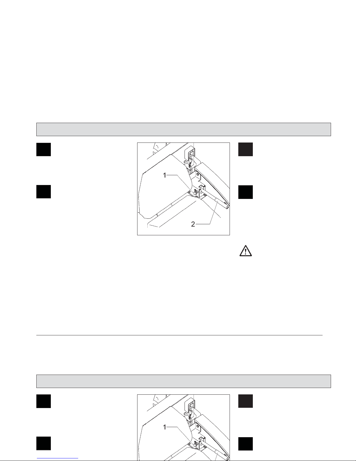
7.6 Replace Side Brush
The side brush is located at the front
right of the machine (standard version). Use the lever (Fig. 10/9) to lift
and lower the side brush. The side
brush is to be lightly inclined in forward and in outward direction. The
swinging area of the side brush arm is
limited by stop screws. The side brush
is driven by a V-belt. Fitting of a
second side brush for specific appliances is possible.
Proceed as follows for dismounting of
the side brush:
Replace side brush
- Turn engine off and pull key.
- Secure machine by engaging parking brake
- Disconnect battery plug
- Side brush lifted
- Loosen hexagonal nut (Fig. 20/1)
und remove together with washer
- Remove bolt (Fig. 20/2)
- Remove side brush
Proceed in inverse order for mounting
of the side brush.
46
Maintenance/Service
Fig.20
7.6 Replace Side Brush
The side brush is located at the front
right of the machine (standard version). Use the lever (Fig. 10/9) to lift
and lower the side brush. The side
brush is to be lightly inclined in forward and in outward direction. The
swinging area of the side brush arm is
limited by stop screws. The side brush
Proceed in inverse order for mounting
of the side brush.
Maintenance/Service

47
7.7 Dismount Plate Filter
Proceed as follows for dismounting of
the plate filter:
- Open seat hood.
- Open quick-release locks
(Fig. 21/1).
- Remove cover, filter case (Fig. 21/3)
- Remove covering hood, plate filter
- Loosen fillister head screws
(Fig. 21/2) and remove.
- Fold back frame with electro-motor
(Fig. 22/3).
- Hook frame at indicated position
(Fig. 22/4)
- Remove plate filter (Fig. 22/5).
For mounting of plate filter proceed in
inverse order.
Replace plate filter
1 Quick-release locks
2 Filter case cover
3 4 Filter case
Maintenance/Service
Fig.21
7.7 Dismount Plate Filter
Proceed as follows for dismounting of
the plate filter:
- Open seat hood.
- Open quick-release locks
(Fig. 21/1).
- Remove cover, filter case (Fig. 21/3)
- Remove covering hood, plate filter
- Loosen fillister head screws
Maintenance/Service

Plate filter
1 Detent hook
2 Wing screws
3 Frame with electro-motor
4 Opening for detent lever
5 Plate filter
48
Maintenance/Service
Fig.22
Maintenance/Service
49
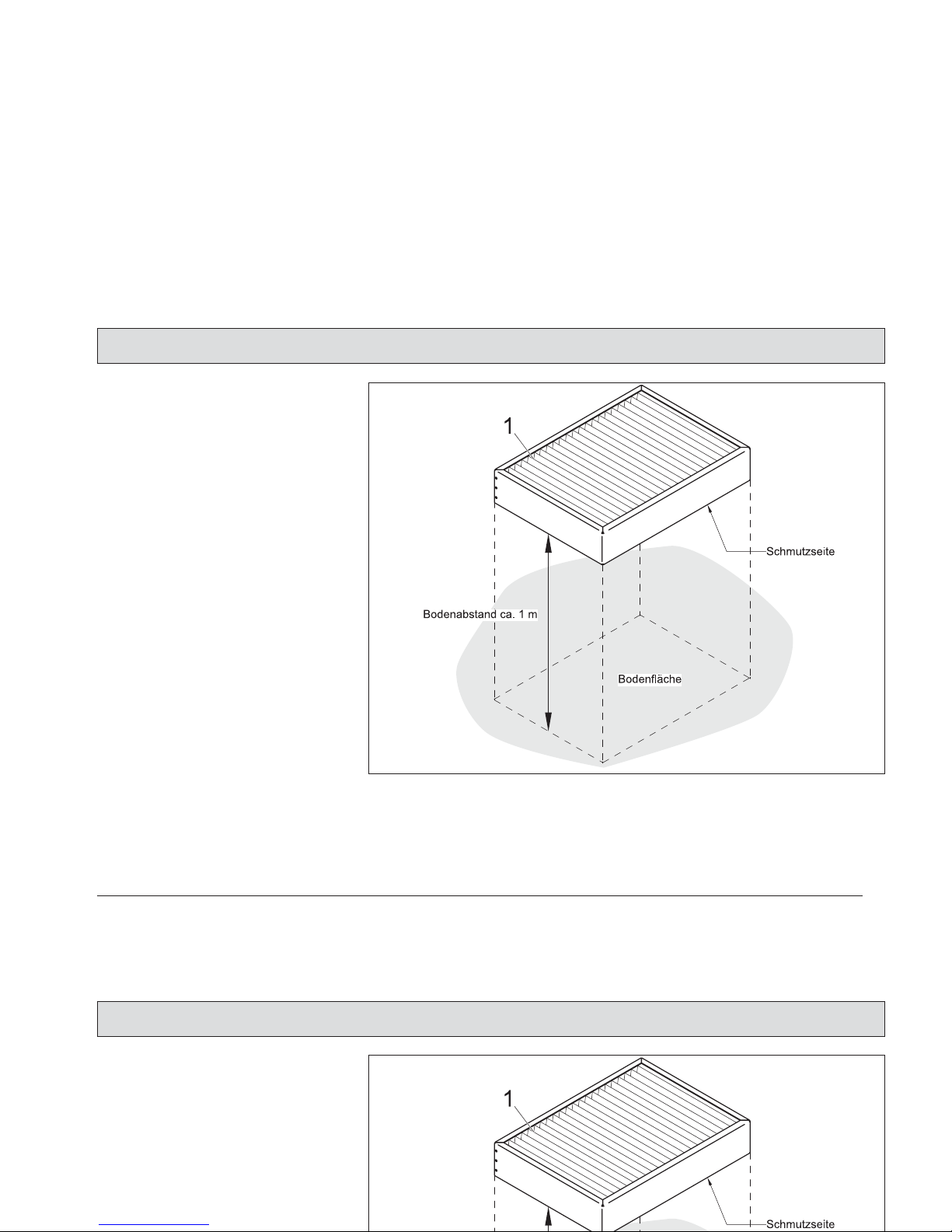
7.8 Basic Cleaning of Plate Filter
Hold the plate filter (Fig. 23/1) in vertical position and let it fall down from a
height of 1 m to the even floor as
represented in Fig. 23.
Basic cleaning of plate filter 1 Plate filter
Maintenance/Service
Fig.23
7.8 Basic Cleaning of Plate Filter
Hold the plate filter (Fig. 23/1) in vertical position and let it fall down from a
height of 1 m to the even floor as
represented in Fig. 23.
Maintenance/Service

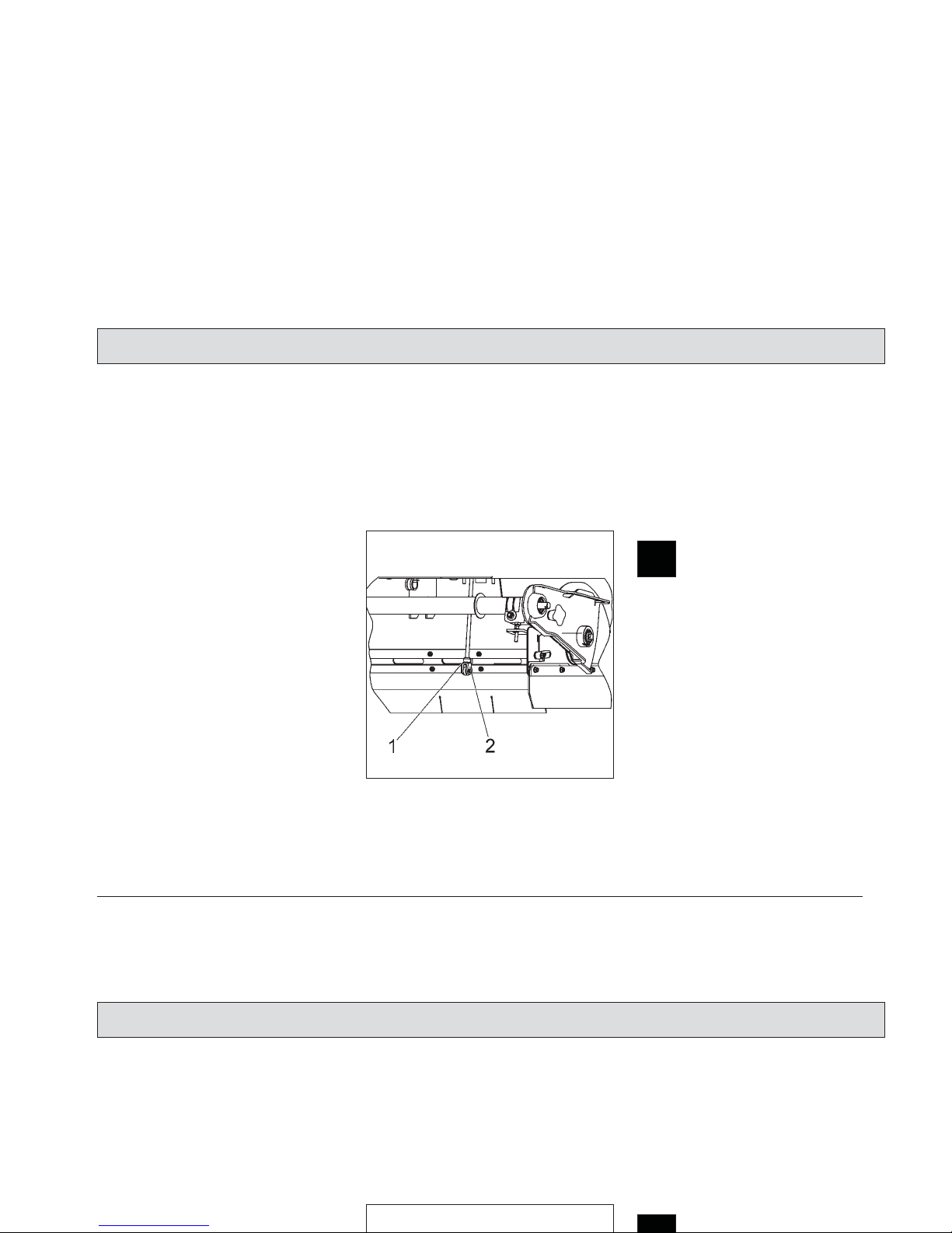
7.9 V-Belt Drive
1 Tensioning roller
2 Suction fan V-belt (20Hz)
3 V-belt pulley
4 V-belt for cylinder broom and side
brush (130 Hz)
5 Side brush V-belt
6 Belt pulley
7 Cylinder broom V-belt
8 Tensioning roller lever
9 Belt pulley
10 Tension spring
11 Hexagonal nut
12 Hexagon socket screw
V-belt drive Apex 47
50
Maintenance/Service
Fig.24
7.9 V-Belt Drive
1 Tensioning roller
2 Suction fan V-belt (20Hz)
3 V-belt pulley
4 V-belt for cylinder broom and side
brush (130 Hz)
5 Side brush V-belt
6 Belt pulley
Maintenance/Service

51
7.9.1 Replace Cylinder Broom
V-Belt
- Turn engine off and pull key.
- Secure machine by engaging parking brake
- Disconnect battery plug
- Detent tensioning spring (Fig. 24/10)
by left hand while taking the V-belt
off the tensioning roller with right
hand
- Remove V-belt (Fig. 24/7)
Proceed in inverse order for mounting
of the side brush.
7.9.2 Replace Side Brush V-Belt
- Turn engine off and pull key.
- Secure machine by engaging parking brake
- Disconnect battery plug
- Remove bottom right cover (turn
locks counter-clockwise by square
spanner).
- Remove cylinder broom V-belt (as
described in paragraph "Replace
Cylinder Broom V-Belt")
- Loosen screws (Fig. 24/13) at the
cover plate and remove
- Remove cover plate
- Push side brush in direction of the
machine to detent V-belt (Fig. 24/5)
- Remove V-belt (Fig. 24/5)
Proceed in inverse order for mounting
of the V-belt.
7.9.3 Replace Suction Fan V-Belt
- Turn engine off and pull key.
- Secure machine by engaging parking brake
- Open seat hood
- Disconnect battery plug
- Open quick-release locks (Fig. 21/1)
- Remove filter case cover (Fig. 21/3)
- Loosen screws at the inside of the
right lateral fairing and remove
- Tilt lateral fairing lightly to the outside, the remove by pulling upwards
- Loosen tensioning roller (Fig. 24/1)
- Loosen hexagonal nuts (Fig. 24/11)
and hexagon socket screw (Fig.
24/12) and detent V-belt (Fig. 24/4)
- Remove V-belt (Fig. 24/4) from Vbelt pulley (Fig. 24/3)
- Remove V-belt (Fig. 24/2)
Proceed in inverse order for mounting
of the V-belt.
Do not exceed tension of V-belt.
Observe the following when
mounting the V-belt:
First adjust tension of V-belt
(Fig. 24/4), the adjust tension of V-Belt (Fig. 24/2).
Maintenance/Service
7.9.1 Replace Cylinder Broom
V-Belt
- Turn engine off and pull key.
- Secure machine by engaging par-
king brake
- Disconnect battery plug
- Detent tensioning spring (Fig. 24/10)
by left hand while taking the V-belt
off the tensioning roller with right
hand
- Remove cover plate
- Push side brush in direction of the
machine to detent V-belt (Fig. 24/5)
- Remove V-belt (Fig. 24/5)
Proceed in inverse order for mounting
of the V-belt.
7.9.3 Replace Suction Fan V-Belt
- Turn engine off and pull key.
Proceed in inverse order for mounting
of the V-belt.
Do not exceed tension of V-belt.
Observe the following when
mounting the V-belt:
First adjust tension of V-belt
(Fig. 24/4), the adjust tension of V-Belt (Fig. 24/2).
Maintenance/Service

7.10 Adjust Steering Chain Tension
Check the condition and function of
steering chain every 200 hours of operation.
Proceed to adjustment of tension via a
spring located in the pedal area and
accessible after removal of the cover
plate.
We recommend having this adjustment work done by qualified personnel
only.
Adjust tension of the steering chain such that rotational movement is possible
without jerks.
7.11 Check Hydraulic Fluid and
Refill
7.11.1 Check Hydraulic Fluid
- Turn engine off and pull key
- Secure machine by engaging parking brake
- Open seat hood
- Check hydraulic fluid level at tank
(Fig. 25/1), the level must not fall
below the minimum mark (Fig.
25/2). It should read between minimum (Fig. 25/2) and maximum mark
(Fig. 25/3).
7.11.2 Refill Hydraulic Fluid
- Remove cover (Fig. 24/4) and refill
hydraulic fluid
- Close hydraulic fluid tank with cover
Use DTE 15M hydraulic fluid or a fluid
of similar quality.
52
Maintenance/Service
Fig.25
7.10 Adjust Steering Chain Tension
Check the condition and function of
steering chain every 200 hours of operation.
Proceed to adjustment of tension via a
spring located in the pedal area and
accessible after removal of the cover
plate.
We recommend having this adjust-
7.11 Check Hydraulic Fluid and
Refill
7.11.1 Check Hydraulic Fluid
- Turn engine off and pull key
- Secure machine by engaging parking brake
- Open seat hood
- Check hydraulic fluid level at tank
(Fig. 25/1), the level must not fall
below the minimum mark (Fig.
25/2). It should read between minimum (Fig. 25/2) and maximum mark
Maintenance/Service

53
7.12 Electric System
7.12.1 Fuses/Relays
1 F2 Pre-fuse (20A)
2 F3 Travel drive assembly control
(10A)
3 F4 Control panel indicators (5A)
4 F5 Horn (5A)
5 F6 Control, main motor and LDS
(5A)
6 F7 LDS measurement (5A)
7 F8 Lighting (7.5A)
8 F9 Lifted-up disposal control
(6502.60) (7.5A)
9 F10 Vacuum cleaner option (30A)
10 F11 Shaking motor (30A)
11 F14 Flashlight option (5A)
12 K4 Time relay, filter monitoring
13 K5 Impulse relay, shaking
14 F12 Main motor (63A)
15 F1 Travel drive assembly (63A)
16 K1 Relay, multimode
17 K12 Relay
18 K3 Relay
19 K2 Relay, motor suction fan/
sweeper
Fuses/relays
Maintenance/Service
Fig.26
7.12 Electric System
7.12.1 Fuses/Relays
1 F2 Pre-fuse (20A)
2 F3 Travel drive assembly control
(10A)
3 F4 Control panel indicators (5A)
4 F5 Horn (5A)
5 F6 Control, main motor and LDS
Maintenance/Service
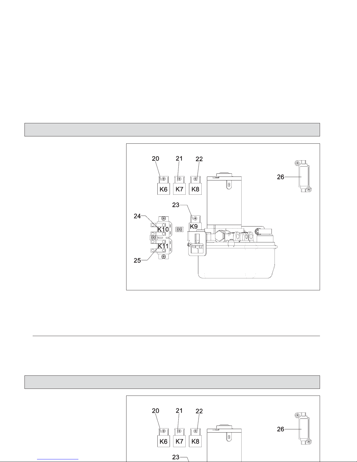
7.12.2 Lifted-Up Disposal
Fuses/Relays
20 K6 Lifted-up disposal
21 K7 Lifted-up disposal
22 K8 Lifted-up disposal
23 K9 Lifted-up disposal
24 K10 Relay, lift dirt hopper
25 K11 Relay, lower dirt
hopper
26 F 13 Hydraulic unit (30A)
Lifted-up disposal fuses/relays
54
Maintenance/Service
Fig.27
7.12.2 Lifted-Up Disposal
Fuses/Relays
20 K6 Lifted-up disposal
21 K7 Lifted-up disposal
22 K8 Lifted-up disposal
23 K9 Lifted-up disposal
24 K10 Relay, lift dirt hopper
25 K11 Relay, lower dirt
Maintenance/Service

Daily
after first
every 100 every 200
Check batter acid level and top with distilled water if required
(with fully charged battery only)
X
Check acid density of battery X
Clean battery poles and greas e X
Check cables for damages and screwed connec tions for tight fit X
Check function of seat c ontact switch X
Visual chec k of front tires X
Check cylinder broom for wearing or foreign particles (e.g. wire,
straps) and replace broom if required
X
Check sweeping track and adjust if required X
Check sealing strips at the broom compartment, adjust if
required or replace defective sealing strips
X
Check sealing strips at dirt hopper, replace defective sealing
strips
X
Check side brush adjustment and brush bristles for wearing,
adjust if required or replace side brush
X
Check V-belt for wearing and correct tension and read
j
ust if required
5 X
7.13 Maintenance Schedule
hours of operation
55
Maintenance/Service
Daily
after first
every 100 every 200
Check batter acid level and top with distilled water if required
(with fully charged battery only)
X
Check acid density of battery X
Clean battery poles and greas e X
Check cables for damages and screwed connec tions for tight fit X
Check function of seat c ontact switch X
7.13 Maintenance Schedule
hours of operation
Maintenance/Service

Daily
after first
every 100 every 200
Visual chec k of V-belts X
Check service/parking brake and re-adjust if required X
Check filter system for tightness (visual check) X
Dismount plate filter and clean if required X
Clean travel drive assembly, brush drive, shaking motor X
Check tread of wheels X
Check function of electro-motor, carbon brushes for smooth
operation and wearing; clean motor from carbon dust and replace
carbon brushes if required
500 X
Check carbon brushes of travel drive assembly (to be executed
by qualified personnel only)
500 X
Check hydraulic hos es and replace if required
Check hydraulic fluid level for lifted-up disposal and refill if
required
X
Check tensioning moment of fixing screws for lifted-up disposal
facility and re-tighten if required (49 Nm)
5 X
Check tension of steering chain and re-adjust tension if required X
7.13 MaintenanceSchedule
hours of operation
56
Maintenance/Service
Daily
after first
every 100 every 200
Visual chec k of V-belts X
Check service/parking brake and re-adjust if required X
Check filter system for tightness (visual check) X
Dismount plate filter and clean if required X
Clean travel drive assembly, brush drive, shaking motor X
7.13 MaintenanceSchedule
hours of operation
Maintenance/Service

57
Maintenance Document
100 operating hours
Maintenance
Workshop stamp
carried out on __________
at __________ operating hours
200 operating hours
Maintenance
Workshop stamp
carried out on __________
at __________ operating hours
300 operating hours
Maintenance
Workshop stamp
carried out on __________
at __________ operating hours
400 operating hours
Maintenance
Workshop stamp
carried out on __________
at __________ operating hours
500 operating hours
Maintenance
Workshop stamp
carried out on __________
at __________ operating hours
600 operating hours
Maintenance
Workshop stamp
carried out on __________
at __________ operating hours
700 operating hours
Maintenance
Workshop stamp
carried out on __________
at __________ operating hours
800 operating hours
Maintenance
Workshop stamp
carried out on __________
at __________ operating hours
900 operating hours
Maintenance
Workshop stamp
carried out on __________
at __________ operating hours
1000 operating hours
Maintenance
Workshop stamp
carried out on __________
at __________ operating hours
1100 operating hours
Maintenance
Workshop stamp
carried out on __________
at __________ operating hours
1200 operating hours
Maintenance
Workshop stamp
carried out on __________
at __________ operating hours
Maintenance Document
100 operating hours
Maintenance
Workshop stamp
carried out on __________
at __________ operating hours
200 operating hours
Maintenance
Workshop stamp
carried out on __________
at __________ operating hours
300 operating hours
Maintenance
Workshop stamp
carried out on __________
at __________ operating hours
400 operating hours
Maintenance
Workshop stamp
carried out on __________
at __________ operating hours
500 operating hours
600 operating hours
700 operating hours
800 operating hours

PowerBoss Made Simple Commercial Limited Warranty
PowerBoss, Inc. warrants to the original purchaser/user that this product is free from defects in workmanship and materials under
normal use. PowerBoss will, at its option, repair or replace without charge, parts that fail under normal use and service when operated and
maintained in accordance with the applicable operation and instruction manuals.
All warranty claims must be submitted through and approved by factory authorized repair stations.
This warranty does not apply to normal wear, or to items whose life is dependent on their use and care, such as belts, cords,switches, hoses,
rubber parts, electrical motor components or adjustments. Parts not manufactured by are covered by and subject to the warranties and/or
guarantees of their manufacturers. Please contact PowerBoss for procedures in warranty claims against these manufacturers.
Special warning to purchaser -- Use of replacement filters and/or prefilters not manufactured by PowerBoss or its designated licensees, will void
all warranties expressed or implied.
A potential health hazard exists without original equipment replacement.
All warranted items become the sole property of PowerBoss or its original manufacturer, whichever the case may be. PowerBoss
disclaims any implied warranty, including the warranty of merchantability and the warranty of fitness for a particular purpose.
PowerBoss assumes no responsibility for any special, incidental orconsequential damages.
This limited warranty is applicable only in the U.S.A. and Canada, and is extended only to the original user/purchaser of this product. Customers
outside the U.S.A. and Canada should contact their local distributor for export warranty policies. PowerBoss is not responsible for costs or repairs
performed by persons other than those specifically authorized by PowerBoss. This warranty does not apply to damage from transportation,
alterations by unauthorized persons, misuse or abuse of the equipment, use of non-compatible chemicals, or damage to property, or loss of
income due to malfunctions of the product.
Minuteman Made Simple Commercial Limited Warranty
Minuteman, Inc. warrants to the original purchaser/user that this product is free from defects in workmanship and materials under
normal use. Minuteman will, at its option, repair or replace without charge, parts that fail under normal use and service when operated and
maintained in accordance with the applicable operation and instruction manuals.
All warranty claims must be submitted through and approved by factory authorized repair stations.
This warranty does not apply to normal wear, or to items whose life is dependent on their use and care, such as belts, cords,switches, hoses,
rubber parts, electrical motor components or adjustments. Parts not manufactured by are covered by and subject to the warranties and/or
guarantees of their manufacturers. Please contact Minuteman for procedures in warranty claims against these manufacturers.
Special warning to purchaser -- Use of replacement filters and/or prefilters not manufactured by Minuteman or its designated licensees, will void
all warranties expressed or implied.
A potential health hazard exists without original equipment replacement.
All warranted items become the sole property of Minuteman or its original manufacturer, whichever the case may be. Minuteman
disclaims any implied warranty, including the warranty of merchantability and the warranty of fitness for a particular purpose.

If a difficulty develops with this machine, you should contact the dealer from whom it was purchased.
This warranty gives you specific legal rights, and you may have other rights which vary from state to state. Some states do not allow the exclusion
or limitation of special, incidental or consequential damages, or limitations on how long an implied warranty lasts, so the above exclusions and
limitations may not apply to you.
Cord Electric Group Three years parts, two years labor, ninety days travel (Not to exceed two hours)
Exceptions Port-A-Scrub, one year parts, six months labor
MPV 13, one year parts
MPV 14 and 18, two years parts, one year labor
Rapid Air blower, one year parts, one year labor
Pneumatic Vacuums, three years parts, one year labor
EX 12 and EX 12H, one year parts, one year labor
Battery Operated Group Three years parts, two years labor, ninety days travel
(Not to exceed two hours)
Exceptions Sweepers, one year parts, one year labor, ninety days travel
(Not to exceed two hours)
Replacement parts Ninety days
Batteries 0-3 months replacement, 4-12 months pro-rate
Polypropyl. Plastic Tanks Ten years, no additional labor
If a difficulty develops with this machine, you should contact the dealer from whom it was purchased.
This warranty gives you specific legal rights, and you may have other rights which vary from state to state. Some states do not allow the exclusion
or limitation of special, incidental or consequential damages, or limitations on how long an implied warranty lasts, so the above exclusions and
limitations may not apply to you.
Cord Electric Group Three years parts, two years labor, ninety days travel (Not to exceed two hours)
Exceptions Port-A-Scrub, one year parts, six months labor
MPV 13, one year parts
MPV 14 and 18, two years parts, one year labor
Rapid Air blower, one year parts, one year labor
Pneumatic Vacuums, three years parts, one year labor
EX 12 and EX 12H, one year parts, one year labor
Battery Operated Group Three years parts, two years labor, ninety days travel
(Not to exceed two hours)

Excellence Meets Clean
PowerBoss Inc. · 175 Anderson Sreet ·Aberdeen, II. NC 28315 ·U.S.A
.
Telephone: (910) 944-2105· Fax (910) 944-740
88-10-2785/12-200 7
Excellence Meets Clean
 Loading...