

Swarm-enabled Solar Battery System
Installation and Operating instructions
PBX-200 PB (230 V, 200 W, 1.2 kWh AGM Battery)
PBX-200 Li (230 V, 200 W, 1.2 kWh Li-ion Battery)
EN
2017-03-13

Installation and Operating Instructions PBX-200 PB / Li page 2
Table of Contents
1! GENERAL(SAFETY(INSTRUCTIONS(...................................................................................................................(3!
2! SCOPE(OF(DELIVERY(......................................................................................................................................(4!
3! INTENDED(USE(..............................................................................................................................................(5!
4! MARKINGS(....................................................................................................................................................(6!
4.1! SYMBOLS!FOR!WARNINGS!AND!NOTES!...................................................................................................................!6!
4.2! SIGNAL!WORDS!.................................................................................................................................................!6!
5! QUICK(START(GUIDE(......................................................................................................................................(7!
6! OVERVIEW(OF(THE(POWER(BLOX(..................................................................................................................(8!
6.1! LEGEND!OF!COMPONENTS!AND!CONNECTIONS!......................................................................................................!10!
7! INSTALLATION(.............................................................................................................................................(11!
7.1! SAFETY!INSTRUCTIONS!......................................................................................................................................!11!
7.2! CONNECTIONS!AND!MAIN!SWITCH!......................................................................................................................!13!
!"#"$! %&'()*+',-.)/01)""""""""""""""""""""""""""""""""""""""""""""""""""""""""""""""""""""""""""""""""""""""""""""""""""""""""""""""""""""""""""""""""""""""")$0!
!"#"#! 2'34-,)-5((4-,'5()6'&)'(,473&,48)*5-94,*)/$1)"""""""""""""""""""""""""""""""""""""""""""""""""""""""""""""""""""""""""""""""""""""""""")$0!
!"#"0! :*4),.4):;<)-5((4-,53*)/=1)/>1)&(8)$#)?)2@)""""""""""""""""""""""""""""""""""""""""""""""""""""""""""""""""""""""""""""""""""""""""""")$=!
!"#"=! @5((4-,'(7),.4)*5A&3)B58CA4),5),.4)*5A&3)*5-94,)/D1)"""""""""""""""""""""""""""""""""""""""""""""""""""""""""""""""""""""""""""""")$=!
!"#">! @5CEA'(7)5F)G5+43H<A5I)""""""""""""""""""""""""""""""""""""""""""""""""""""""""""""""""""""""""""""""""""""""""""""""""""""""""""""""""""""""""""")$>!
!"#"J! %'('BCB)8'*,&(-4*)"""""""""""""""""""""""""""""""""""""""""""""""""""""""""""""""""""""""""""""""""""""""""""""""""""""""""""""""""""""""""""""""")$!!
!"#"!! K(,43-5((4-,'(7)*4643&A),5+ 4 3*) ,5 )&)LE5+43)+&AAL)"""""""""""""""""""""""""""""""""""""""""""""""""""""""""""""""""""""""""""""""""")$!!
!"#"D! :*'(7),.4)-5((4-,'5(),43B'(&A*)/$JH$M1)"""""""""""""""""""""""""""""""""""""""""""""""""""""""""""""""""""""""""""""""""""""""""""""""""")$D!
7.3! CONNECTION!TYPES!.........................................................................................................................................!21!
7.4! SINGLE!SOLAR!SYSTEM!......................................................................................................................................!21!
7.5! COMBINATION!OF!SOLAR!AND!PUBLIC!ELECTRICITY!.................................................................................................!21!
7.6! USE!AS!BACKUP!SYSTEM!(UPS)!..........................................................................................................................!22!
7.7! COMBINED!SOLAR!/!MAINS!SYSTEM!WITH!CONNECTION!TO!THE!TERMINAL!BLOCK!.......................................................!22!
7.8! POWER-BLOX!INSTALLATION!.............................................................................................................................!23!
!"D"$! K(*,&AA&,'5()5F)&)*'(7A4)G5+43H<A5I)""""""""""""""""""""""""""""""""""""""""""""""""""""""""""""""""""""""""""""""""""""""""""""""""""""""""")#0!
!"D"#! K(*,&AA&,'5()5F)&88','5(&A)G5+43H<A5I),5)&),5+43)53)&)G5+43HN&AA)/B&I'BCB)M)C(',*1)"""""""""""""""""""""""""")#=!
!"D"0! K(*,&AA&,'5()5F)E5+43)*O*,4B*)734&,43),.&()M)G5+43H<A5I)"""""""""""""""""""""""""""""""""""""""""""""""""""""""""""""""""""""")#=!
8! INITIAL(START-UP(........................................................................................................................................(25!
9! LED(DISPLAY(................................................................................................................................................(26!
9.1! INDICATES!THE!BATTERY!STATUS!.........................................................................................................................!26!
9.2! DISPLAY!ON!SYNCHRONIZATION!..........................................................................................................................!26!
9.3! DISPLAY!OF!ERRORS!.........................................................................................................................................!26!
10! TROUBLESHOOTING(..................................................................................................................................(27!
11! MAINTENANCE(............................................................................................................................................(28!
12! DISPOSAL(................................................................................................................................ ....................(29!
13! TECHNICAL(DATA(........................................................................................................................................(30!
14! DISCLAIMER(OF(LIABILITY(............................................................................................................................(32!
15! WARRANTY(AND(GUARANTEE(PROVISIONS(................................................................................................(33!
16! HOW(TO(CONTACT(WITH(.............................................................................................................................(37!
17! NOTES(.........................................................................................................................................................(38!

Installation and Operating Instructions PBX-200 PB / Li page 3
1 General Safety Instructions
§ This document is an integral part of the product. It is provided digitally and on request in
printed form.
§ Only qualified personnel are allowed to carry out the measures described in this manual.
§ Do not install or use the device until you have read and understood this document.
§ Always carry out the measures described in this document in the order indicated.
§ Save this document during the life of the device. Pass the document to the following owners
and users.
§ Improper operation can reduce the yield of the solar system or damage the system
components.
§ The device must not be connected with a damaged housing.
§ Disconnect the equipment immediately and disconnect from the solar module and the mains
/ generator if any of the following components are damaged:
— Device (no function, visible damage, smoke development, penetrated liquid etc.),
— connected lines,
— Solar module.
§ Do not switch on the system again before
— the device has been repaired by the dealer or manufacturer,
— damaged cables or solar modules have been repaired by a specialist.
§ Wash the battery immediately on skin or clothing with soapy water and rinse with plenty of
water. In case of injuries consult a doctor immediately.
§ Rinse immediately with plenty of water and seek medical advice.
§ Never cover the appliance.
§ Do not open the housing: Risk of death! Warranty claims forfeited!
§ Never affix the signs and markings affixed to the works, remove them or make them
unrecognizable.
§ If you are connecting an external device, which is not described in this document, please
follow the instructions of the manufacturer! Incorrectly connected devices can damage the
solar system.
§ This appliance is not intended for
— Children,
— People with physical, sensory or mental impairments,
— Persons who do not have sufficient experience and knowledge. Unless they have
been instructed and initially supervised by a person responsible for their safety.

Installation and Operating Instructions PBX-200 PB / Li page 4
2 Scope of delivery
§ 200 PBX or PBX 200-LI
§ Power cord
§ Quick Start Guide
§ Installation and operating instructions (online)
Optional accessories:
§ Solar cables with MC-4-port
§ WP 200 or 250 WP solar module
§ Print version installation and operating instructions

Installation and Operating Instructions PBX-200 PB / Li page 5
3 Intended use
The solar battery system, hereafter referred to as the power-Blox or System referred to, may be
used only in photovoltaic systems.
Furthermore,
§ Only solar modules can be connected to the solar module connector.
§ The connected loads must be suitable for the corresponding output voltage (230 V
alternating voltage, or 12 V / 5 V DC voltage).
§ The connected consumers must not exceed the maximum power of the system (for a
Power-Blox: 200 W, short-term 370 W).
§ The source connected to the GRID / GEN input must match the input voltage range of the
solar system and provide enough power.
Installation and Operating Instructions PBX-200 PB / Li page 6
4 Markings
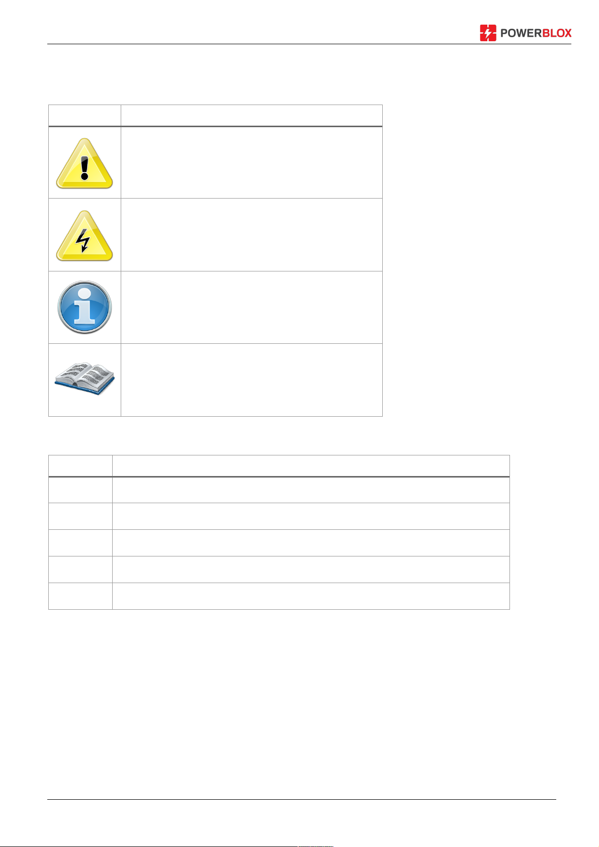
4.1 Symbols for warnings and notes
Symbol
Description
General hazard warning
Danger with electricity
Important note
Read the instructions before using the product
4.2 Signal words
Symbol
Description
Danger
immediate risk of death or serious bodily harm
Warning
possible risk of death or serious personal injury
Caution
Possible risk of minor or moderate bodily injury
Attention
Possible property damage
Note
Note on the operation of the controller or on how to use the instructions
Installation and Operating Instructions PBX-200 PB / Li page 7
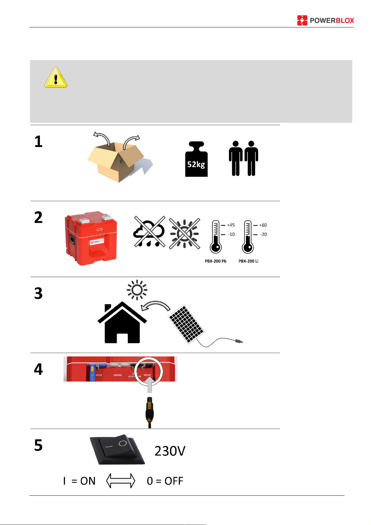
5 Quick Start Guide
DANGER!
Danger to life due to electrocution. Observe the safety instructions in section 9.1
Installation and Operating Instructions PBX-200 PB / Li page 8
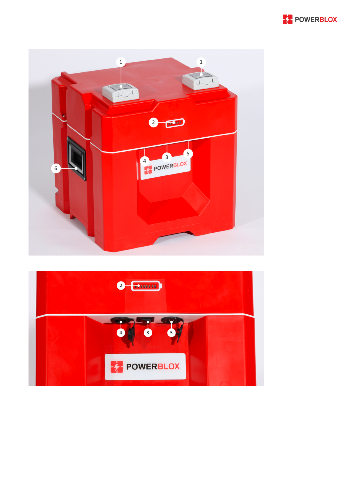
6 Overview of the Power Blox
Figure 1: Power-Blox front page
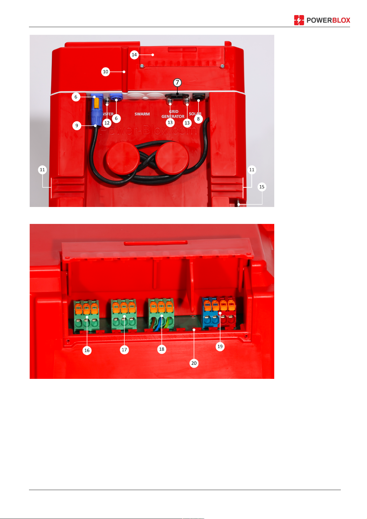
Figure 2: Front connectors and power switch
Installation and Operating Instructions PBX-200 PB / Li page 9
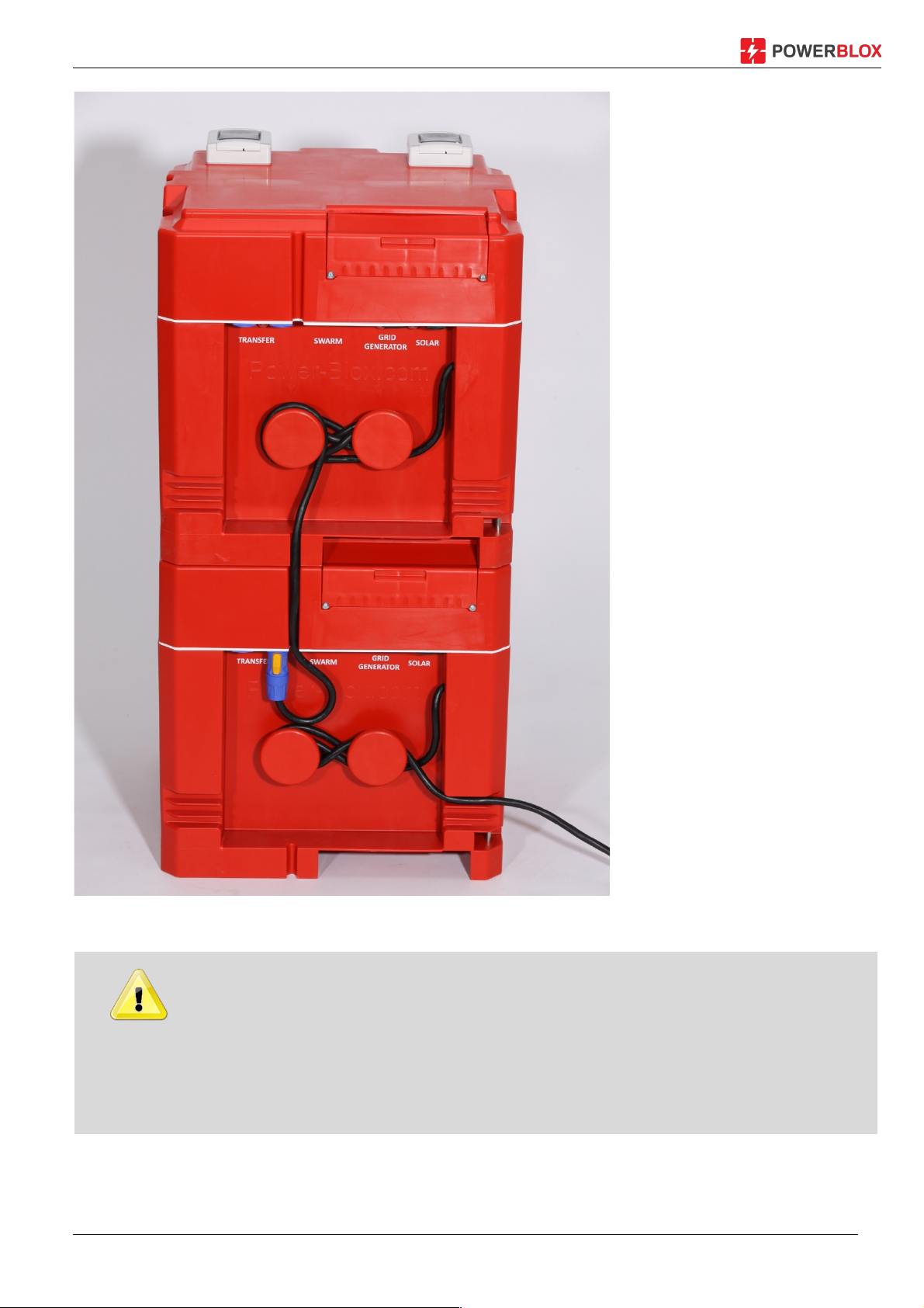
Figure 3: Power-Blox back
Figure 4: Terminal connections behind cover installation

Installation and Operating Instructions PBX-200 PB / Li page 10
6.1 Legend of components and connections
1 AC power socket, 230 V
2 LED display
3 Main switch
4 Cigarette lighter socket 12 V DC, 3 A
5 2 x USB ports 5V, 2.1 A
6 Sockets for transfer cable
7 Cold devices power / generator (input) Jack
8 Solar connector for optional solar cable (input)
9 Transfer cable for connecting power-Blox
10 Vertical cable management channel
11 Horizontal cable ducts
12 Resettable circuit breaker (10 A) for transfer socket
13 Resettable circuit breaker (10 A) for mains / generator input
14 Installation flap for terminal connections
15 Anti-theft locking pins
16 Terminal block transfer connection
17 Not used
18 Terminal block for power / generator input
19 Solar connection terminal block
20 Strain relief bar

Installation and Operating Instructions PBX-200 PB / Li page 11
7 Installation
Only the installation of the power Blox is described below. When installing external
components (solar module, load, cable), observe the instructions of the respective
manufacturer.
Topics
1. Safety Instructions
2. Connections and Operation
3. Setting up the Power-Blox
4. Make electrical connections
7.1 Safety Instructions
DANGER!
Danger to life through electric shock! Observe the following safety instructions when
performing the steps described in the Installation section.
General
- Only qualified personnel are allowed to perform the measures described in the
"Installation" section.
- Power-Blox housing does not open.
The installation flap (14) must be closed and screwed during operation. Before working
with the Power-Blox, always carry out the following measures:
1. Switch off all consumers.
2. If present, open the DC load disconnector (solar module) and secure against
restarting.
3. Open external fuses in front of the generator / mains and transfer terminals and
secure against restarting.
Cabling
- The module cables carry voltage when the solar module is illuminated.
- If the terminals of the mains/generator input (18) are used, the pre-installed cables
must be removed from the terminal block and individually isolated.
- Isolate the open cable ends with an insulating tape or a luster clamp.
- Connect the cables from the solar module and the consumers to the Power-Blox in
the order described.
- Secure the connected cables with a strain relief (20).
- Connect only 1 line to each connection terminal.

Installation and Operating Instructions PBX-200 PB / Li page 12
- Cable: Refer to the Specifications section for details.
- Lay cables so that
— cannot accidentally disconnect connections,
— People cannot step on or stumble over it,
— Fire protection devices.
- Observe all applicable installation regulations and standards, national laws, as well
as the values of the regional power utility.
External circuit breakers
If the terminal blocks (16) - (18) are used for cabling, external circuit breakers as
specified in the section Technical data must be used.
WARNING: Model PBX 200 with lead batteries
Risk of injury from acid.
The Power-Blox contains two AGM lead batteries with 12 V and 50 Ah each.
- Do not expose the battery to open fire or sparks.
- Thoroughly ventilate the installation location of the Power-Blox. Flammable gases
can escape from the battery.
- Store Power-Blox dry.
- Do not expose the Power-Blox to temperatures above 60° C, for example, in closed
cars parked in the sun.
WARNING: Model PBX 200-LI with Li-Ion Batteries
Risk of fire.
The Power-Blox contains two Li-Ion batteries with 12 V and 50 Ah each.
- Do not expose the battery to open fire or sparks.
- Do not expose batteries to temperatures above 60 degrees or below -20 degrees
- Store battery dry
CAUTION!
Danger of damage to the Power-Blox due to overvoltage and overload:
- Observe the technical data, in particular the connection values. See type plate of the
solar module and chapter 13.
- When selecting the solar module, note that its open circuit voltage is higher than
indicated on the rating plate at temperatures below 25° C.
- Only connect one solar module per Power-Blox. Exception: Modules less than 100
Wp whose common open-circuit voltage (series circuit) is not greater than 45 V.
- The maximum open-circuit voltage of the solar module must not exceed 45 V. In
particular thin-film solar modules often have higher open-circuit voltages and are
therefore not suitable for Power-Blox.
- No solar modules with a common power of > 270 Wp.

Installation and Operating Instructions PBX-200 PB / Li page 13
7.2 Connections and main switch
The operation of the Power-Blox is very simple:
7.2.1 Main switch (3)
Power-Blox is controlled in normal use by a main control element: the main switch:
ON ß à OFF
The main switch is switched on by tilting to the left (position I). Tilt to the right (position O) turns
off the Power-Blox.
The Power-Blox starts into a boot and measuring cycle after switching on, so it does not deliver
power directly to the integrated sockets (1). Wait approximately one minute for the Power-Blox
to complete all tests and be ready for operation.
7.2.2 Direct connection via integrated sockets (1)
Figure 5: Use of the integrated sockets.
The two integrated AC power sockets deliver directly high-quality 230 V AC, similar to that at
your household socket. You can directly connect commercially available devices. Make sure you
do not exceed the maximum power of the Power-Blox.

Installation and Operating Instructions PBX-200 PB / Li page 14
7.2.3 Use the USB connectors (4) (5) and 12 V DC
Figure 6: The DC connectors on the front of the Power-Blox
If you want to use the Power-Blox DC power units, you have the possibility to connect a 12 V
device to the maximum of 3 A (car connection) and two USB devices up to 2.1 A at the front.
7.2.4 Connecting the solar module to the solar socket (8)
As an option, Power-Blox offers a solar cable with two standard MC4 connectors on the primary
side and a special solar plug on the secondary side. You can plug it directly into the Power-Blox.
Figure 7: Connect the solar module via solar cable
To connect the solar plug, turn it slightly to the left until it is completely inserted into the socket
and then turn it back until it snaps.
To release the solar plug, pull the yellow lock lever and then turn the plug to the left until it can
be pulled out.

Installation and Operating Instructions PBX-200 PB / Li page 15
For the connection of the solar module, it is not absolutely necessary to obtain a special
solar cable. The module can also be connected directly to the terminal block (19)
hidden behind the installation flap (14). Read more in the chapter 7.7.
7.2.5 Coupling of Power-Blox
By linking individual Power-Blox devices to a whole system, you can achieve several effects:
§ The performance of the entire system is increased
§ The memory of the combined system is increased
§ The daily energy yield is increased
The individual power elements can simply be added with such a coupling:
1 Power-Blox = 200 W Power, 1.2 kWh storage, 200 WP solar power
2 Power-Blox (coupled) = 400 W of Power, 2.4 kWh storage, 400 WP solar power
The individual Power-Blox is coupled by using the integrated transfer cable (9). This
approximately 1.7 m long cable makes it possible to connect vertically (stacked Power-Blox or
Power-Tower) or horizontally placed Power-Blox or towers (Power-Wall).
Installation and Operating Instructions PBX-200 PB / Li page 16
The figure below shows how
two Power-Blox can be
coupled together.
Before the two units are
coupled, switch off both units.
The transfer cable (9) of the
upper unit is now passed
through the cable guide
channel (10) and connected to
one of the two transfer
sockets (6) of the lower unit. It
does not matter which of the
two transfer sockets (6) is
used.
After switching on the two
Power-Blox both Power-Blox
synchronize and form a
"swarm net".
Up to three Power-Blox can
be connected to a tower and
several towers can be coupled
to each other.
Figure 8: Two coupled Power-Blox as a power tower
DANGER!
Do not form any towers that are higher than three units. Each Power-Blox weighs 52kg
and a tall tower could fall over and hurt you. Higher towers are unstable and can easily
tilt if they are not properly fixed or on a bad ground.
The resulting tower is provided at the sockets outlet (1) the power of all Power-Blox in the tower.
If you want to create larger mini-grids, go to chapter 7.8.3.

Installation and Operating Instructions PBX-200 PB / Li page 17
7.2.6 Minimum distances
Figure 9: Minimum distance between two Power-Blox (towers) and an adjacent wall
If you place several Power-Blox or Power-Towers next to each other, be sure to keep a
minimum distance between the units of at least 10cm. To an adjacent wall, the units should be
at least 20cm apart. This enables correct ventilation as well as safe handling.
If you have several tall towers next to each other, you can also make more sense to reach the
transfer cables and the integrated circuit breakers even after commissioning.
7.2.7 Interconnecting several towers to a "power wall"
Figure 10: Connect multiple power Blox towers
The interconnection of several towers takes place analogously to the coupling process
described in the previous chapter to a Power-Blox tower. In this case, the transfer cable (9) of
the lowest power-blox is connected to the transfer bush (6) of the neighboring tower.

Installation and Operating Instructions PBX-200 PB / Li page 18
Thus, the system delivers the performance of the entire system at one of the top sockets of a
tower. In our example, with 9 Power-Blox, this results in 9 x 200 W = 1.8 kW power, which can
be tapped at the socket. Please note that some types of sockets are designed for a lower
maximum power depending on the country specification.
7.2.8 Using the connection terminals (16-19)
DANGER!
Installations in which the connection terminals (16-19) are used may only be carried out
by qualified and trained specialists. In case of improper handling, life risks due to
electric shock as well as the risk of fire and destruction of individual components.
All connections of the Power-Blox are also available as terminals as an alternative to the plug
sockets. A connection to the terminals can be advantageous in the following situations:
§ Connection of a solar module with its own cable without special solar plug on the
secondary side (Power-Blox)
§ Connection of two solar modules in parallel connection (observe max. Power, see
technical data in chapter 13)
§ Connect two Power-Blox or towers over a larger distance, for example between two
buildings
§ Connection of a generator with a self-made cable
§ Connection to the public electricity network with a self-made cable
§ Connection to a fuse box, for example to supply a building installation
§ Connection to a fuse box for the coupling of several power-walls to a large plant
Before installation on Power-Blox terminals:
§ Turn Power-Blox off
§ Disconnect the power cable (7) from the Power-Blox
§ Disconnect the transfer cable from (9) and the (6) Power-Blox
§ Disconnect the solar cable (8) from the Power-Blox
§ Checking the LED display: It may not light
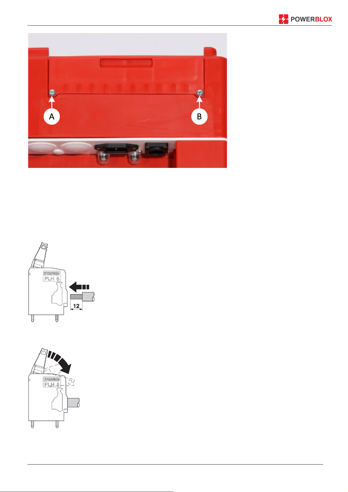
After these steps, the two locking screws (A) and (B) of the installation flap can be loosened with
a Phillips screwdriver:
Installation and Operating Instructions PBX-200 PB / Li page 19
Figure 11: Fuse screws of the installation flap
Now the terminal blocks for the connection of external cables are visible. In order to keep the
installation flap locked during the installation process, it can be pressed vertically vertically
downwards in the fully open position (stop point).
Prepare the cables according to the following drawing and push them as far as they will go into
the corresponding opening of the terminal:
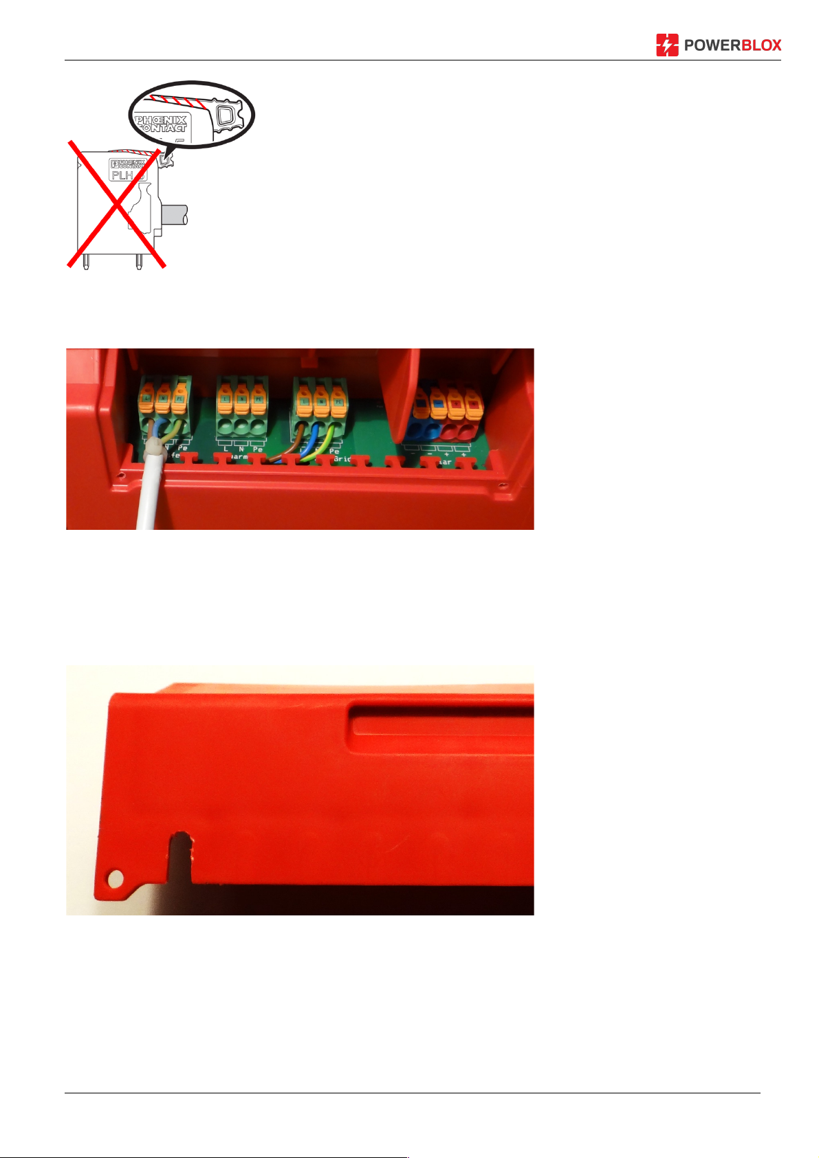
Now close the terminals:
When closing, ensure that the clamp is fully closed and the bracket does not protrude:
Installation and Operating Instructions PBX-200 PB / Li page 20
After connection to the clamping block, the cable can be secured to the strain relief web (20) by
means of a cable tie.
Figure 12: Securing the cable with a cable tie on the strain relief bar
To feed the cable from the Power-Blox, the Power-Blox break-out tabs are provided in the
installation cover. In this case, break out a tab at a suitable location, for example with a side
cutter or a Japanese knife:
Figure 13: Tighten the tab to the cable entry
After completion of all installation work on the terminal blocks, close the installation flap and
secure it with the retaining screws (A) and (B).
Installation and Operating Instructions PBX-200 PB / Li page 21
7.3 Connection types
Power-Blox is very modular and can therefore be interconnected in a variety of ways. The wiring
types listed in this manual are only examples. Before installation, ensure that the type of wiring
you choose is permitted according to your local state regulations and meets all safety criteria.
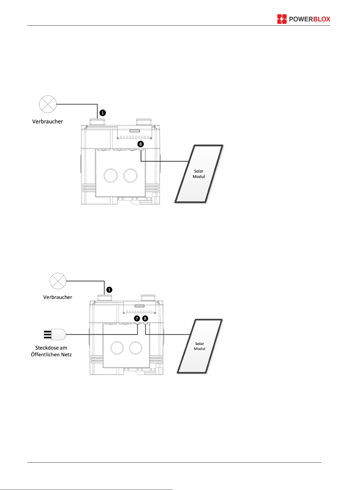
7.4 Single solar system
Figure 14: Single solar system with solar panel
If you want to use a Power-Blox as a single independent system and connect loads directly to
the integrated sockets (1), connect the solar module directly to the solar sleeve (8) and the two
MC4 plugs with the solar module via the optionally available standard cable.
7.5 Combination of solar and public electricity
Figure 15: Power-Blox with connected solar module and network support
If you have a connection to the public power supply, we recommend you connect the PowerBlox to the grid / mains input (7) using the supplied mains cable. The solar system will always
use the energy of the solar system as a priority, but will use the public power to support the
solar system. This extends the life of the built-in batteries.
Installation and Operating Instructions PBX-200 PB / Li page 22
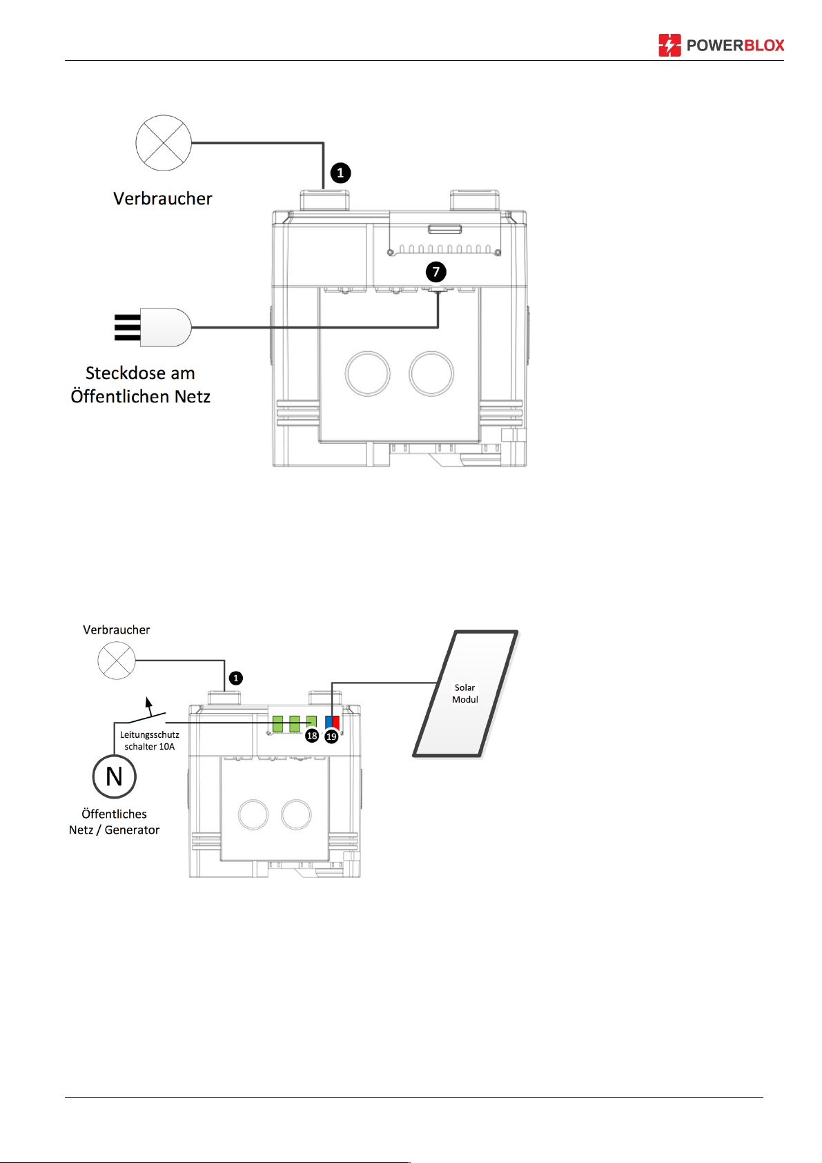
7.6 Use as backup system (UPS)
Figure 16: Interconnection of the Power-Blox as a pure backup unit
If you are using the Power-Blox as an interruption-free power supply, simply connect it to the
power outlet using the supplied power cord and use the integrated sockets (1) to feed your
appliances. In the event of a power failure, the devices are fed by the internal battery.
7.7 Combined solar / mains system with connection to the terminal block
Figure 17: Single solar system wired via terminal blocks
The terminal blocks allow you to build the solar system with standard wiring and wires. In the
schematic diagram shown, the solar module was connected to the terminal block (19) and the
public network to terminal (18).

Installation and Operating Instructions PBX-200 PB / Li page 23
IMPORTANT!
Terminal (19) is connected to the mains input of the Power-Blox as standard, so you will
already find three installed cables on these terminals. To avoid dangerous mains
voltage at the contacts of the mains socket (7), remove the three pre-installed cables
before connecting the mains to terminal (18) and isolate them individually with insulating
tape or luster terminals. Only one of the three cables of the mains socket or an external
cable may be connected to the terminals (18), but not both at the same time.
Make sure that no power cord is plugged in during this work.
7.8 Power-Blox installation
CAUTION!
Danger of damage and degradation of the device. Danger of injury during transport and
installation.
Observe the following safety precautions during installation:
§ The installation area and the surrounding area are stable, horizontal, level, flame-
resistant and not permanently vibrating.
§ To the Power-Blox is on all sides a free space as described in chapter 7.2.6.
§ The Power-Blox is easy to access and the LED display is easy to read.
§ The Power-Blox is not
— outdoor equipment and should not be in a place exposed to rain or splashing
water,
— in a dusty environment.
— in stables with active animal husbandry,
— in direct sunlight.
— At locations in which the maximum temperature can be exceeded or the
minimum temperature can be fallen below.
§ Lifting/moving: The Power-Blox weighs approximately 52 kg (Li-Ion version 27
kg). Make sure that at least two people are installing the unit.
§ Always wear personal protective equipment (protective clothing, gloves, safety
shoes) as there is a risk of injury.
§ When building a tower from several Power-Blox, make sure that the tower
cannot tilt.
§ Do not build any towers higher than three Power-Blox units.
7.8.1 Installation of a single Power-Blox
1. Place of assembly in compliance with the above safety conditions as well as the
necessary distances according to chapter 7.2.6
2. Wipe the surface clean

Installation and Operating Instructions PBX-200 PB / Li page 24
3. Power-Blox set up
4. Mount the solar module using a suitable mount at the destination
5. Lay the solar cable to the Power-Blox and connect it to the solar socket (8) or the
clamping block (19)
6. If necessary, transfer the transfer connector (16) to the building distributor
7.8.2 Installation of additional Power-Blox to a tower or a Power-Wall (maximum 9 units)
1. According to the previous chapter, install the first Power-Blox
2. Put Second Power-Blox on top and make a tower. The sockets must point in the same
direction
3. Put the third Power-Blox on top of the tower and in turn check the socket orientation
4. Cable the tower according to the instructions in chapter 7.2.5
5. Next Power-Blox next to the existing tower place and in turn minimum distances
according to chapter 7.2.6
6. Transfer cable (9) from the first tower to the last Power-Blox and connect it to transfer
socket (6). See also wiring diagram in chapter 7.2.7
7. Now continue with next Power-Blox as described in step 2, until the maximum number of
nine Power-Blox of the Power-Wall is reached
8. If necessary, transfer the transfer connector (16) to the building distributor
7.8.3 Installation of power systems greater than 9 Power-Blox
1. Install several power-walls according to the previous chapter
2. Within the building distributor, the individual power-walls can be routed through a 10 A
(Type B) line circuit breaker and the phases of the individual power-walls can be
combined again behind the line protection switches

Installation and Operating Instructions PBX-200 PB / Li page 25
8 Initial start-up
1. Go to chapter 7.8 for the described steps
2. Check all connections and connections
3. Make sure that all devices attached to the outlet are switched off
4. Turn the main switch (3) to "I"
5. Wait at least 60 seconds for the startup to complete
6. Now the system is ready for operation

Installation and Operating Instructions PBX-200 PB / Li page 26
9 LED display
Figure 18: Display status of the LED display
The LED display has several functions:
§ Indicates the battery status
§ Show the current direction and strength
§ Visualization whether voltage is present at the output
§ Display of various errors
9.1 Indicates the battery status
The LED indicates the current charging status of the battery. Refer to the respective status in
Figure 18. Up to 50% charging status (SoC = State of Charge) the status is displayed with green
LED. When the discharge reaches 40%, the indicator changes to orange and 30% to red. Below
20% the inverter is switched off and the last red LED starts flashing.
Operate the Power-Blox only in the green area of the display. In this charging area the battery is
spared and has the highest life expectancy.
9.2 Display on synchronization
When the Power-Blox synchronizes with its neighbors, it shows an orange running light. This
changes to green as soon as the synchronization is successful.
When synchronized to a mains or generator, the running light can stop for a short time. This ad
behavior is normal. As soon as the Power-Blox has synchronized to the mains, the battery status
is displayed and the battery is charged as required.
9.3 Display of errors
If a fault occurs during operation, the entire display flashes red rapidly one after the other. It then
attempts to switch back to normal operation. If this is not done several times, all LEDs will
remain red.

Installation and Operating Instructions PBX-200 PB / Li page 27
10 Troubleshooting!
If the system does not work normally, proceed as described for the various problems.
No output voltage at the 230 V socket (1)
§ Check whether the main switch (3) is set to "I" (On)
§ Do the LED indicators light up?
o Only one red LED lights up and flashes
à your power Blox is too deeply discharged to deliver power
à Leave the unit charged for one day in the sun or on the mains until at least six
green LEDs light up again
o Yes, several LEDs light up
à Did you wait 60 seconds after switching on the Power-Blox? The unit requires a
certain amount of time until the power supply (1) is available.
à Plug your power supply into the second socket and check that there is no
voltage present. You may have attached too much load. A Power-Blox delivers 200
W. If the load is too high, the output is switched off. Remove the attached device
and wait 60 seconds
à Have the Power-Blox checked by a service technician if all actions do not
improve
o No LED is lit.
à If you have just switched on, wait 60 seconds
à If a LED still lights up after one minute, have the device checked by a technician
I have voltage at output, but not full 230V
§ At most, the load attached is too large
à Remove the load and wait 60 seconds
à and attach a smaller load
The Power-Blox does not charge, the battery indicator shows a falling charge even though
the sun is shining
§ Check whether the cable between Power-Blox and the solar module is correctly
connected and not broken
§ Make sure the solar module
o Is not in a shaded area
o There is no snow on it

Installation and Operating Instructions PBX-200 PB / Li page 28
11 Maintenance
The Power-Blox is practically maintenance-free. Nevertheless, it is recommended to check them
regularly (correct function and display) and clean them as described below.
Do not use sharp cleaning or solvents for cleaning. Clean the Power-Blox with a damp
cloth and some soapy water. Make sure that no liquid enters the inside of the PowerBlox, especially not in the sockets and terminal blocks.
Check regularly the charging status of the Power-Blox. The LED display always shows a green
charge state (>40%) at all times. A lower charging state (orange, red) will not destroy the device,
but will shorten the life of the battery.
In a system with multiple Power-Blox (see chapter 7.2.5) all devices should show the same load
status. If a Power-Blox deviates, this indicates a problem.

Installation and Operating Instructions PBX-200 PB / Li page 29
12 Disposal
Do not dispose of this device through domestic waste! Dispose of the device at the collection
point provided in your country or send the device to the Power-Blox customer service after the
end of its service life.
The packaging of the device consists of recyclable material.

Installation and Operating Instructions PBX-200 PB / Li page 30
13 Technical data
!"#$%&$% '()*+,,-'. '()*+,,-/0
Rated&grid&voltage
Rated&frequency
Phases
Harmonic&distortion
Continuous&power&at&25 °
Power&for&5&sec.&at&25°
Power&for&3&sec.&at&25°
Maximum&load
Cos&ϕ
1%02-3-4$"$%5&6%-0"78&
Input&voltage
Frequency&range
Grid&charger¤t
Charging&characteristics
IUoU
1
Li&BMS
1
Resettable&fuse
9%5":;$%-<6""$<&6%:
Transfer&voltage
Frequency&range
Resettable&fuse
=6>5%-0"78&
Solar&charger&type
Input&voltage&range
PV¤t
Maximum&PV&power
Recommended&PV&power
Charging&characteristics
IUoU1,&temperature&
regulated
Li&BMS1,&temperature&
regulated
(5&&$%?
Included&batteries
2&x&Hoppecke&
sun&power&VR&M&12&V&58
2&x&SmartBattery&
12&V&50&AH
Battery&technology
Lead&acid&/&AGM
3
LiFePO4
4
Internal&battery&voltage
Cycle&stability
2500&cycles& 5000&cycles
Expected&lifetime 3&-&5&Jahre >&10&Jahre
@A-B8&78&
Cigarette&lighter&socket
USB&socket
230&W
230&V
50&Hz
1&Phase
<4%
200&W
370&W
Up&do&short-circuit
0.1&bis&1
230&V&±15%
47&-&64&Hz
5&A
10&A
230&V&±15%
47&-&64&Hz
10&A
MPP
2
30&-&45&V
8&A
250&W
200&W
24V
12&V,&3&A
2&x&5&V,&2&A

Installation and Operating Instructions PBX-200 PB / Li page 31
Connectors
Solar
Transfer+/+stacking
Transfer+cable
Grid+/+generator
Clamps
Swarm-connection
Stacking+possibility
Connecting+towers
Maximum+tower+height
Maximum+stacking+/+transfer+power
Maximum+swarm-grid+size
Certificates
EMC+(Electro+Magnetic+Compatibility)
Safety
Environmental-conditions
Protection+index
Relative+humidity+ in+operation
Operating+temperature+range
-10+to+45°C
5
-20+to+60°C
Ventilation
Warranty 2+years 5+years
1.3m+cable+with+Neutrik+powerCON+plug
Neutrik+powerCON+TRUE1+inlet+/+clamps
Neutrik+powerCON+inlet+/+clamps
Grid+socket+C14,+10A+/+clamps
Tool-less+Phoenix+clamps,+0.2+-+6mm2
Via+attached+cable
Via+attached+cable
3+units
IP20
95%+without+condensation
Passive,+no+active+ventilators
10+Einheiten+/+2.3+kW
Infinite6,+tested+up+to+20+units
IEC/EN55022,+IEC/EN61000
EC/EN62109-1,+IEC62109-2
1
IUoU =Multi-stage charging process for optimal battery charging.
BMS = Battery Management System
2
MPP = Maximum PowerPoint Tracker for up to 30% higher solar yield
3
AGM = Absorbent Glass Mat, electrolyte is bonded in a nonwoven of glass fibers
4
LiFePo4 lithium iron phosphate
5
If the operating temperature is above 30 ° C, the batteries age considerably faster
6
Theoretical value, which must be tested for the new technology only in practice

Installation and Operating Instructions PBX-200 PB / Li page 32
14 Disclaimer of liability
Both the observance of these instructions as well as the conditions and methods for the
installation, operation, use and maintenance of the Power-Blox can not be monitored by the
manufacturer. Incorrect execution of the installation can lead to damage to property and to
subsequent persons.
Therefore, the manufacturer assumes no responsibility and liability for any loss, damage or
expense resulting from faulty installation, faulty installation work, improper operation, incorrect
use and maintenance, or in any way connected with it.
We also assume no responsibility for patent infringement or infringement of other rights of third
parties resulting from the use of the controller.
The manufacturer reserves the right to make changes to the product, the technical data or the
assembly and operating instructions without prior notice.

Installation and Operating Instructions PBX-200 PB / Li page 33
15 Warranty and guarantee provisions
Guarantee conditions for products of Power-Blox AG
On all Power-Blox products, the customer has a 2-year warranty in accordance with statutory
regulations within Switzerland and the European Union.
The acquisition of a Power-Blox product involves a two-year manufacturing warranty of PowerBlox AG. If the Power-Blox products are purchased through a third party (eg supplier or project
developer), the warranty and guarantee provisions shall apply in accordance with the
agreements with the third party. Warranties and complaints must be addressed to these third
parties.
1. Products subject to warranty
The manufacturing guarantee applies to the products of Power-Blox AG (hereinafter referred to
as "Power-Blox") as long as they are demonstrably purchased by Power-Blox or a major, dealer
or specialist installation company authorized by these authorized dealers ("guaranteed
products").
This manufacturing guarantee starts from the date of invoice or receipt and ends 2 years after
the date of the receipt (customer's purchase slip); Or at least 2.5 years after the production date.
The statutory warranty rights are not restricted by the manufacturing guarantee. In order to be
eligible for the guarantee, the customer must present the proof of payment (purchase
document).
If the customer finds a problem, he must first contact his dealer / installer or the Power-Blox AG.
2. Beneficiaries of this manufacturer's guarantee
Power-Blox will only issue this guarantee to the operator, who is proven to have acquired a
product which is entitled to a guarantee, and who operate the product entitled to the warranty
itself ("operator entitled to guarantee") The proof is deemed to have been provided if Power-Blox
is presented with the purchase voucher of the product, which is issued to the authorized
operator. Traders of any kind and degree of trading acquire no rights and claims from this
manufacturing guarantee against Power-Blox.
3. Scope and duration of the warranty
The manufacturing warranty gives guarantee claims against Power-Blox. This warranty is the
exclusive right to eliminate the product deficiency.
A defect in the sense of the manufacturing guarantee is a not insignificant impairment of the
functions of the warranty-entitled product. Warranty claims against the respective seller and
statutory product liability claims shall remain unaffected by the manufacturing guarantee.
The manufacturing guarantee applies to deficiencies which are demonstrable from the date of
purchase (the date of purchase) and the end of the twenty-fourth month of a product with
warranty rights to the guaranteed operator ("guarantee period").

Installation and Operating Instructions PBX-200 PB / Li page 34
Legal warranty claims of any kind can not be derived from this manufacturing guarantee. Any
claims arising from the manufacturing guarantee shall be asserted by the warranty-entitled
operator within two months after the first occurrence of the defect against Power-Blox. Such
guarantee claims are to be registered with their seller (trade chain) or, if necessary, directly with
Power-Blox. At the end of the two months no claims can be claimed from this manufacturing
guarantee.
4. Assertion of the manufacturing guarantee
The settlement of the guarantee is to be carried out as follows.
First of all it is necessary to clarify the extent to which the problem can be caused by the
product.
To do so, contact your salesperson or contact Power-Blox directly.
You send a faulty unit to the seller or directly to power Blox together with a description of the
fault, a copy of the proof of purchase and a description of the mission system.
Power-Blox will analyze the device if warranted, if necessary repair or replace it and return it free
of charge.
If no guarantee claim is given, the customer is informed and receives a cost estimate for repair
or an offer for a replacement device.
For the verification of an intact device without error and in the rejection of a cost estimate,
Power-Blox reserves the right to charge a lump sum.
If no repair or replacement takes place, the customer bears the costs for a possible return of the
defective product. However, Power-Blox also offers a free, proper disposal of the defective
device.
5. Material or processing errors
The manufacturing guarantee as well as the warranty apply only to material, processing and
software errors, as far as these are attributable to lack of professional competence on the part of
Power-Blox.
Power-Blox reserves the right, at its sole discretion, to repair, replace or replace the defective
products. If a software error occurs, a software update can be installed. There is no general
requirement for a software update for a product expansion. For products guaranteed or replaced
by Power-Blox, the warranty is valid until the end of the original warranty period.
Power-Blox generally provides a 6-month warranty for a repair.
6. Rights from the manufacturing guarantee - Unrecognized damages and costs
In the event of a defect of the warranted products during the warranty period - at the option of
Power-Blox - a free repair or replacement by a product which has at least the same or better
specifications. The repair or replacement is carried out exclusively at the Power-Blox plant or at
the authorized service centers of Power-Blox.
Transport to Power-Blox must be carried out in the original or at least equivalent packaging. All
shipping charges shall be borne by the operator with warranty rights. In the Garantiefall, PowerBlox will bear the costs for the return. Outside of the guarantee claim, the shipping costs will be
calculated in the event of a return. Possibly Transport damage must be reported immediately to
the carrier.

Installation and Operating Instructions PBX-200 PB / Li page 35
Any claims arising out of this manufacturing guarantee beyond a free repair or free exchange
shall be excluded, in particular claims for the replacement of deficiencies due to deficiencies,
e.g. Loss of profit, including remuneration for non-performance, installation and removal costs
and the cost of troubleshooting. If no substantial defect is found in the delivered warrantyprotected product, or if no other claim is due to the manufacturing guarantee, Power-Blox may
require the warranty-protected operator to charge a processing fee per delivered product.
This manufacturing guarantee does not entitle the customer to service, to repair or to replace the
product on site.
7. Warranty exclusion
The warranties for products of Power-Blox AG described under item 1 above shall not apply in
the event that the error is due to:
(1) Specifications, design, accessories or components added to the product by the customer or
at the customer's request, or specific instructions from the customer regarding the production of
the product, the coupling (of Power-Blox products) with any Products, or copies of the product
which are not expressly approved by Power-Blox AG;
(2) modifications or adaptations to the product by the customer or other causes attributable to
the customer;
(3) the non-conforming arrangement or assembly, for incorrect or negligent handling, accident,
transport, overload, storage or damage by the customer or third parties;
(4) an unavoidable accident, fire, explosion, construction or new construction of any kind in the
environment in which the product is placed, natural phenomena such as lightning, earthquake,
flood or storm or any cause outside the sphere of influence of the Power-Blox AG;
(5) any cause which can not be foreseen or avoided with the applied technologies used in the
assembly of the product;
(6) when the serial number and / or the type number has been manipulated or rendered
unreadable;
(7) the use of the solar products in a mobile object, for example in ships, caravans or the like.
(8) Do not comply with the recommended maintenance and maintenance instructions on the
product by Power-Blox in the operating instructions.
(9) The housing is damaged, soiled or painted, which makes cleaning or repair impossible.
8. Transferability of manufacturing guarantee
The mentioned manufacturing guarantee applies only to the beneficiaries of the guarantee (see
point 2).
The guarantee given here is not transferable to third parties. The Customer shall not transfer its
resulting rights or obligations in any way without prior written authorization from Power-Blox AG.
In addition, Power-Blox AG will in no event be liable for indirect damage or loss of income.
Subject to any mandatory statutory provisions, Power-Blox AG shall not be liable for damages
other than those for which Power-Blox AG has expressly acknowledged its liability.

Installation and Operating Instructions PBX-200 PB / Li page 36
9. General regulations
Claims of the guarantor of the guarantee-entitled operator from this manufacturing guarantee
shall only be assignable to third parties with the prior written consent of the Power-Blox.
Should a provision of this manufacturing guarantee be or become invalid, the effectiveness of
the remaining provisions of the manufacturing guarantee shall remain unaffected. In the place of
the ineffective or ineffective provision, an effective regulation is automatically agreed as to which
of the invalid or ineffective provision comes as close as possible to their economic content. In
the case of a gap, the above regulation applies accordingly. This manufacturing guarantee is
exclusively subject to Swiss law, excluding the provisions of international private law and the UN
purchase law. The exclusive jurisdiction for all disputes arising from or in connection with this
manufacturing guarantee is Aarau, Switzerland.

Installation and Operating Instructions PBX-200 PB / Li page 37
16 How to contact with
For complaints and faults, please contact your local dealer where you bought the product. This
will help you in all matters.
Dealer: .................................................................................
Street, No: .................................................................................
Zip Code: .................................................................................
.................................................................................
Telephone: .................................................................................
Email: .................................................................................
Website: .................................................................................

Installation and Operating Instructions PBX-200 PB / Li page 38
17 Notes
Type: ..........................................
Serial-No: ..........................................
 Loading...